EP0036610B1 - Method of energizing a fuel-heated heat source - Google Patents
Method of energizing a fuel-heated heat source Download PDFInfo
- Publication number
- EP0036610B1 EP0036610B1 EP81101963A EP81101963A EP0036610B1 EP 0036610 B1 EP0036610 B1 EP 0036610B1 EP 81101963 A EP81101963 A EP 81101963A EP 81101963 A EP81101963 A EP 81101963A EP 0036610 B1 EP0036610 B1 EP 0036610B1
- Authority
- EP
- European Patent Office
- Prior art keywords
- valve
- fuel
- shut
- heat source
- pressure
- Prior art date
- Legal status (The legal status is an assumption and is not a legal conclusion. Google has not performed a legal analysis and makes no representation as to the accuracy of the status listed.)
- Expired
Links
Images

Classifications
-
- F—MECHANICAL ENGINEERING; LIGHTING; HEATING; WEAPONS; BLASTING
- F23—COMBUSTION APPARATUS; COMBUSTION PROCESSES
- F23N—REGULATING OR CONTROLLING COMBUSTION
- F23N1/00—Regulating fuel supply
- F23N1/06—Regulating fuel supply conjointly with draught
- F23N1/067—Regulating fuel supply conjointly with draught using mechanical means
-
- F—MECHANICAL ENGINEERING; LIGHTING; HEATING; WEAPONS; BLASTING
- F23—COMBUSTION APPARATUS; COMBUSTION PROCESSES
- F23N—REGULATING OR CONTROLLING COMBUSTION
- F23N2235/00—Valves, nozzles or pumps
- F23N2235/02—Air or combustion gas valves or dampers
- F23N2235/04—Air or combustion gas valves or dampers in stacks
-
- F—MECHANICAL ENGINEERING; LIGHTING; HEATING; WEAPONS; BLASTING
- F23—COMBUSTION APPARATUS; COMBUSTION PROCESSES
- F23N—REGULATING OR CONTROLLING COMBUSTION
- F23N2235/00—Valves, nozzles or pumps
- F23N2235/12—Fuel valves
- F23N2235/14—Fuel valves electromagnetically operated
-
- F—MECHANICAL ENGINEERING; LIGHTING; HEATING; WEAPONS; BLASTING
- F23—COMBUSTION APPARATUS; COMBUSTION PROCESSES
- F23N—REGULATING OR CONTROLLING COMBUSTION
- F23N2235/00—Valves, nozzles or pumps
- F23N2235/12—Fuel valves
- F23N2235/18—Groups of two or more valves
-
- F—MECHANICAL ENGINEERING; LIGHTING; HEATING; WEAPONS; BLASTING
- F23—COMBUSTION APPARATUS; COMBUSTION PROCESSES
- F23N—REGULATING OR CONTROLLING COMBUSTION
- F23N2235/00—Valves, nozzles or pumps
- F23N2235/12—Fuel valves
- F23N2235/20—Membrane valves
-
- F—MECHANICAL ENGINEERING; LIGHTING; HEATING; WEAPONS; BLASTING
- F23—COMBUSTION APPARATUS; COMBUSTION PROCESSES
- F23N—REGULATING OR CONTROLLING COMBUSTION
- F23N2235/00—Valves, nozzles or pumps
- F23N2235/12—Fuel valves
- F23N2235/24—Valve details
Definitions
- the present invention relates to a method for operating a fuel-heated heat source according to the preamble of the claim.
- DE-A-3 007 214 which is not part of the prior art, has disclosed a fitting for controlling the operating behavior of a fuel-heated heat source, in which a servo pressure is specified via a diaphragm pump, which acts on a regulator diaphragm which is directly connected to a fuel valve is.
- the greater the variable servo pressure applied to the diaphragm pump the greater the degree of opening of the fuel valve.
- the fuel-heated heat source according to the older patent application, however, it is now not intended to shut off the heat source itself on the supply or exhaust side by means of a shut-off device, and it is also not intended to monitor the position of this shut-off device.
- the present invention is therefore based on the object of keeping the ratio of supplied air and fuel constant from the ignition process to full load.
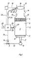
- a heat source 1 has a housing 2, in the interior 3 of which a lamella heat exchanger 4 is provided.
- the housing 2 has at its lower end 5 an inlet air opening, in the area of which a gas burner 6 is arranged, which has a plurality of injectors 7, which is fed by a corresponding plurality of gas nozzles 8 from a gas line 10 provided with a gas valve 9.
- the gas valve 9 is actuated by an actuator 11, the gas valve can assume a closed position and a maximum opening position as well as any possible intermediate position.
- the housing merges into an exhaust duct 13, which is provided with a flow safety device 14, which is followed by an exhaust pipe 15, in which there is a shut-off element 16, which can be rotated by a motor 17 via an actuating shaft 18 from a closed position over a possible variety of opening positions up to a maximum opening position.
- a cam 19 is attached to the shaft 18, which is adjusted relative to the shut-off element 16 in such a way that in an over-ignition position of the cams 19 actuates a contact of a microswitch 20 which is connected to a control device 22 via lines 21.
- the over-ignition position is to be understood as the position of the shut-off element of the gas valve 9 in which so much gas reaches the burner that the burner generates flames at all combustion slots.
- the associated position of the exhaust flap must cause the combustion gas generated to be removed after passing through the heat exchanger, without too much air being sucked in at the lower end 5 of the housing 2 by the suction effect in the exhaust duct 15 and being transported through the heat exchanger.
- the control device 22 is connected via a control line 23 to the motor 17 and via a control line 24 to the servomotor 11.
- Measuring lines 25 lead to a temperature sensor 26, which is arranged in a recess 27 on the side casing of the housing 2 approximately halfway between the burner and the heat exchanger. The sensor 26 is at a distance from the opening.
- Connections 28 serve to supply the control device from a power supply unit.
- the control device 22 is the individual subject of FIG. 2: It has a housing 30 which has an inlet chamber 31 and an outlet chamber 32 in the course of the gas line 10. Between the inlet and outlet chamber there is a valve seat 33 which can be closed in the idle state by a valve body 9 which is articulated by a rod 34 and which is under the restoring force of a compression spring 36, the continuous rod 34 with a diaphragm plate 37 being a rule Membrane 11 is connected, which is clamped pressure-tight in the housing 30 in the region of the outlet chamber 32 at its edge.
- the inlet and outlet chambers are thus separated from one another in the idle state via the closed valve 33, 9.
- the membrane divides a further chamber 39, which leads via a channel 40 to a valve center space 41.
- the valve center space 41 is delimited by two valve seats 42 and 43 and an outflow opening 44.
- a pilot gas line 35 branches off from the gas line 10 and leads to a pilot burner (not shown). Furthermore, in the course of the gas line 10, also upstream of the inlet chamber 31, a valve seat 38 is provided which is controlled by a valve body 100. This valve body is controlled by a compression spring 101, which is supported with respect to the housing 30. An actuating rod 102 engages on the valve body 100 and leads to a water switch 103, the housing of which is firmly connected to the housing 30. The inside of the water switch has a membrane 104 which is engaged by a membrane plate 105 which is connected to the rod 102.
- the two pressure chambers divided by the membrane 104 in the interior of the water switch are connected to a flow pressure sensor in the circulation circuit of the water heater or in the tap water path of the water heater, the water switch 103 forms, together with the valve 100/38, a lack of water protection.
- a channel 45 leads from the valve seat 43 to a branching point 46, from which a further channel 47 leads to the outlet chamber 32.
- Another channel 48 leads to a membrane chamber 49, which is connected to the outflow opening 44 via a line 50, in which a valve seat 51 is provided.
- a valve body 52 corresponds to the valve seat 51, which can be moved in the open position by a compression spring 53 which is supported with respect to the housing 30.
- the valve body 52 is applied to a membrane 54 which is under the action of a compression spring 55 which is actuated by an adjusting screw 56 Is adjustable, which in turn is gastight in a thread in the housing 30.
- a further membrane chamber 57 is formed, which is connected via an opening 58 to a further membrane chamber 59.
- this membrane chamber is delimited by a membrane 60, which forms a further membrane chamber 61 on the side facing away from the membrane chamber 59, in which a compression spring 62 is mounted, which is supported against an adjusting screw 63, which is gas-tight in one in the housing Thread is guided.
- the membrane chamber 61 is connected to the atmosphere via a calibrated bore 64.
- a valve body 74 which corresponds to a valve seat 75 arranged in the housing 30, is applied to the membrane 60.
- the valve seat 75 is connected to the membrane chamber 59 via a line 76.
- the valve body 74 is under the action of a compression spring 77, which is supported with respect to the housing 30 and tends to lift the valve body 74 from its valve seat 75.
- the valve seat 75 is adjoined by a chamber 78, which is connected to the membrane chamber 59 via a bore 79 of relatively small cross-section and via an air filter bore 80 to the atmosphere via an air filter 81.
- the chamber 78 Via a suction line 82, the chamber 78 is connected to the suction port of a diaphragm pump 83, which is driven by a motor 73, not shown, via a shaft 84.
- the motor in turn, can be supplied with voltage or electrical power by an actuator in order to ensure a certain drive behavior of the motor.
- the diaphragm pump has a pressure line 85 from which the actuating line 23 branches off.
- the pressure line 85 is connected to the diaphragm chamber 59 via a throttle bore 86.
- the valve seat 42 is controlled by a valve body 65 which is connected to an actuating rod 66.
- a two-armed lever 67 which is rotatably mounted about a pivot point 68 in the housing, engages on the adjusting rod 66.
- a return spring 69 brings the lever into the rest position shown and ensures that the valve body 65 rests on the valve seat 42 in the idle state.
- An electromagnet 70 which cooperates with an armature 71, which is part of the two-armed lever 67, is fastened to the housing 30.
- the electromagnet 70 can be supplied with electrical energy via a line 72.
- the line 23 leads to a housing 87 in which the servomotor 17 and a further servomotor 88 with a membrane 109 and an actuating pin 110 acting on the lever 94 are arranged.
- the servomotor 17 has two pressure chambers 89 and 90 within the housing 87, which are separated by a diaphragm 91 which is connected to a diaphragm plate 92 to which an actuating rod 93 engages, which is connected to a two-armed lever 94 which is connected to one Pivot 95 is rotatable.
- a compression spring 96 is used for resetting, it is supported against the housing 30.
- the pivot point 95 can be located on the housing 30.
- the lever 94 has on one end a toothing 97 which cooperates with a gear 98, the gear 98 being fixed on the shaft 18.
- the toothing 97 thus forms the one lever arm 99 of the lever 94.
- the other lever arm 106 is connected to the adjusting rod 93 and has the cam 19 at its end.
- the electromagnet 70 is arranged in a space 107 which is connected to the inlet chamber 31 via a bore 108.
- the control device just described has the following function: starting from the idle state shown in the drawing, the valve seat 33 is ver through the valve body 9 under the expansion effect of the compression spring 36 closed, that is, the connection between the gas inlet and gas outlet is interrupted.
- the diaphragm pump 83 is in the rest position, pressure and suction lines 85 and 82 do not have any differential pressure with respect to one another.
- the valves 42/65, 52/51 and 74/75 are closed, the electromagnet 70 is de-energized.
- the gas supply to the burner 6 is interrupted.
- the electromagnet 70 is supplied with electrical voltage via the line 72. This leads to a lifting of the valve body 65 from the valve seat 42.
- the pressure is also present via the opened valve 65/42 and the channel 40 in the chamber 39, so that the membrane 11 rises against the restoring force of the spring 36 and thus raises the valve body 9 from the valve seat 33.
- This lifting position of the valve body 9 leads to the so-called over-ignition position, here so much gas is passed through the gas line 10 that the connected burner of the heat source forms flames at all combustion slots. Due to the backflow effect of the combustion slots, the gas pressure of the chamber 32 is present via the line 10 in the membrane chamber 89, so that the membrane 91 is lifted against the restoring force of the spring 96 and the lever 94 is pivoted about the pivot point 95. This pivoting movement leads to a deflection of the shut-off valve 16, which changes from its closed position to the over-ignition position. This ignition position is exclusively dependent on the gas pressure behind the fitting 22.
- the cam 19 acts on the microswitch 20, so that the motor 73 of the diaphragm pump can only be energized after the ignition position has been reached.
- the actuation of the microswitch 20 also has the consequence that the heating element of a bimetallic safety switch (both not shown), which was also switched on when heat was requested, is again disconnected from the voltage.
- the bimetallic safety switch controls the power supply to the magnet 70 and to the diaphragm pump motor 73, so that the associated opening position of the shut-off device 16 is also monitored.
- the pressure supplied by the diaphragm pump is limited by the diaphragm 60, which is movable against the restoring force of the spring 62. If the pressure in the diaphragm chamber 59 exceeds the limit value, the diaphragm 60 pulls the valve body 74 off its seat 75 and short-circuits the suction and pressure side of the diaphragm pump. This valve 74/75 acts in conjunction with the membrane 60 as a maximum pressure limiter.
- the pressure in the membrane chamber 59 is also present in the membrane chamber 57. An increasing air pressure there leads to a throttling of the valve 52/51.
- valve body 65 Since the valve body 65 already rests on the valve seat 43, closing the valve body 52 causes a load on the membrane chamber 39, so that the valve body 9 moves in the direction of opening the valve seat 33.
- the valve 52/51 thus acts in conjunction with the membrane 54 as a continuous setpoint generator for the gas throughput.
- the tracking of the exhaust flap in a gas throughput mode between the maximum output and the overfiring output is monitored by the temperature sensor 26: If the shut-off element has an opening position that is smaller than the corresponding gas throughput to achieve optimal combustion or an optimal air excess, the interior sinks 3 of the heat source 1 of the exhaust gas level and exhaust gas escaping causes the temperature sensor 26 to respond. A response of the temperature sensor 26 leads to a lockout via the control device 22.
- the motor 73 of the diaphragm pump 83 is de-energized. This leads to the pressure line 85 becoming depressurized and the shut-off valve 16 turning back until the over-ignition position is reached. Furthermore, this leads to the fact that only the over-ignition gas throughput reaches the burner through the valve 9/33. If the device is now to be shut down completely, the operating voltage is removed from line 72. As a result, the electromagnet 70 is de-energized, so that the valve body 65 lifts off the valve seat 43 and closes the valve seat 42. As a result, the diaphragm chamber 39 is depressurized, so that the spring 36 pulls the valve body fully into the closed position on the seat 33.
- the gas supply is thus interrupted, the depressurization of the gas line 10 behind the armature 22 leads to a resetting of the diaphragm 91 due to the restoring force of the spring 96.
- the cam 19 thus leaves the microswitch 20 and the exhaust flap 16 goes into the closed position. The device has gone out.
Abstract
Description
Die vorliegende Erfindung bezieht sich auf ein Verfahren zum Betreiben einer brennstoffbeheizten Wärmequelle gemäß dem Oberbegriff des Anspruchs.The present invention relates to a method for operating a fuel-heated heat source according to the preamble of the claim.
Aus der DE-C-1 013027 ist eine brennstoffbeheizte Wärmequelle der oben genannten Gattung bekanntgeworden, bei der aber nicht bei Öffnungsstellungen zwischen einer Überzünd-und einer Volloffenstellung unterschieden wird und bei der insbesondere das Absperrorgan in seinen Stellungen nicht überwacht wird.From DE-C-1 013027 a fuel-heated heat source of the above-mentioned type has become known, in which, however, no distinction is made between an over-ignition and a fully open position in open positions and in which the shut-off device in particular is not monitored in its positions.
Weiterhin ist durch die nicht zum Stand der Technik gehörige DE-A-3 007 214 eine Armatur zur Steuerung des Betriebsverhaltens einer brennstoffbeheizten Wärmequelle bekanntgeworden, bei der über eine Membranpumpe ein Servodruck vorgegeben wird, der auf eine Reglermembran einwirkt, die unmittelbar mit einem Brennstoffventil verbunden ist. Je größer somit über die variable elektrische Beaufschlagung der Membranpumpe der Servodruck ist, um so größer ist auch der Öffnungsgrad des Brennstoffventils. Bei der brennstoffbeheizten Wärmequelle gemäß der älteren Patentanmeldung ist nun aber nicht vorgesehen, die Wärmequelle selbst zuluft- oder abgasseitig durch ein Absperrorgan abzusperren, und es ist weiterhin nicht daran gedacht, die Stellung dieses Absperrorganes zu überwachen. Schließlich ist es auch nicht vorgesehen, die Brennstoffzufuhr mit der Stellung des Absperrorgans zu koppeln, um den Luftüberschuß über die ganze Variation der von der Wärmequelle erzielbaren thermischen Leistung konstantzuhalten.Furthermore, DE-A-3 007 214, which is not part of the prior art, has disclosed a fitting for controlling the operating behavior of a fuel-heated heat source, in which a servo pressure is specified via a diaphragm pump, which acts on a regulator diaphragm which is directly connected to a fuel valve is. The greater the variable servo pressure applied to the diaphragm pump, the greater the degree of opening of the fuel valve. In the case of the fuel-heated heat source according to the older patent application, however, it is now not intended to shut off the heat source itself on the supply or exhaust side by means of a shut-off device, and it is also not intended to monitor the position of this shut-off device. Finally, there is also no provision for coupling the fuel supply to the position of the shut-off element in order to keep the excess air constant over the entire variation of the thermal power achievable by the heat source.
Der vorliegenden Erfindung liegt somit die Aufgabe zugrunde, das Verhältnis von zugeführter Luft und Brennstoff vom Überzündvorgang bis zur Vollast konstanzuhalten.The present invention is therefore based on the object of keeping the ratio of supplied air and fuel constant from the ignition process to full load.
Das Verfahren, mit dem die Aufgabe gelöst wird, ist aus dem kennzeichnenden Teil des Anspruchs 1 ersichtlich.The method with which the object is achieved can be seen from the characterizing part of
Der mit der Erfindung erzielbare technische Fortschritt ist darin zu sehen, daß eine Überwachung der Stellung des Absperrorgans vorgesehen ist und daß erst nach Erreichen der vorgegebenen Stellung des Absperrorgans die über die Überzündstellung hinausgehenden möglichen Stellungen des Brennstoffventils freigegeben werden und daß das Brennstoffventil kontinuierlich der variierenden Leistung der Wärmequelle nachgefahren wird.The technical progress achievable with the invention can be seen in the fact that monitoring of the position of the shut-off element is provided and that only after reaching the predetermined position of the shut-off element the possible positions of the fuel valve which go beyond the ignition position are released and that the fuel valve continuously varies in performance the heat source is traced.
Schließlich ist noch eine Überwachung des Abgases über den Abgaspegel innerhalb der Wärmequelle vorhanden, so daß bei Überschreiten eines gewissen Grenzwertes von produziertem Abgas eine Stillsetzung der Wärmequelle durch Unterbinden weiterer Brennstoffzufuhr stattfindet.Finally, there is still a monitoring of the exhaust gas via the exhaust gas level within the heat source, so that when a certain limit value of the produced exhaust gas is exceeded, the heat source is stopped by preventing further fuel supply.
Ein Ausführungsbeispiel der Erfindung wird anhand der Fig. 1 und 2 der Zeichnungen näher erläutert. Es zeigt
- Fig. 1 eine Prinzipdarstellung einer brennstoffbeheizten Wärmequelle und
- Fig. 2 Details der Armatur und der Steuer- und Regelglieder.
- Fig. 1 is a schematic diagram of a fuel-heated heat source and
- Fig. 2 details of the valve and the control elements.
In beiden Figuren bedeuten gleiche Bezugszeichen jeweils die gleichen Einzelheiten.In both figures, the same reference numerals denote the same details.
Eine Wärmequelle 1 weist ein Gehäuse 2 auf, in dessen Innenraum 3 ein Lamellenwärmetauscher 4 vorgesehen ist. Das Gehäuse 2 weist an seinem unteren Ende 5 eine Zuluftöffnung auf, in deren Bereich ein Gasbrenner 6 angeordnet ist, der eine Vielzahl von Injektoren 7 aufweist, die von einer entsprechenden Vielzahl von Gasdüsen 8 aus einer mit einem Gasventil 9 versehenen Gasleitung 10 gespeist ist. Das Gasventil 9 wird von einem Stellmotor 11 betätigt, das Gasventil kann eine Schließstellung und eine Maximalöffnungsstellung sowie jede mögliche Zwischenstellung einnehmen.A
Am oberen Ende 12 geht das Gehäuse in einen Abgasschacht 13 über, der mit einer Strömungssicherung 14 versehen ist, der ein Abgasrohr 15 nachgeschaltet ist, in dem sich ein Absperrorgan 16 befindet, das von einem Motor 17 über eine Stellwelle 18 verdrehbar ist von einer Schließstellung über eine mögliche Vielzahl von Öffnungsstellungen bis zu einer Maximalöffnungsstellung.At the
An der Welle 18 ist ein Nocken 19 angebracht, der so gegenüber dem Absperrorgan 16 justiert ist, daß in einer Überzündstellung der Nocken 19 einen Kontakt eines Mikroschalters 20 betätigt, der über Leitungen 21 mit einer Steuereinrichtung 22 verbunden ist. Als Überzündstellung ist die Stellung des Absperrorgans des Gasventils 9 zu verstehen, bei der so viel Gas zum Brenner gelangt, daß der Brenner Flammen an allen Brennschlitzen erzeugt. Die zugehörige Stellung der Abgasklappe muß bewirken, daß das erzeugte Verbrennungsgas nach Durchsetzen des Wärmetauschers abgeführt wird, ohne daß durch die Sogwirkung im Abgasschacht 15 zuviel Luft am unteren Ende 5 des Gehäuses 2 angesaugt und durch den Wärmetauscher transportiert wird.A
Die Steuervorrichtung 22 ist über eine Stelleitung 23 mit dem Motor 17 und über eine Stelleitung 24 mit dem Stellmotor 11 verbunden. Meßleitungen 25 führen zu einem Temperaturfühler 26, der in einer Ausnehmung 27 am Seitenmantel des Gehäuses 2 etwa auf halber Höhe zwischen Brenner und Wärmetauscher angeordnet ist. Der Fühler 26 steht im Abstand von der Öffnung.The
Anschlüsse 28 dienen zur Versorgung der Steuervorrichtung von einem Netzteil.
Die Steuervorrichtung 22 ist im einzelnen Gegenstand der Fig. 2: Sie weist ein Gehäuse 30 auf, das im Zuge der Gasleitung 10 eine Einlaßkammer 31 und eine Auslaßkammer 32 aufweist. Zwischen Ein- und Auslaßkammer befindet sich ein Ventilsitz 33, der von einem von einer Stange 34 angelenkten Ventilkörper 9, der unter der Rückstellkraft einer Druckfeder 36 steht, im Ruhezustand verschließbar ist, wobei die Stetistange 34 mit einem Membranteller 37 einer Regelmembran 11 verbunden ist, die im Bereich der Auslaßkammer 32 an ihrem Rand druckdicht im Gehäuse 30 eingespannt ist. Ein- und Auslaßkammer sind somit im Ruhezustand über das verschlossene Ventil 33, 9 voneinander getrennt. Die Membran teilt eine weitere Kammer 39 ab, die über einen Kanal 40 zu einem Ventilmittelraum 41 führt. Der Ventilmittelraum 41 ist über zwei Ventilsitze 42 und 43 sowie eine Abströmöffnung 44 begrenzt.The
Von der Gasleitung 10 zweigt eine Zündgasleitung 35 ab, die zu einem nicht weiter dargestellten Zündbrenner führt. Weiterhin ist im Zuge der Gasleitung 10, auch der Einlaßkammer 31 vorgeschaltet, ein Ventilsitz 38 vorgesehen, der von einem Ventilkörper 100 beherrscht ist. Dieser Ventilkörper ist von einer Druckfeder 101 gesteuert, die sich gegenüber dem Gehäuse 30 abstützt. An den Ventilkörper 100 greift eine Stellstange 102 an, die zu einem Wasserschalter 103 führt, dessen Gehäuse mit dem Gehäuse 30 fest verbunden ist. Der Wasserschalter weist in seinem Inneren eine Membran 104 auf, an der ein Membranteller 105 angreift, der mit der Stange 102 verbunden ist.A
Die beiden durch die Membran 104 abgeteilten Druckkammern im Inneren des Wasserschalters sind mit einem Fließdruckgeber im Umlaufkreis des Wasserheizers oder im Zapfwasserweg des Wasserheizers verbunden, der Wasserschalter 103 bildet zusammen mit dem Ventil 100/38 eine Wassermangelsicherung.The two pressure chambers divided by the
Vom Ventilsitz 43 führt ein Kanal 45 zu einer Verzweigungsstelle 46, von der ein weiterer Kanal 47 zur Auslaßkammer 32 führt. Ein weiterer Kanal 48 führt zu einer Membrankammer 49, die über eine Leitung 50, in der ein Ventilsitz 51 vorgesehen ist, mit der Abströmöffnung 44 verbunden ist. Mit dem Ventilsitz 51, der von einer sich gegenüber dem Gehäuse 30 abstützenden Druckfeder 53 in Öffnungsstellung bewegbar ist, korrespondiert ein Ventilkörper 52. Der Ventilkörper 52 ist an einer Membran 54 angelegt, die unter der Wirkung einer Druckfeder 55 steht, die von einer Stellschraube 56 justierbar ist, die ihrerseits in einem Gewinde im Gehäuse 30 gasdicht geführt ist.A
Auf der der Membrankammer 49 abgewandten Seite der Membran 54 ist eine weitere Membrankammer 57 gebildet, die über eine Öffnung 58 mit einer weiteren Membrankammer 59 in Verbindung steht. Diese Membrankammer wird außer von dem Gehäuse 30 von einer Membran 60 begrenzt, die auf der der Membrankammer 59 abgewandten Seite eine weitere Membrankammer 61 bildet, in welcher eine Druckfeder 62 gelagert ist, die sich gegenüber einer Einstellschraube 63 abstützt, die im Gehäuse gasdicht in einem Gewinde geführt ist. Die Membrankammer 61 ist über eine kalibrierte Bohrung 64 mit der Atmosphäre verbunden.On the side of the
An die Membran 60 ist ein Ventilkörper 74 angelegt, der mit einem im Gehäuse 30 angeordneten Ventilsitz 75 korrespondiert. Der Ventilsitz 75 steht über eine Leitung 76 mit der Membrankammer 59 in Verbindung. Der Ventilkörper 74 steht unter der Wirkung einer Druckfeder 77, die sich gegenüber dem Gehäuse 30 abstützt und das Bestreben hat, den Ventilkörper 74 von seinem Ventilsitz 75 abzuheben. Auf der anderen Seite der Leitung 76 schließt sich an den Ventilsitz 75 eine Kammer 78 an, die über eine Bohrung 79 relativ kleinen Querschnitts mit der Membrankammer 59 und über eine Zuluftbohrung 80 über einen Luftfilter 81 mit der Atmosphäre verbunden ist. Über eine Ansaugleitung 82 ist die Kammer 78 mit dem Saugstutzen einer Membranpumpe 83 verbunden, die über eine Welle 84 von einem nicht dargestellten Motor 73 angetrieben ist. Der Motor seinerseits ist von einem Stellglied mit Spannung beziehungsweise elektrischer Leistung beaufschlagbar, um ein bestimmtes Antriebsverhalten des Motors zu gewährleisten. Die Membranpumpe weist eine Druckleitung 85 auf, von der die Stelleitung 23 abzweigt. Die Druckleitung 85 steht über eine Drosselbohrung 86 mit der Membrankammer 59 in Verbindung.A
Der Ventilsitz 42 ist von einem Ventilkörper 65 beherrscht, der mit einer Stellstange 66 verbunden ist. An die Stellstange 66 greift ein zweiarmiger Hebel 67 an, der um einen Drehpunkt 68 im Gehäuse drehbar gelagert ist. Eine Rückstellfeder 69 bringt den Hebel in die dargestellte Ruhelage und sorgt dafür, daß der Ventilkörper 65 auf dem Ventilsitz 42 im Ruhezustand aufliegt. Am Gehäuse 30 ist ein Elektromagnet 70 befestigt, der mit einem Anker 71 zusammenwirkt, der Teil des zweiarmigen Hebels 67 ist.The
Der Elektromagnet 70 ist über eine Leitung 72 mit elektrischer Energie versorgbar.The
Die Leitung 23 führt zu einem Gehäuse 87, in dem der Stellmotor 17 und ein weiterer Stellmotor 88 mit einer Membran 109 und einem auf den Hebel 94 einwirkenden Stellstift 110 angeordnet sind. Der Stellmotor 17 weist innerhalb des Gehäuses 87 zwei Druckkammern 89 und 90 auf, die von einer Membran 91 getrennt sind, die mit einem Membranteller 92 verbunden ist, an dem eine Stellstange 93 angreift, die mit einem zweiarmigen Hebel 94 verbunden ist, der um einen Drehpunkt 95 drehbar ist. Eine Druckfeder 96 dient der Rückstellung, sie stützt sich gegenüber dem Gehäuse 30 ab.The
Der Drehpunkt 95 kann sich am Gehäuse 30 befinden. Der Hebel 94 weist auf seinem einen Ende eine Verzahnung 97 auf, die mit einem Zahnrad 98 zusammenwirkt, wobei das Zahnrad 98 auf der Welle 18 befestigt ist. Die Verzahnung 97 bildet somit den einen Hebelarm 99 des Hebels 94. Der andere Hebelarm 106 ist mit der Stellstange 93 verbunden und weist an seinem Ende den Nocken 19 auf.The pivot point 95 can be located on the
Der Elektromagnet 70 ist in einem Raum 107 angeordnet, der über eine Bohrung 108 mit der Einlaßkammer31 verbunden ist.The
Die eben beschriebene Steuervorrichtung hat folgende Funktion: Ausgehend von dem in der Zeichnung dargestellten Ruhezustand ist der Ventilsitz 33 durch den Ventilkörper 9 unter der Ausdehnungswirkung der Druckfeder 36 verschlossen, das heißt, die Verbindung zwischen Gaseinlaß und Gasauslaß ist unterbrochen. Die Membranpumpe 83 ist in Ruhestellung, Druck-und Saugleitung 85 beziehungsweise 82 weisen zueinander keinen Differenzdruck auf. Die Ventile 42/65, 52/51 und 74/75 sind geschlossen, der Elektromagnet 70 ist stromlos. Die Gaszufuhr zu dem Brenner 6 ist unterbrochen.The control device just described has the following function: starting from the idle state shown in the drawing, the
Wird nun mehr Gas am Brenner verlangt, so wird der Elektromagnet 70 über die Leitung 72 mit elektrischer Spannung beaufschlagt. Das führt zu einem Abheben des Ventilkörpers 65 vom Ventilsitz 42. Somit steht (nachdem sich unter dem Einfluß der laufenden Umwälzpumpe im Wasserschalter 103 ein Druck aufgebaut hat und das Ventil 100/38 geöffnet hat) Gasdruck aus der Gasleitung über die Bohrung 108 im Operatorraum 107 an. Der Druck steht aber auch über das geöffnete Ventil 65/42 und den Kanal 40 in der Kammer 39 an, so daß sich die Membran 11 gegen die Rückstellkraft der Feder 36 anhebt und so den Ventilkörper 9 vom Ventilsitz 33 anhebt. Diese Abhebestellung des Ventilkörpers 9 führt zur sogenannten Überzündstellung, hier wird durch die Gasleitung 10 so viel Gas durchgesetzt, daß der angeschlossene Brenner der Wärmequelle an allen Brennschlitzen Flammen bildet. Durch die Rückstauwirkung der Brennschlitze steht der Gasdruck der Kammer 32 über die Leitung 10 in der Membrankammer 89 an, so daß die Membran 91 gegen die Rückstellkraft der Feder 96 abgehoben wird und der Hebel 94 um den Drehpunkt 95 verschwenkt wird. Diese Schwenkbewegung führt zu einem Auslenken des Absperrogans 16, das von seiner Schließlage in die Überzündstellung übergeht. Diese Überzündstellung ist ausschließlich abhängig vom Gasdruck hinter der Armatur 22. In der Überzündstellung beaufschlagt der Nocken 19 den Mikroschalter 20, so daß erst nach Erreichen der Überzündstellung der Motor 73 der Membranpumpe erregt werden kann. Die Betätigung des Mikroschalters 20 hat weiterhin zur Folge, daß das Beheizungselement eines Bimetallsicherheitsschalters (beide nicht dargestellt), welches bei Wärmeanforderung mit eingeschaltet wurde, wieder von Spannung getrennt wird. Der Bimetallsicherheitsschalter beherrscht die Stromzufuhr zum Magnet 70 und zum Membranpumpenmotor 73, so daß die zugehörige Öffnungsstellung des Absperrogans 16 ebenfalls überwacht ist.If more gas is now required at the burner, the
Wird nun Wärmeleistung von einem Raum-oder Vorlaufthermostaten oder einem Gebrauchswasserbereiter angefordert, resultiert eine elektrische Beaufschlagung des Motors 73, so daß die Membranpumpe 83 zu fördern beginnt. Somit steht erhöhter Luftdruck über die Druckleitung 85 sowohl an der Druckleitung 23 als auch in der Membrankammer 59 an. Die Höhe dieses Druckes ist abhängig von der angeforderten Wärmeleistung. Somit findet eine Auslenkung der Membran 109 im Stellmotor 88 statt, so daß der Stellstift 110 den Hebel 94 im gleichen Sinne wie den Stellstift 93 weiterverstellt. Die Folge davon ist eine Weiterführung der Stellung des Absperrorgans 16, der Öffnungswinkel des Absperrorgans in der Abgasleitung ist um so größer, je größer der von der Membranpumpe gelieferte Druck ist. Der Druck, der von der Membranpumpe geliefert wird, wird begrenzt durch die Membran 60, die gegen die Rückstellkraft der Feder 62 beweglich ist. Überschreitet der Druck in der Membrankammer 59 den Grenzwert, so zieht die Membran 60 den Ventilkörper 74 von seinem Sitz 75 ab und schließt Saug- und Druckseite der Membranpumpe kurz. Dieses Ventil 74/75 wirkt in Verbindung mit der Membran 60 als Maximaldruckbegrenzer.If heat output is now requested from a room thermostat or flow thermostat or a water heater, the
Der Druck in der Membrankammer 59 steht aber auch in der Membrankammer 57 an. Ein dort steigender Luftdruck führt zu einem Drosseln des Ventils 52/51.The pressure in the
Da der Ventilkörper 65 bereits auf dem Ventilsitz 43 aufliegt, bewirkt ein Schließen des Ventilkörpers 52 eine Belastung der Membrankammer 39, so daß sich der Ventilkörper 9 in Richtung Öffnen des Ventilsitzes 33 bewegt. Das Ventil 52/51 wirkt also in Verbindung mit der Membran 54 als kontinuierlicher Sollwertgeber für den Gasdurchsatz.Since the valve body 65 already rests on the
Das Nachführen der Abgasklappe in einem Gasdurchsatzbetrieb zwischen der Maximalleistung und der Überzündleistung wird durch den Temperaturfühler 26 überwacht: Weist das Absperrorgan eine Öffnungsstellung auf, die kleiner ist als die dem entsprechenden Gasdurchsatz zugehörige zur Erzielung einer optimalen Verbrennung beziehungsweise eines optimalen Luftüberschusses, so sinkt im Innenraum 3 der Wärmequelle 1 der Abgasspiegel und austretendes Abgas bringt den Temperaturfühler 26 zum Ansprechen. Ein Ansprechen des Temperaturfühlers 26 führt zu einer Störabschaltung über die Steuervorrichtung 22.The tracking of the exhaust flap in a gas throughput mode between the maximum output and the overfiring output is monitored by the temperature sensor 26: If the shut-off element has an opening position that is smaller than the corresponding gas throughput to achieve optimal combustion or an optimal air excess, the interior sinks 3 of the
Soll das Gerät stillgesetzt werden, so wird der Motor 73 der Membranpumpe 83 spannungslos geschaltet. Das führt zu einem Druckloswerden der Druckleitung 85 und zu einem Rückdrehen des Absperrogans 16, bis die Überzündstellung erreicht ist. Weiterhin führt dies dazu, daß durch das Ventil 9/33 nur der Überzündgasdurchsatz zum Brenner gelangt. Soll das Gerät nunmehr ganz stillgesetzt werden, so wird die Betriebsspannung von der Leitung 72 abgenommen. Als Folge davon wird der Elektromagnet 70 stromlos, so daß der Ventilkörper 65 vom Ventilsitz 43 abhebt und den Ventilsitz 42 verschließt. Als Folge davon wird die Membrankammer 39 drucklos, so daß die Feder 36 den Ventilkörper voll in Schließstellung auf den Sitz 33 zieht. Damit ist die Gaszufuhr unterbrochen, das Druckloswerden der Gasleitung 10 hinter der Armatur 22 führt zu einem Rückstellen der Membran 91 aufgrund der Rückstellkraft der Feder 96. Somit wird der Nocken 19 den Mikroschalter 20 verlassen, und die Abgasklappe 16 geht in die Schließstellung. Das Gerät ist erloschen.If the device is to be stopped, the
Claims (1)
- A process of operating a fuel-heated heat source (1) comprising a burner (6), which is fed from a fuel valve (9), a heat exchanger (4) and a shut-off valve (16) which is operable by controller (23) and controls the stream of air or exhaust gas flowing through the heat source, characterized in that the shut-off valve (16) is shifted by the fuel pressure from its closed position to its ignition transfer position and the fuel valve (9) is opened further when that position has been reached, the shifting of the shut-off valve from its ignition transfer position to its fully open position is effected by a servo pressure (83, 85), which also determines the position of the fuel valve (9), and the last-mentioned position of the shut-off valve is monitored by a heat sensor (26), which is responsive to the level of the exhaust gas in the heat source (1).
Priority Applications (1)
| Application Number | Priority Date | Filing Date | Title |
|---|---|---|---|
| AT81101963T ATE12828T1 (en) | 1980-03-25 | 1981-03-17 | METHOD OF OPERATING A FUEL HEATED HEAT SOURCE. |
Applications Claiming Priority (2)
| Application Number | Priority Date | Filing Date | Title |
|---|---|---|---|
| DE8008123 | 1980-03-25 | ||
| DE8008123U | 1980-03-25 |
Publications (3)
| Publication Number | Publication Date |
|---|---|
| EP0036610A2 EP0036610A2 (en) | 1981-09-30 |
| EP0036610A3 EP0036610A3 (en) | 1981-11-25 |
| EP0036610B1 true EP0036610B1 (en) | 1985-04-17 |
Family
ID=6714112
Family Applications (1)
| Application Number | Title | Priority Date | Filing Date |
|---|---|---|---|
| EP81101963A Expired EP0036610B1 (en) | 1980-03-25 | 1981-03-17 | Method of energizing a fuel-heated heat source |
Country Status (2)
| Country | Link |
|---|---|
| EP (1) | EP0036610B1 (en) |
| AT (1) | ATE12828T1 (en) |
Families Citing this family (3)
| Publication number | Priority date | Publication date | Assignee | Title |
|---|---|---|---|---|
| EP0103303A3 (en) * | 1982-09-15 | 1984-06-06 | Joh. Vaillant GmbH u. Co. | Fuel-heated heat source |
| HU230446B1 (en) * | 2010-04-15 | 2016-06-28 | Lajos Tamás Pólya | Apparatus to reduce gas consumption for single heating equipments primarily for gas convectors and gas fires |
| IT1403351B1 (en) * | 2010-12-21 | 2013-10-17 | Sit La Precisa Spa Con Socio Unico | DEVICE FOR CONTROLLING THE DISTRIBUTION OF A FUEL GAS TOWARDS A BURNER, PARTICULARLY FOR WATER HEATERS |
Family Cites Families (5)
| Publication number | Priority date | Publication date | Assignee | Title |
|---|---|---|---|---|
| US4084743A (en) * | 1976-09-27 | 1978-04-18 | Johnson Controls, Inc. | Interlock arrangement for a stack damper control |
| US4164936A (en) * | 1977-08-18 | 1979-08-21 | Dottore Jr Nicholas J | Damper |
| US4185769A (en) * | 1977-09-12 | 1980-01-29 | Nezworski James E | Exhaust flue damper and control system therefor |
| US4189296A (en) * | 1978-03-13 | 1980-02-19 | Johnson Controls, Inc. | Method and apparatus for controlling furnace |
| DE3007214C2 (en) * | 1979-03-10 | 1983-11-10 | Joh. Vaillant Gmbh U. Co, 5630 Remscheid | Gas pressure regulator for a gas-heated circulating water heater with a utility water heater |
-
1981
- 1981-03-17 EP EP81101963A patent/EP0036610B1/en not_active Expired
- 1981-03-17 AT AT81101963T patent/ATE12828T1/en not_active IP Right Cessation
Also Published As
| Publication number | Publication date |
|---|---|
| EP0036610A2 (en) | 1981-09-30 |
| EP0036610A3 (en) | 1981-11-25 |
| ATE12828T1 (en) | 1985-05-15 |
Similar Documents
| Publication | Publication Date | Title |
|---|---|---|
| DE19722600C2 (en) | servo controller | |
| EP0957314B1 (en) | Control device for gas burners | |
| DE2749252C3 (en) | Actuating device for adjusting the closing piece of a valve | |
| EP0390964B1 (en) | Control device for gas burners | |
| EP0048486B1 (en) | Diaphragm-pressure regulator | |
| EP0036610B1 (en) | Method of energizing a fuel-heated heat source | |
| EP0035147B1 (en) | Gas pressure regulator | |
| EP0016326B1 (en) | Gas-pressure controller | |
| DE4440492A1 (en) | Continuous water heater | |
| DE3011374C2 (en) | ||
| EP0103303A2 (en) | Fuel-heated heat source | |
| DE2723178C2 (en) | Safety and control system for the air supply to the combustion chamber of a gas burner with forced draft | |
| DE3007214C2 (en) | Gas pressure regulator for a gas-heated circulating water heater with a utility water heater | |
| DE3114942A1 (en) | CONTROL DEVICE FOR THE GAS-FIRED BOILER OF A HOT WATER HEATING SYSTEM | |
| DE3333606A1 (en) | Fuel-heated heat source | |
| DE3000669C2 (en) | Gas pressure regulator | |
| DE3007215C2 (en) | Gas pressure regulator for a gas-heated circulating water heater with a domestic water heater | |
| DE3339518C2 (en) | Gas heated heat source | |
| EP0013993B1 (en) | Pressure controller | |
| EP0036613A1 (en) | Regulation apparatus for a gas-fired water or air heater which is controllable by a temperature sensor | |
| EP0108349A2 (en) | Gas-fired heat source | |
| DE2630414A1 (en) | Air supply control system for enclosed fireplace - ensures excess air over wide burner performance range | |
| DE3010737A1 (en) | Gas regulator for gas-fired burner - has auxiliary membrane drive operated by pressure regulator controlling air feed | |
| DE10209193C1 (en) | Electrically-controlled gas valve with regulating valve for compensating pressure variations on inlet side | |
| DE8005148U1 (en) | GAS PRESSURE REGULATOR |
Legal Events
| Date | Code | Title | Description |
|---|---|---|---|
| PUAI | Public reference made under article 153(3) epc to a published international application that has entered the european phase |
Free format text: ORIGINAL CODE: 0009012 |
|
| PUAL | Search report despatched |
Free format text: ORIGINAL CODE: 0009013 |
|
| AK | Designated contracting states |
Designated state(s): AT BE CH FR GB IT LI LU NL SE |
|
| AK | Designated contracting states |
Designated state(s): AT BE CH FR GB IT LI LU NL SE |
|
| 17P | Request for examination filed |
Effective date: 19811102 |
|
| RAP1 | Party data changed (applicant data changed or rights of an application transferred) |
Owner name: VAILLANT GMBH Owner name: SCHONEWELLE B.V. Owner name: VAILLANT LIMITED Owner name: VAILLANT GES.M.B.H Owner name: COFRABEL N.V. Owner name: JOH. VAILLANT GMBH U. CO |
|
| RAP1 | Party data changed (applicant data changed or rights of an application transferred) |
Owner name: VAILLANT GMBH Owner name: SCHONEWELLE B.V. Owner name: VAILLANT LIMITED Owner name: VAILLANT GES.M.B.H Owner name: VAILLANT S.A.R.L Owner name: COFRABEL N.V. Owner name: JOH. VAILLANT GMBH U. CO |
|
| RAP1 | Party data changed (applicant data changed or rights of an application transferred) |
Owner name: VAILLANT GMBH Owner name: SCHONEWELLE B.V. Owner name: VAILLANT LTD. Owner name: VAILLANT GES.M.B.H Owner name: VAILLANT S.A.R.L Owner name: COFRABEL N.V. Owner name: JOH. VAILLANT GMBH U. CO |
|
| ITF | It: translation for a ep patent filed |
Owner name: DE DOMINICIS & MAYER S.R.L. |
|
| GRAA | (expected) grant |
Free format text: ORIGINAL CODE: 0009210 |
|
| AK | Designated contracting states |
Designated state(s): AT BE CH FR GB IT LI LU NL SE |
|
| REF | Corresponds to: |
Ref document number: 12828 Country of ref document: AT Date of ref document: 19850515 Kind code of ref document: T |
|
| ET | Fr: translation filed | ||
| PLBE | No opposition filed within time limit |
Free format text: ORIGINAL CODE: 0009261 |
|
| STAA | Information on the status of an ep patent application or granted ep patent |
Free format text: STATUS: NO OPPOSITION FILED WITHIN TIME LIMIT |
|
| PGFP | Annual fee paid to national office [announced via postgrant information from national office to epo] |
Ref country code: AT Payment date: 19860326 Year of fee payment: 6 |
|
| 26N | No opposition filed | ||
| PG25 | Lapsed in a contracting state [announced via postgrant information from national office to epo] |
Ref country code: AT Effective date: 19870317 |
|
| ITTA | It: last paid annual fee | ||
| PGFP | Annual fee paid to national office [announced via postgrant information from national office to epo] |
Ref country code: SE Payment date: 19921207 Year of fee payment: 13 Ref country code: FR Payment date: 19921207 Year of fee payment: 13 |
|
| PGFP | Annual fee paid to national office [announced via postgrant information from national office to epo] |
Ref country code: LU Payment date: 19921209 Year of fee payment: 13 |
|
| PGFP | Annual fee paid to national office [announced via postgrant information from national office to epo] |
Ref country code: GB Payment date: 19921217 Year of fee payment: 13 |
|
| PGFP | Annual fee paid to national office [announced via postgrant information from national office to epo] |
Ref country code: BE Payment date: 19930208 Year of fee payment: 13 |
|
| EPTA | Lu: last paid annual fee | ||
| PGFP | Annual fee paid to national office [announced via postgrant information from national office to epo] |
Ref country code: CH Payment date: 19930324 Year of fee payment: 13 |
|
| PGFP | Annual fee paid to national office [announced via postgrant information from national office to epo] |
Ref country code: NL Payment date: 19930331 Year of fee payment: 13 |
|
| NLT1 | Nl: modifications of names registered in virtue of documents presented to the patent office pursuant to art. 16 a, paragraph 1 |
Owner name: VAILLANT B.V. TE AMSTERDAM. |
|
| PG25 | Lapsed in a contracting state [announced via postgrant information from national office to epo] |
Ref country code: LU Free format text: LAPSE BECAUSE OF NON-PAYMENT OF DUE FEES Effective date: 19940317 Ref country code: GB Effective date: 19940317 |
|
| PG25 | Lapsed in a contracting state [announced via postgrant information from national office to epo] |
Ref country code: SE Free format text: LAPSE BECAUSE OF NON-PAYMENT OF DUE FEES Effective date: 19940318 |
|
| PG25 | Lapsed in a contracting state [announced via postgrant information from national office to epo] |
Ref country code: LI Effective date: 19940331 Ref country code: CH Effective date: 19940331 Ref country code: BE Effective date: 19940331 |
|
| BERE | Be: lapsed |
Owner name: S.A. VAILLANT N.V. Effective date: 19940331 |
|
| PG25 | Lapsed in a contracting state [announced via postgrant information from national office to epo] |
Ref country code: NL Effective date: 19941001 |
|
| GBPC | Gb: european patent ceased through non-payment of renewal fee |
Effective date: 19940317 |
|
| NLV4 | Nl: lapsed or anulled due to non-payment of the annual fee | ||
| PG25 | Lapsed in a contracting state [announced via postgrant information from national office to epo] |
Ref country code: FR Effective date: 19941130 |
|
| REG | Reference to a national code |
Ref country code: CH Ref legal event code: PL |
|
| REG | Reference to a national code |
Ref country code: FR Ref legal event code: ST |
|
| EUG | Se: european patent has lapsed |
Ref document number: 81101963.7 Effective date: 19941010 |