EP0036337A2 - Sound reproducing system having sonic image localization networks - Google Patents
Sound reproducing system having sonic image localization networks Download PDFInfo
- Publication number
- EP0036337A2 EP0036337A2 EP81301165A EP81301165A EP0036337A2 EP 0036337 A2 EP0036337 A2 EP 0036337A2 EP 81301165 A EP81301165 A EP 81301165A EP 81301165 A EP81301165 A EP 81301165A EP 0036337 A2 EP0036337 A2 EP 0036337A2
- Authority
- EP
- European Patent Office
- Prior art keywords
- signals
- voltage
- listener
- loudspeakers
- dividing
- Prior art date
- Legal status (The legal status is an assumption and is not a legal conclusion. Google has not performed a legal analysis and makes no representation as to the accuracy of the status listed.)
- Granted
Links
Images


Classifications
-
- H—ELECTRICITY
- H04—ELECTRIC COMMUNICATION TECHNIQUE
- H04S—STEREOPHONIC SYSTEMS
- H04S5/00—Pseudo-stereo systems, e.g. in which additional channel signals are derived from monophonic signals by means of phase shifting, time delay or reverberation
- H04S5/02—Pseudo-stereo systems, e.g. in which additional channel signals are derived from monophonic signals by means of phase shifting, time delay or reverberation of the pseudo four-channel type, e.g. in which rear channel signals are derived from two-channel stereo signals
-
- H—ELECTRICITY
- H04—ELECTRIC COMMUNICATION TECHNIQUE
- H04S—STEREOPHONIC SYSTEMS
- H04S1/00—Two-channel systems
- H04S1/002—Non-adaptive circuits, e.g. manually adjustable or static, for enhancing the sound image or the spatial distribution
-
- H—ELECTRICITY
- H04—ELECTRIC COMMUNICATION TECHNIQUE
- H04S—STEREOPHONIC SYSTEMS
- H04S2400/00—Details of stereophonic systems covered by H04S but not provided for in its groups
- H04S2400/11—Positioning of individual sound objects, e.g. moving airplane, within a sound field
-
- H—ELECTRICITY
- H04—ELECTRIC COMMUNICATION TECHNIQUE
- H04S—STEREOPHONIC SYSTEMS
- H04S5/00—Pseudo-stereo systems, e.g. in which additional channel signals are derived from monophonic signals by means of phase shifting, time delay or reverberation
- H04S5/005—Pseudo-stereo systems, e.g. in which additional channel signals are derived from monophonic signals by means of phase shifting, time delay or reverberation of the pseudo five- or more-channel type, e.g. virtual surround
Definitions
- the present invention relates generally to sound reproducing systems, and in particular to a system for localizing sonic images in desired areas using two loudspeakers located in front of a listener.
- sonic images appear to originate in the area between two loudspeakers located in front of the listener.
- the signals carries information as to the direction and distance of sounds or sonic images with respect to the listener
- the sonic images are localized so that they are made to appear to originate from a point determined by the information carried by the input stereophonic signals.
- Monophonic signals which carries no localization information can also be localized when applied to two loudspeakers at a desired position by varying the relative amplitude of the signals applied to the speakers to the other.
- the localized images are restricted to the area between the two speakers so that the listener hears sounds at the same distance, that is, the distance between the speakers and the listener. It is therefore desirable to localize sound at any point around the listener and to make the localized image move continuously in the sound reproduction field in response to a manual control regardless of whether the input audio signal is stereophonic or monophonic.
- the present invention permits localization of sonic images whose angular position and distance to the listener is made variable by manually controlling the relative voltage levels of each channel signal to other channel signals.
- the invention contemplates to localize at least one sound source, either real or phantom, at 90 degrees to the normal to the listener in a sound reproducing field in which two loudspeakers are located in front of the listener.
- the localized real or phantom sound source and the front speakers are located symmetrically with respect to the listener.
- an input audio signal is divided into a plurality of channel signals which are applied respectively to a plurality of voltage adjusting elements, which is preferably a panoramic potentiometer.
- Two of the channel signals are applied respectively to the loudspeakers and-the remainder is .applied to an additional loudspeaker to generate the real sound source, or combined with the channel signals applied to the front speakers to generate the phantom sound source.
- a sonic image is located in an area between the real or phantom sound source and one of the front loudspeakers as well as in the area between the front speakers.
- two real or phantom sound sources are generated on both sides of the listener symmetrically with respect to the listener.
- the signals used to generate such additional sound sources are of equal amplitude and in phase with each other, the variation of the channel signals applied to the front speakers in relation to the other channel signals , permits the sonic image to be localized at a point away from the front speakers toward the listener, so that it is localized at any point within the front half plane of the listener. If additional ones of such real or phantom sources are located at the rear of the listener, it is possible to localize sonic images within the area of a full circle.
- the realism of the original sound field can be enhanced by generating primary echo signals which are the reflections of a direct signal from the surrounding walls and by additionally generating reverberation. signals. These indirect signals are generated at specified delay times and applied at relatively different voltage levels to localization networks, and combined with the direct signal and applied to the front loudspeakers.
- the system of the invention thus enables the listener to have the impression of an expanded stage width if the system is supplied with stereophonic signals.
- a first embodiment of the present invention is illustrated as comprising a panoramic potentiometer 3, a plurality of linear amplifiers 6a to 6d, and loudspeakers la,lb,lc and ld connected respectively to the outputs of the amplifiers 6a,6b,6c and 6d.
- the panoramic potentiometer 3 comprises a pair of potentiometers 4a and 4b having one of their terminals connected to an input terminal I to divide a signal applied thereto into two signals and having their other terminals connected to ground to develop the divided signals at their wiper tap points.
- the potentiometer 3 further includes potentiometers 4c, 4d, 4e and 4f, the potentiometers 4c and 4d being connected together to the wiper tap point of the potentiometer 4a to divide the voltage developed thereat further into two output signals which appear at the wiper tap points of the potentiometers 4c and 4d and delivered to output terminals Ol and 02.
- the potentiometers 4e and 4f are of the similar construction to the potentiometers 4c and 4d and connected together to the wiper tap point of the potentiometer 4b to divide the voltage developed thereat further into two output signals which appear at output terminals 03 and 04.
- the panoramic potentiometer 3 includes a common joystick, not shown, which when manually operated causes a respective one cf the wiper tap points of the internal potentiometers 4a to 4f to mcve across the associated resistance elements so that the voltage at one output terminal is varied in relation to the other output voltages.
- the signal applied to the input terminal I carries no information as to the localization of sonic images and such signals are available from a monaural signal source or one of the channels of a multi-channel stereophony.
- the voltage signals at output terminals 01 to 04 may be recorded into separate tracks of a recording medium of a recording system 5 rather than directly applied to the amplifiers 6a to 6d.
- the signal amplified at amplifiers 6a,6b,6c and 6d are respectively applied to loudspeakers lc,la,lb and ld.
- the speakers la and lb are located in front of and symmetrically with respect to a listener 7 and the speakers lc and ld are located at equal distances from the listener 7 at angular positions which are 90 degrees to the normal N to the listener 7.
- the side speakers lc and 1d are located at the same distances as the speakers la and lb are located with respect to the listener 7.
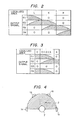
- Fig. 2 is an illustration of the relative voltage levels of the output signals 01,02,03 and 04 and the locations of the sonic image 2 in which the voltage levels are indicated by hatched area.
- the output signal O1 is shown to decrease from a maximum level to zero and the signal 02 is shewn to increase from zero to a maximum with the signals 03 and 04 being adjusted to zero when the sonic image 2 is moved from the leftmost point of the area L to the rightmost point.
- the sonic image 2 is moved from the leftmost point of the area K to its rightmost point.
- a decrease in output signal 03 and an increase in output signal 04 causes the image 2 to move from the leftmost point of the area R to its rightmost point.
- the signals applied to the side speakers lc and ld have equal voltage levels and in phase with each other, it is possible to localize the image 2 at a point exactly on the location of the listener 7 so that he is made to feel as if the sound is originated in his head.
- the.sonic image can be located at any point within a hatched area in Fig. 4.
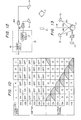
- Fig. 5 is an illustration of an alternative form of the panoramic potentiometer 3.
- This potentiometer includes switches 12a, 12b and 12c which selectively'connect the signal applied to the input terminal I into three signals for application to potentiometers 3a, 3b and 3c respectively.
- Each of the potentiometer arrangements 3a to 3c includes a pair of potentiometers connected together to the associated switch with the wiper tap points cf adjacent potentiometers being connected together to the cutput terminals 02 and 03 and the remaining tap points being connected to output terminals O1 and 04.
- Fig. 6 illustrates the switching conditions of the switches 12a to 12c and the relative voltage levels of the output signals Ol to 04 for effecting localization of sonic images in the areas L, K and R.
- Fig. 7 is an illustration of a second embodiment of the present invention in which two signals are applied to input terminals Il and I2. Each of these input signals carries no localization information.
- the system includes panoramic four-channel potentiometers 3d and 3e and adders 13a, 13b, 13c and 13d. Each of the four-channel panoramic potentiometers 3d and 3e is of the same construction as that shown in Fig. 1.
- the potentiometers 3d and 3e are connected to the input terminals Il and I2, respectively, to divide the received input signals into a set of four output signals on leads O1 to D4 and leads Ol' to O4', respectively.
- the signals on leads O1 and Ol' are combined in the adder 13a, the signals on leads 02 and 02' being combined in the adder 13b.
- the outputs of the adders 13a and 13b are applied to the recording system 5 or directly to amplifiers 6c and 6b and thence to speakers lc and la respectively to localize a sonic image 2a in the area L between these speakers.
- the signals on leads 03 and 03' are combined in the adder 13c, the signals 04 and 04' being combined in the adder 13d.
- the outputs of the adders 13c and 13d are applied to the recording system 5 or directly to amplifiers 6a and 6d respectively and thence to speakers lb and ld to effect localization of a sonic image 2b in the area R between these speakers.
- the sonic images'2a and 2b can be independently localized at any desized point by independently adjusting the panoramic potentiometers 3d and 3e within the frontal half plane of a radius from the center point of the listener 7 to any one of the speakers la to ld located at equal distances from the listener 7.
- the provision of a third panoramic potentiometer could also permit localization of an additional sonic image within the frontal half plane and permit movement.of each localized sonic image continuously by moving the joysticks of the associated panoramic potentiometers.
- Fig. I can be modified in a manner as illustrated in Fig. 8 which differs from the Fig. 1 embodiment in that the rear speakers le and lf are used instead of the front speakers la and lb. In this modified embodiment all the speakers are located symmetrically with respect to the listener 7. More specfically, the rear speakers are located at 150 degrees with respect to the normal N.
- a sonic image 2 is localized at any pcint within the area L' between speakers lc and le, the area K' between speakers le and lf and within the area R' between speakers If and ld.
- a movement of the joystick of the potentiometer 3 could also result in a continuous movement of the localized image within the rear half plane with respect to the listener 7 in a manner as described in connection with Fig. 1.
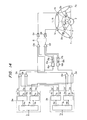
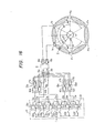
- Fig. 9 is an illustration of another 2embodiement of the invention in which the embodiments of Figs. 1 and 8 are combined to localize sonic images within an area of a full circle with the listener being located at the center.
- a voltage control device 14 comprises- a plurality of switches 12a to 12f connected in parallel with each other to the input terminal I and a plurality of 2-channel panoramic potentiometers 3a to 3f connected respectively the switches 12a to 12f.
- Each of the panoramic potentiometers includes two wiper terminals which are connected to the wiper terminals of adjacent panoramic potentiometers so that six.. output signals are delivered to leads 01 to 06 and thence to amplifiers 6a to 6f directly or via the recording system 5.
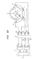
- Fig. 11 is an illustration of a further embodiment of the invention in which localization networks are used to generate phantom sound sources or speakers rather than by the use of actual speakers in addition to the front speakers la and lb:
- the embodiment of Fig. 11 differs from the Fig. 1 embodiment in that localization networks 15a and 15b are connected to the output terminals 01 and 04 of the 4-channel panoramic potentiometer 3.
- Each of the localization networks includes a first or common transfer circuit 16a (16b) and a second transfer circuit 17a (17b) which is connected to the output terminal of the common transfer circuit 16a (16b).
- Each localization network delivers a first output signal directly derived-.. from the output of the common transfer circuit 16 and a second output signal which is derived from the output of the second transfer circuit 17.
- An adder 13a combines the first output signals from the localization networks 15a and 15b and the output signal on terminal 03, and an adder 13b combines the second output signals from the localization networks 15a and 15b and the output signal on terminal 02.
- the combined outputs from the adders 13a and 13b are applied to amplifiers 6a and 6b, respectively, directly or via the recording system 5, and thence to front speakers la and lb.
- the details of the localization networks will now be explained with reference to Figs. 12 and 13.
- the outputs of the localization network '15 are assumed to be connected to front speakers la and lb via amplifiers 6a,6b.
- Fig. 12 the outputs of the localization network '15 are assumed to be connected to front speakers la and lb via amplifiers 6a,6b.
- Fig. 12 the outputs of the localization network '15 are assumed to be connected to front speakers la and lb via amplifiers 6a,6b.
- Fig. 12 the outputs of the local
- acoustic paths from the front left speaker la to the listener's left and right ears have different acoustic transfer functions represented by H 11 and H 12 , respectively, and acoustic paths from the front right speaker lb to the listener's left and right ears are designated by H12 and H 11' respectively.
- H ⁇ 1 and H ⁇ 2 designate the acoustic transfer functions between an actual sound source or speaker lc (located at right angles to the normal N to the listener 7) to the listener's right and left ears, respectively.
- the common transfer circuit 16 is designed to have the transfer function H ⁇ 1 /H 11 and the second transfer circuit 17 is designed to have the following transfer function:
- This phantom sound source F 1 is located exactly in the position of the actual speaker lc in the arrangement of Fig. 13. It is to be noted that by appropriately selecting the parameters of the transfer functions of the first and second transfer circuits 16 and 17 the phantom sound source may be located at any point around the listener 7. It is therefore possible to generate phantom sound sources F 1 and F2 in the arrangement of Fig. 11 at 90 degrees to the normal N to the listener 7 by appropriately selecting the parameters of the transfer circuits of the localization networks 15a and 15b. As described in connection with the embodiments of Fig. 1 sonic images can be located at any point in the front half plane defined by the actual speakers la and lb and phantom sound sources F 1 and F2.
- Fig. 14 illustrates a modified embodiment.of Fig. 11 in which two input signals are applied to terminals I 1 and I 2 in a manner similar to that shown in Fig. 7 with the exception that the localization networks 15a and 15b employed in the Fig. 11 embodiment are used to generate phantom sound sources in a two-speaker sound field.
- the adders 13a to 13d each combine the output signals of the four-channel panoramic potentiometers 3a and 3b in the same manner as in the Fig. 7 embodiment but differ therefrom in that they deliver their output signals to adders 13e and 13f from adders 13b and 13c, respectively, and to localization networks 15a and 15b from adders 13a and 13d and thence to the adders 13e and 13f.
- Sonic images 2a and 2b are individually located at any points within the front half plane by operating the potentiometers 3a and 3b. As previously decribed this embodiment also permits localization of any number of sonic images by the provision of a desired number of panoramic potentiometers.
- Localization networks can also permit localization behind the listener by arranging speakers at the rear of the listener as illustrated in Fig. 15.
- Localization networks may also be used to generate more than two phantom sound sources.
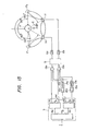
- An embodiment shown in Fig. 16 is intended to generate four phantom sound sources F 1 to F 4 .
- a voltage control device 14, as used in Fig. 9, receives a single channel signal at terminal I and delivers six output signals on leads 01 to 06.
- the signals on leads 02 and 03 are directly applied to adders 13a and 13b, respectively, the signals on leads 01 and 04 being applied to localization networks 15a and 15b, and the signals on leads 05 and 06 being applied to localization networks 15c and 15d respectively.
- the adder 13a combines the signal from lead 02 with outputs from localization networks 15a, 15b, 15c and 15d
- the adder 13b combines the signal from the lead 03 with output signals from the localization networks 15a to 15d.
- the outputs of the adders 13a and 13b are applied via amplifiers 6a and 6b and thence to front speakers lb and la, respectively.
- the localization networks 15a to 15d the phantom sound sources F l , F 2 , F 3 and F 4 are located symmetrically with respect to the listener 7 at 60-degree intervals.
- By manipulating the switches 12a to 12f and panoramic potentiometers 3a to 3f it is possible to localize sonic images at any point within the area of a full circle.
- Fig. 17 is a graphic illustration of psycho-acoustical verification tests for the purpose of verifying the localization of sonic images creatd by actual and phantom sound sources which are located at 30 and 90 degrees to the normal to a listener. The tests involved 10 subjects who were seated in the respective sound fields to record the direction in which they perceived that the sound is coming. In Fig. 17 the ratio of the signal level of one of the sound sources to that of the other is indicated on the abscissa and the angular position of the localized image is indicated on the ordinate.
- a solid-line curve S 1 is a plot of averaged values of angular orientations recorded with the actual speaker system and a broken-line curve 8 2 is a plot of the corresponding data obtained from the phantom speaker system. Curves S 1 and S 2 verify that the sound is made to appear tooriginate from the intended angular positions.
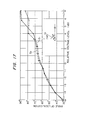
- Fig. 18 illustrates other verification tests in which the subjects were seated in an actual and a phantom sound field in each of which sound sources are located at three positions, one at 30 degrees to the normal to the listener and the other suces being at +90 degrees to the normal.
- the ratio of the signal applied to the front speaker to those applied to other speakers On the ordinate is indicated the relative distance to the localized sonic image which the subjects perceived at a given signal ratio.
- a solid-line curve S 3 is a plot obtained from the actual sound field and a broken-line curve S 4 is a plot obtained from the phantom sound field in which only the front source is an actual sound source. Both curves verify that the distance to the localixed images is clearly perceived by the listeners in respect of both phantom and actual sound fields.
- the panoramic potentiometer is designed to establish voltage levels of the output signals in a predetermined variable ratio as a function of movement of the joystick, it is impossible to vary the distance from one localized sonic image to the listener in relation to the distance from another localized sonic image to the listener regardless of the ratio established by the panoramic potentiometer. This is accomplished by the provision of one or more attenuators in the input circuits of one or more speakers but smaller in number than the total number of the speakers.
- Figs. 7,8,9,14,15 and 16 are modified as shown in Figs. 21 to 26, respectively.
- attenuators 18a and 18b are connected between the outputs of adders 13c, 13b and the inputs of the amplifiers 6a, 6b, respectively, to localize a sonic image 2a at a particular distance D from the listener within the radius A (between the center of listener 7 .and the speakers la to lc) in relation to the distance from another sonic image 2b to the listener.
- One of the attenuators l8a.and 18b can be dispensed with.
- the attenuators 18a and 18b are connected in the input circuits of the amplifiers 6c and 6d to modify the levels of the signals to the rear speaker le and to the right side speaker ld. whereby the sonic image 2 can be located a distance D from the listener independently of the adjustment of the panoramic potentiometer 3.
- attenuators 18a, 18b, 18c and 18d are connected in the input circuits to the amplifiers 6b, 6c, 6e and 6f, respectively to alter the levels of signals applied to the front speakers la and lb and the levels of signals applied to the rear speakers le and lf in relation to the levels of signals applied to side speakers lc and ld.
- Fig. 24 which is a modification of the Fig. 14 embodiment, attenuator 18a is connected between the output of adder 13c and an input of the adder 13e, and attenuator 13b is connected in the circuit between the adders 13b and 13f.
- Fig. 25 which is a modification of the Fig. 15 embodiment, attenuator 18a is connected in the circuit between potentiometer 4c and adder 13a and attenuator 13b is connected in the circuit between potentiometer 4e and adder 13b.
- Fig. 16 which is a modification of the Fig.
- Attenuator 18a is connected in the circuit between the common output of potentiometers 3a,3b and adder 13a and attenuator 18b is connected in the circuit between the common output of potentiometers 3b,3c and adder 13b.
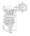
- the sound reproducing system of the present invention is further modified as shown in Fig. 27 which produces reverberation in the sound field to enhance the realism of the original sound field.
- the system of Fig. 27 comprises a level adjusting device or two-channel panoramic potentiometer 11 which divides an input signal applied to terminal I into two- level-proportioned output signals one of which is applied to a localization network 150 of the construction identical to those described in the previous embodiments and the other of which is applied to a reverberation generator 23.
- the reverberation generator circuit 23 comprises a level adjusting device 24, a delay circuit 25 and a reverberation generator 26 all of which are connected in a series circuit which in turn is connected to the outputs of a plurality of primary echo generators 27a to 27m, or an m-channel echo generator.
- Each of the primary echo generators comprises a level adjusting device 28 and a delay circuit 29 connected in a series circuit the input of. which is connected to the input of the reverberation generator circuit 23 in common with other primary echo generators and the output of which is connected individually to a respective one of a plurality of 6-channel panoramic potentiometers 3a to 3m.
- An adder stage 30 is provided to combine the corresponding outputs of the panoramic potentiometers 3a to 3m to derive 6 output signals 01 to 06.
- the signals 02 and 03 are coupled respectively to adders 31a and 31b, while the signals 01,04,05 and 06 are coupled to localization networks 15a, 15b, 15c and 15d, respectively.
- the first localizing output of each network 15 is applied to the adder 31a and the second localizing signal of each network is applied to the adder 31b.
- the localization networks 15a and 15b are designed so that phantom sound sources are generated at +90 degrees to the normal to the listener, while the localization networks 15c and 15d are designed so that phantom sound sources are generated at +150 degrees to the normal.
- a combined output signal Ol' from the adder 31a is applied to an adder 32a which combines it with a first localizing signal Xl from the localization network 150.
- a combined signal 02' from the adder 31b is applied to an adder 32b where it is combined with a second localizing signal X2 from the localization network 150.
- the outputs of the adders 32a and 32b are applied directly to amplifiers 6a and 6b respectively (or via a recording system 5) and thence to front left speaker la and front right speaker lb to generate a reproduction sound field in which phantom sound sources Fl and F2 are generated at +90 degrees to the normal to the listener 7 and phantom sound sources F3 and F4 are generated at + 150 degrees to the normal.
- the input signal applied to the terminal I is a signal which is directly received by a microphone in contrast with an indirect signal which is received by the microphone by the reflection of the direct signal from the.surrounding walls.
- the signals applied to the speakers la and lb contains the direct and indirect components of the input signal.
- the indirect components of the signals applied to the speakers are generated by the reverberation generator circuit 23 whose amplitude relative to the direct component is adjusted by the level adjusting device 24 and whose time of occurrence relative to the time of.occurrence of the direct component in the sound reproduction field is determined by the delay circuit 25.
- a typical value of the delay time introduced by the delay circuit 25 is 50 milliseconds.
- the indirect components of the signal further include primary echo signals generatd by the echo generators 27a to 27m.
- the amplitude of each echo"signal relative to other echo signals is adjusted by the level adjusting device 28 and the time of occurrence of each echo relative to the direct component is determined by the delay circuit 29.
- Fig. 28 illustrates the relative amplitude of the direct and indirect components of the input signal and their times of occurrence in the sound field in which numerals 19, 20 and 21 respectively indicate the direct signal, primary echo signals and the reverberation.
- the delay times introduced by the delay circuits 29a to 29m range from 10 to 50 milliseconds.
- the listener 7 hears localized direct component and localized echos and reverberations so that he has the impression that such primary echos come from various sources with the reverberating sounds coming in all directions from the distance.
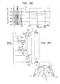
- Fig. 27 can be modified as shown in Fig. 29 in which the output of the reverberation generator circuit 23 is branched into two component one of which is directly applied to the input of the 90-degree localization network 15a and the other of which is applied through a delay circuit or phase inverter 35 to the input of the -90-degree localization network 15b. Therefore, reverberations are made to appear to originate from the phantom sources Fl and F2.
- This embodiment serves to give the sense of an expanded field of reverberating sounds.
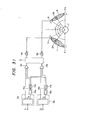
- Figs. 27 and 29 can be modified to localize the indirect signals at +90 degrees to the normal to the listener 7 as illustrated in Fig. 30 by eliminating the 150-degree localization networks 15c and 15d from the previous embodiments, whereby the listener 7 hears indirect sounds as if they are coming from sources located in the front half plane.
- the present invention can be further modified to give the impression of an expanded stage width by the use of the localization networks as previously described by making them process stereophonic signals, the signals carrying localization information.
- 2-channel stereophonic signals are applied respectively to input terminals Il and I2 and thence to 2-channel panoramic potentiometers 3a and 3b, respectively.
- One of the outputs of the potentiometer 3a is coupled to adder 13a and the other output is coupled to +90-degree localization network 15a where the signal is processed to derive two localized signals, one of which is applied to the adder 13a and the other of which is applied to adder 13b.
- one of the outputs of the potentiometer 3b is applied to the adder 13b and the other output is applied to a -90-degree localization network 15b.
- One of the localized outputs of the network 15b is applied to the adder 13b and the other output is applied to the adder 13a.
- the outputs of the aders 13a, 13b are fed to amplifiers 6a and 6b, directly or via recording system 6, and thence to front speakers la and lb.
- sonic images 2a and 2b are localized respectively at any point in area L between speaker la and phantom source Fl and in area R between speaker lb and phantom source F2.
- the joysticks of the potentiometers 3a and 3b By moving the joysticks of the potentiometers 3a and 3b continuously, the localized images are moved continuously within the areas L and R.
- Fig. 32 is an illustration of an example of such applications.
- the sound system shown in Fig. 32 is similar to the embodiment.of Fig. 7 with the exception that the panoramic potentiometers 3a and 3b receive synthesized musical signals from an electronic musical sound-source including a keyboard or switching circuit 32 which applies a selected one of signals supplied from an external synthesizer of a known construction to a sound converter 34 of the conventional design which modifies the waveform of the input signal into the musical note of a desired musical instrument.
- the sonic images of the synthesized sound can be continually moved within the areas between speakers la, lb, lc and-ld.
Abstract
Description
- The present invention relates generally to sound reproducing systems, and in particular to a system for localizing sonic images in desired areas using two loudspeakers located in front of a listener.
- In conventional multi-channel sound reproduction systems sonic images appear to originate in the area between two loudspeakers located in front of the listener. In stereophonic systems in which the signals carries information as to the direction and distance of sounds or sonic images with respect to the listener, the sonic images are localized so that they are made to appear to originate from a point determined by the information carried by the input stereophonic signals. Monophonic signals which carries no localization information can also be localized when applied to two loudspeakers at a desired position by varying the relative amplitude of the signals applied to the speakers to the other. However, the localized images are restricted to the area between the two speakers so that the listener hears sounds at the same distance, that is, the distance between the speakers and the listener. It is therefore desirable to localize sound at any point around the listener and to make the localized image move continuously in the sound reproduction field in response to a manual control regardless of whether the input audio signal is stereophonic or monophonic.
- The present invention permits localization of sonic images whose angular position and distance to the listener is made variable by manually controlling the relative voltage levels of each channel signal to other channel signals. The invention contemplates to localize at least one sound source, either real or phantom, at 90 degrees to the normal to the listener in a sound reproducing field in which two loudspeakers are located in front of the listener. The localized real or phantom sound source and the front speakers are located symmetrically with respect to the listener.
- In accordance with the invention, an input audio signal is divided into a plurality of channel signals which are applied respectively to a plurality of voltage adjusting elements, which is preferably a panoramic potentiometer. Two of the channel signals are applied respectively to the loudspeakers and-the remainder is .applied to an additional loudspeaker to generate the real sound source, or combined with the channel signals applied to the front speakers to generate the phantom sound source. By manually controlling the voltage adjusting elements, a sonic image is located in an area between the real or phantom sound source and one of the front loudspeakers as well as in the area between the front speakers. Preferably, two real or phantom sound sources are generated on both sides of the listener symmetrically with respect to the listener. If the signals used to generate such additional sound sources are of equal amplitude and in phase with each other, the variation of the channel signals applied to the front speakers in relation to the other channel signals , permits the sonic image to be localized at a point away from the front speakers toward the listener, so that it is localized at any point within the front half plane of the listener. If additional ones of such real or phantom sources are located at the rear of the listener, it is possible to localize sonic images within the area of a full circle.
- The realism of the original sound field can be enhanced by generating primary echo signals which are the reflections of a direct signal from the surrounding walls and by additionally generating reverberation. signals. These indirect signals are generated at specified delay times and applied at relatively different voltage levels to localization networks, and combined with the direct signal and applied to the front loudspeakers. The system of the invention thus enables the listener to have the impression of an expanded stage width if the system is supplied with stereophonic signals.
- These and other features and advantages of the invention will become apparent from the following description with reference to the accompanying drawings in which:
- Fig. 1 is an illustration of a first embodiment of the present invention;
- Figs. 2 and 3 are representations of the location of localized sonic image as'a function of the relative voltage levels of the channel signals useful for describing the operation of the embodiment of Fig. 1;
- Fig. 4 is a sketch illustrating the area in which sonic images can be-localized;
- Fig. 5 is an illustration of an alternative form of the voltage adjusting device of Fig. 1;
- Fig. 6 is a representation of the location of localized sonic image as a function of the relative voltage levels of the channel signals and the operating states of the switches of Fig. 5;
- Fig. 7 is an illustration of a first modified form of the embodiment of Fig. 1
- Fig. 8 is an illustration of a second modified form of the embodiment of Fig. 1;
- Fig. 9 is an illustration of a third modified form of,the embodiment of Fig. 1;
- Fig. 10 is a representation of the location of sonic image localized by the embodiment of Fig. 9 as a function of the operating states of switches and the relative voltage levels of channel signals;
- Fig. 11 is an illustration of a second embodiment of the present invention;
- Figs. 12 and 13 are sketches useful for describing the transfer functions of the localization betworks of Fig. 11;
- Fig. 14 is an illustration of a first modified form of the embodiment of Fig. 11;
- Fig. 15 is an illustration of a second modified form of the embodiment of Fig. 11;
- Fig. 16 is an illustration of a third modified form of the embodiment of Fig. 11;
- Figs. 17 to 20 are illustrations of the results of psycho-acoustical verification tests conducted on the systems of the invention;
- Figs. 21, 22, 23, 24, 25 and 26 are illustrations of modified forms of the embodiments of Figs. 7, 8, 9, 14, 15 and 16, respectively;
- Fig. 27 is an illustration of a third embodiment of the invention in which primary echos and reverberations are generated in the sound field in addition to the direct signal;
- Fig. 28 is a graphic illustration of echos and reverberations which are generated by the system of Fig. 27 at relatively delayed times in response to a direct signal;
- Figs. 29 and 30 are illustrations of modified forms of the embodiment of Fig. 27; .
- Fig. 31 is an illustration of a fourth embodiment of the invention which enables stereophonic signals to be localized in an expanded stage width; and
- Fig. 32 is an illustration of a fifth embodiment of the invention in which signals from an electronic sound synthesizer are localized in a reproducing sound field.
- Referring now to Fig. 1 of the drawings, a first embodiment of the present invention is illustrated as comprising a
panoramic potentiometer 3, a plurality oflinear amplifiers 6a to 6d, and loudspeakers la,lb,lc and ld connected respectively to the outputs of theamplifiers panoramic potentiometer 3 comprises a pair ofpotentiometers potentiometer 3 further includespotentiometers potentiometers potentiometer 4a to divide the voltage developed thereat further into two output signals which appear at the wiper tap points of thepotentiometers potentiometers potentiometers potentiometer 4b to divide the voltage developed thereat further into two output signals which appear atoutput terminals panoramic potentiometer 3 includes a common joystick, not shown, which when manually operated causes a respective one cf the wiper tap points of theinternal potentiometers 4a to 4f to mcve across the associated resistance elements so that the voltage at one output terminal is varied in relation to the other output voltages. The signal applied to the input terminal I carries no information as to the localization of sonic images and such signals are available from a monaural signal source or one of the channels of a multi-channel stereophony. The voltage signals atoutput terminals 01 to 04 may be recorded into separate tracks of a recording medium of arecording system 5 rather than directly applied to theamplifiers 6a to 6d. The signal amplified atamplifiers listener 7 and the speakers lc and ld are located at equal distances from thelistener 7 at angular positions which are 90 degrees to the normal N to thelistener 7. Preferably, the side speakers lc and 1d are located at the same distances as the speakers la and lb are located with respect to thelistener 7. By operating the ccmmon joystick of thepanoramic potentiometer 3 it is possible to localize a sonic image in an area between any two of the speakers la to ld, so that the sonic image as indicated at 2 can be moved from an area L (between speakers la and lc) to an area K (between speakers la and lb) and thence to an area R (between speakers lb and 1d). Fig. 2 is an illustration of the relative voltage levels of theoutput signals sonic image 2 in which the voltage levels are indicated by hatched area. In this Table the output signal O1 is shown to decrease from a maximum level to zero and thesignal 02 is shewn to increase from zero to a maximum with thesignals sonic image 2 is moved from the leftmost point of the area L to the rightmost point. By decreasing the level ofsignal 02 while increasing thesignal 03 with thesignals sonic image 2 is moved from the leftmost point of the area K to its rightmost point. Likewise, with thesignals output signal 03 and an increase inoutput signal 04 causes theimage 2 to move from the leftmost point of the area R to its rightmost point. - In this embodiment, if the signals applied to the side speakers lc and ld have equal voltage levels and in phase with each other, it is possible to localize the
image 2 at a point exactly on the location of thelistener 7 so that he is made to feel as if the sound is originated in his head. With the voltage levels of thesignals listener 7 the impression of sound originating from within his head, it is possible to locate theimage 2 at a point intermediate the speaker la and thelistener 7 by appropriately adjusting the level of the signal applied to the speaker la.in relation to the level of the signals applied to the speakers lc and ld, so that thepanoramic potentiometer 3 permits thesonic image 2 to move continuously from the speaker la to thelistener 7 or from the latter to the former. Fig. 3 illustrates the relative voltage levels of theoutput signals 01 to 04 to permit localization of sound images between the speaker la and thelistener 7 in which numeral A represents the distance between them and D represents the distance between theimage 2 and thelistener 7. It is, of course, possible to localize theimage 2 at a point other than between the speaker la and the listener. For example, a variation of the voltage levels of the signals applied to speakers la and lb relative to each other so that theimage 2 is located between the speakers la and lb will permit such sonic image to be relocated to any point closer to thelistener 7 by readjusting the levels of thesignals - Fig. 5 is an illustration of an alternative form of the
panoramic potentiometer 3. This potentiometer includesswitches potentiometers potentiometer arrangements 3a to 3c includes a pair of potentiometers connected together to the associated switch with the wiper tap points cf adjacent potentiometers being connected together to thecutput terminals switches 12a to 12c and the relative voltage levels of the output signals Ol to 04 for effecting localization of sonic images in the areas L, K and R. - Fig. 7 is an illustration of a second embodiment of the present invention in which two signals are applied to input terminals Il and I2. Each of these input signals carries no localization information. The system includes panoramic four-
channel potentiometers adders panoramic potentiometers potentiometers adder 13a, the signals onleads 02 and 02' being combined in theadder 13b. The outputs of theadders recording system 5 or directly toamplifiers sonic image 2a in the area L between these speakers. On the other hand, the signals onleads 03 and 03' are combined in theadder 13c, thesignals 04 and 04' being combined in theadder 13d. The outputs of theadders recording system 5 or directly toamplifiers sonic image 2b in the area R between these speakers. As described in the previous embodiment, the sonic images'2a and 2b can be independently localized at any desized point by independently adjusting thepanoramic potentiometers listener 7 to any one of the speakers la to ld located at equal distances from thelistener 7. The provision of a third panoramic potentiometer could also permit localization of an additional sonic image within the frontal half plane and permit movement.of each localized sonic image continuously by moving the joysticks of the associated panoramic potentiometers. - The embodiment of Fig. I can be modified in a manner as illustrated in Fig. 8 which differs from the Fig. 1 embodiment in that the rear speakers le and lf are used instead of the front speakers la and lb. In this modified embodiment all the speakers are located symmetrically with respect to the
listener 7. More specfically, the rear speakers are located at 150 degrees with respect to the normal N. Asonic image 2 is localized at any pcint within the area L' between speakers lc and le, the area K' between speakers le and lf and within the area R' between speakers If and ld. A movement of the joystick of thepotentiometer 3 could also result in a continuous movement of the localized image within the rear half plane with respect to thelistener 7 in a manner as described in connection with Fig. 1. - Fig. 9 is an illustration of another 2embodiement of the invention in which the embodiments of Figs. 1 and 8 are combined to localize sonic images within an area of a full circle with the listener being located at the center. In this embodiment, a
voltage control device 14 comprises- a plurality ofswitches 12a to 12f connected in parallel with each other to the input terminal I and a plurality of 2-channelpanoramic potentiometers 3a to 3f connected respectively theswitches 12a to 12f. Each of the panoramic potentiometers includes two wiper terminals which are connected to the wiper terminals of adjacent panoramic potentiometers so that six.. output signals are delivered toleads 01 to 06 and thence toamplifiers 6a to 6f directly or via therecording system 5. There is a total of six speakers la to lf, the speakers la and lb being located in front of thelistener 7 and the speakers le and lf being at the rear and the speakers lc and ld being located sideways. All the speakers are arranged in a symmetrical relationship with respect to the listener. By operating theswitches 12a to 12f andpanoramic potentiometers 3a to 3f, sonic images can be localized within the hatched area. If the the signals applied to the speakers lc and ld are of equal amplitude and in phase with each other, the sonic images can be located at any point in the circle including the areas L, K, R, L', K' and R'. The operating stutus of theswitches 12a to 12f and the relative levels of the output signals are illustrated in Fig. 10 to effect localization within the hatched areas L, K. R, R',K' and L'. - Fig. 11 is an illustration of a further embodiment of the invention in which localization networks are used to generate phantom sound sources or speakers rather than by the use of actual speakers in addition to the front speakers la and lb: The embodiment of Fig. 11 differs from the Fig. 1 embodiment in that
localization networks output terminals panoramic potentiometer 3. Each of the localization networks includes a first orcommon transfer circuit 16a (16b) and asecond transfer circuit 17a (17b) which is connected to the output terminal of thecommon transfer circuit 16a (16b). Each localization network delivers a first output signal directly derived-.. from the output of thecommon transfer circuit 16 and a second output signal which is derived from the output of thesecond transfer circuit 17. Anadder 13a combines the first output signals from thelocalization networks terminal 03, and anadder 13b combines the second output signals from thelocalization networks terminal 02. The combined outputs from theadders amplifiers recording system 5, and thence to front speakers la and lb. The details of the localization networks will now be explained with reference to Figs. 12 and 13. In Fig. 12 the outputs of the localization network '15 are assumed to be connected to front speakers la and lb viaamplifiers listener 7 would have the impression that the sound is coming from the speaker lc rather than from the front speakers la and lb. To create a phantom sound source F1 in the two-speaker system of Fig. 12 thecommon transfer circuit 16 is designed to have the transfer function Hφ1/H11 and thesecond transfer circuit 17 is designed to have the following transfer function:
- This phantom sound source F1 is located exactly in the position of the actual speaker lc in the arrangement of Fig. 13. It is to be noted that by appropriately selecting the parameters of the transfer functions of the first and
second transfer circuits listener 7. It is therefore possible to generate phantom sound sources F1 and F2 in the arrangement of Fig. 11 at 90 degrees to the normal N to thelistener 7 by appropriately selecting the parameters of the transfer circuits of thelocalization networks - Fig. 14 illustrates a modified embodiment.of Fig. 11 in which two input signals are applied to terminals I1 and I2 in a manner similar to that shown in Fig. 7 with the exception that the
localization networks adders 13a to 13d each combine the output signals of the four-channelpanoramic potentiometers adders adders localization networks adders adders adders amplifiers Sonic images potentiometers - Localization networks can also permit localization behind the listener by arranging speakers at the rear of the listener as illustrated in Fig. 15.
- Localization networks may also be used to generate more than two phantom sound sources. An embodiment shown in Fig. 16 is intended to generate four phantom sound sources F1 to F4. A
voltage control device 14, as used in Fig. 9, receives a single channel signal at terminal I and delivers six output signals onleads 01 to 06. The signals onleads adders leads localization networks leads localization networks adder 13a combines the signal fromlead 02 with outputs fromlocalization networks adder 13b combines the signal from thelead 03 with output signals from thelocalization networks 15a to 15d. The outputs of theadders amplifiers localization networks 15a to 15d the phantom sound sources Fl, F2, F3 and F4 are located symmetrically with respect to thelistener 7 at 60-degree intervals. By manipulating theswitches 12a to 12f andpanoramic potentiometers 3a to 3f it is possible to localize sonic images at any point within the area of a full circle. - Fig. 17 is a graphic illustration of psycho-acoustical verification tests for the purpose of verifying the localization of sonic images creatd by actual and phantom sound sources which are located at 30 and 90 degrees to the normal to a listener. The tests involved 10 subjects who were seated in the respective sound fields to record the direction in which they perceived that the sound is coming. In Fig. 17 the ratio of the signal level of one of the sound sources to that of the other is indicated on the abscissa and the angular position of the localized image is indicated on the ordinate. A solid-line curve S1 is a plot of averaged values of angular orientations recorded with the actual speaker system and a broken-
line curve 82 is a plot of the corresponding data obtained from the phantom speaker system. Curves S1 and S2 verify that the sound is made to appear tooriginate from the intended angular positions. - Fig. 18 illustrates other verification tests in which the subjects were seated in an actual and a phantom sound field in each of which sound sources are located at three positions, one at 30 degrees to the normal to the listener and the other suces being at +90 degrees to the normal. On the abscissa is indicated the ratio of the signal applied to the front speaker to those applied to other speakers and on the ordinate is indicated the relative distance to the localized sonic image which the subjects perceived at a given signal ratio. A solid-line curve S3 is a plot obtained from the actual sound field and a broken-line curve S4 is a plot obtained from the phantom sound field in which only the front source is an actual sound source. Both curves verify that the distance to the localixed images is clearly perceived by the listeners in respect of both phantom and actual sound fields.
- Verification tests were further conducted with respect to a speaker arrangement in which sound sources are located in two positions, one.at 90 degrees to the normal to the listener and the other at 150 degrees to the normal. In Fig. 19 curves S5 and S6 are plots obtained respectively from actual and phantom sound fields in each of which sound sources are located in 90- and 150-degree positions with respect to the normal. IN Fig. 20, curves 57 and S8 are plots obtained respectively from actual and phantom sound fields in each of which sound sources are locatred at the reat of the listener (+150 degrees to the normal). These tests verify that the system of the invention is capable of providing localization of sound images in clearly distinguishable angular orientations.
- Since the panoramic potentiometer is designed to establish voltage levels of the output signals in a predetermined variable ratio as a function of movement of the joystick, it is impossible to vary the distance from one localized sonic image to the listener in relation to the distance from another localized sonic image to the listener regardless of the ratio established by the panoramic potentiometer. This is accomplished by the provision of one or more attenuators in the input circuits of one or more speakers but smaller in number than the total number of the speakers.
- To this end, the embodiments of Figs. 7,8,9,14,15 and 16 are modified as shown in Figs. 21 to 26, respectively. In Fig. 21,
attenuators adders amplifiers sonic image 2a at a particular distance D from the listener within the radius A (between the center oflistener 7 .and the speakers la to lc) in relation to the distance from anothersonic image 2b to the listener. One of the attenuators l8a.and 18b can be dispensed with. In Fig. 22, theattenuators amplifiers sonic image 2 can be located a distance D from the listener independently of the adjustment of thepanoramic potentiometer 3. In the system of Fig. 23, which is a modification of the Fig. 9 embodiment,attenuators amplifiers attenuator 18a is connected between the output ofadder 13c and an input of theadder 13e, andattenuator 13b is connected in the circuit between theadders attenuator 18a is connected in the circuit betweenpotentiometer 4c andadder 13a andattenuator 13b is connected in the circuit betweenpotentiometer 4e andadder 13b. In Fig. 16, which is a modification of the Fig. 16 embodiment,attenuator 18a is connected in the circuit between the common output ofpotentiometers adder 13a andattenuator 18b is connected in the circuit between the common output ofpotentiometers adder 13b. - The sound reproducing system of the present invention is further modified as shown in Fig. 27 which produces reverberation in the sound field to enhance the realism of the original sound field. The system of Fig. 27 comprises a level adjusting device or two-channel panoramic potentiometer 11 which divides an input signal applied to terminal I into two- level-proportioned output signals one of which is applied to a
localization network 150 of the construction identical to those described in the previous embodiments and the other of which is applied to areverberation generator 23. Thereverberation generator circuit 23 comprises alevel adjusting device 24, adelay circuit 25 and areverberation generator 26 all of which are connected in a series circuit which in turn is connected to the outputs of a plurality ofprimary echo generators 27a to 27m, or an m-channel echo generator. Each of the primary echo generators comprises a level adjusting device 28 and a delay circuit 29 connected in a series circuit the input of. which is connected to the input of thereverberation generator circuit 23 in common with other primary echo generators and the output of which is connected individually to a respective one of a plurality of 6-channelpanoramic potentiometers 3a to 3m. Anadder stage 30 is provided to combine the corresponding outputs of thepanoramic potentiometers 3a to 3m to derive 6 output signals 01 to 06. Thesignals adders 31a and 31b, while thesignals localization networks network 15 is applied to the adder 31a and the second localizing signal of each network is applied to theadder 31b. Thelocalization networks localization networks - A combined output signal Ol' from the adder 31a is applied to an
adder 32a which combines it with a first localizing signal Xl from thelocalization network 150. A combined signal 02' from theadder 31b is applied to anadder 32b where it is combined with a second localizing signal X2 from thelocalization network 150. The outputs of theadders amplifiers listener 7 and phantom sound sources F3 and F4 are generated at +150 degrees to the normal. - The input signal applied to the terminal I is a signal which is directly received by a microphone in contrast with an indirect signal which is received by the microphone by the reflection of the direct signal from the.surrounding walls. By application of such direct signal to the input terminal of the system, the signals applied to the speakers la and lb contains the direct and indirect components of the input signal. The indirect components of the signals applied to the speakers are generated by the
reverberation generator circuit 23 whose amplitude relative to the direct component is adjusted by thelevel adjusting device 24 and whose time of occurrence relative to the time of.occurrence of the direct component in the sound reproduction field is determined by thedelay circuit 25. A typical value of the delay time introduced by thedelay circuit 25 is 50 milliseconds. - The indirect components of the signal further include primary echo signals generatd by the
echo generators 27a to 27m. The amplitude of each echo"signal relative to other echo signals is adjusted by the level adjusting device 28 and the time of occurrence of each echo relative to the direct component is determined by the delay circuit 29. Fig. 28 illustrates the relative amplitude of the direct and indirect components of the input signal and their times of occurrence in the sound field in which numerals 19, 20 and 21 respectively indicate the direct signal, primary echo signals and the reverberation. As illustrated in Fig. 28, the delay times introduced by thedelay circuits 29a to 29m range from 10 to 50 milliseconds. Since the indirect components are passed through thelocalization networks 15a to 15d-and combined with the localized direct signals in theadders listener 7 hears localized direct component and localized echos and reverberations so that he has the impression that such primary echos come from various sources with the reverberating sounds coming in all directions from the distance. - The embodiment of Fig. 27 can be modified as shown in Fig. 29 in which the output of the
reverberation generator circuit 23 is branched into two component one of which is directly applied to the input of the 90-degree localization network 15a and the other of which is applied through a delay circuit orphase inverter 35 to the input of the -90-degree localization network 15b. Therefore, reverberations are made to appear to originate from the phantom sources Fl and F2. This embodiment serves to give the sense of an expanded field of reverberating sounds. - The embodiments of Figs. 27 and 29 can be modified to localize the indirect signals at +90 degrees to the normal to the
listener 7 as illustrated in Fig. 30 by eliminating the 150-degree localization networks listener 7 hears indirect sounds as if they are coming from sources located in the front half plane. - The present invention can be further modified to give the impression of an expanded stage width by the use of the localization networks as previously described by making them process stereophonic signals, the signals carrying localization information. This is accomplished by an embodiment shown in Fig. 31. In this embodiment, 2-channel stereophonic signals are applied respectively to input terminals Il and I2 and thence to 2-channel
panoramic potentiometers potentiometer 3a is coupled to adder 13a and the other output is coupled to +90-degree localization network 15a where the signal is processed to derive two localized signals, one of which is applied to theadder 13a and the other of which is applied toadder 13b. Similarly, one of the outputs of thepotentiometer 3b is applied to theadder 13b and the other output is applied to a -90-degree localization network 15b. One of the localized outputs of thenetwork 15b is applied to theadder 13b and the other output is applied to theadder 13a. The outputs of theaders amplifiers recording system 6, and thence to front speakers la and lb. By operating the 2-channelpanoramic potentiometers sonic images potentiometers - The system of the present invention can be combined with an electronic musical instrument to localize sonic images of synthesized sound. Fig. 32 is an illustration of an example of such applications. The sound system shown in Fig. 32 is similar to the embodiment.of Fig. 7 with the exception that the
panoramic potentiometers sound converter 34 of the conventional design which modifies the waveform of the input signal into the musical note of a desired musical instrument. By continual movement of the joysticks of thepotentiometers
Claims (26)
Applications Claiming Priority (10)
| Application Number | Priority Date | Filing Date | Title |
|---|---|---|---|
| JP35261/80 | 1980-03-19 | ||
| JP3526180A JPS56132100A (en) | 1980-03-19 | 1980-03-19 | Acoustic image orientating device |
| JP83619/80 | 1980-06-19 | ||
| JP8361980A JPS579200A (en) | 1980-06-19 | 1980-06-19 | Controller for feeling of sound image interval |
| JP99237/80 | 1980-07-18 | ||
| JP9923780A JPS5724200A (en) | 1980-07-18 | 1980-07-18 | Indirect-sound generating circuit |
| JP13653080U JPS5760499U (en) | 1980-09-24 | 1980-09-24 | |
| JP136530/80U | 1980-09-24 | ||
| JP55140324A JPS5764000A (en) | 1980-10-06 | 1980-10-06 | Controller for distance feeling of sound image |
| JP140324/80 | 1980-10-06 |
Publications (3)
| Publication Number | Publication Date |
|---|---|
| EP0036337A2 true EP0036337A2 (en) | 1981-09-23 |
| EP0036337A3 EP0036337A3 (en) | 1981-10-21 |
| EP0036337B1 EP0036337B1 (en) | 1985-02-20 |
Family
ID=27521683
Family Applications (1)
| Application Number | Title | Priority Date | Filing Date |
|---|---|---|---|
| EP81301165A Expired EP0036337B1 (en) | 1980-03-19 | 1981-03-18 | Sound reproducing system having sonic image localization networks |
Country Status (3)
| Country | Link |
|---|---|
| US (1) | US4524451A (en) |
| EP (1) | EP0036337B1 (en) |
| DE (1) | DE3168990D1 (en) |
Cited By (10)
| Publication number | Priority date | Publication date | Assignee | Title |
|---|---|---|---|---|
| EP0100153A2 (en) * | 1982-07-23 | 1984-02-08 | Stereo Concepts, Inc. | Apparatus and method for enhanced psychoacoustic imagery |
| WO1985001177A1 (en) * | 1983-09-07 | 1985-03-14 | Polyak Gabor | Method of and apparatus for realising spatial sound effects |
| EP0142213A1 (en) * | 1983-11-17 | 1985-05-22 | Koninklijke Philips Electronics N.V. | Apparatus for generating a pseudo-stereo signal |
| GB2148672A (en) * | 1983-09-22 | 1985-05-30 | Casio Computer Co Ltd | Pan-pot control apparatus |
| EP0209380A2 (en) | 1985-07-17 | 1987-01-21 | Sony Corporation | Recording and/or reproducing apparatus |
| EP0499729A1 (en) * | 1989-12-07 | 1992-08-26 | Qsound Limited | Sound imaging apparatus for a video game system |
| WO1994027416A1 (en) * | 1993-05-11 | 1994-11-24 | One Inc. | Stereophonic reproduction method and apparatus |
| EP0706745A4 (en) * | 1992-11-02 | 1995-11-20 | 3Do Co | Method for generating three-dimensional sound |
| WO1998020706A1 (en) * | 1996-11-07 | 1998-05-14 | Deutsche Thomson-Brandt Gmbh | Method and device for projecting sound sources onto loudspeakers |
| CN111213202A (en) * | 2017-10-20 | 2020-05-29 | 索尼公司 | Signal processing device and method, and program |
Families Citing this family (30)
| Publication number | Priority date | Publication date | Assignee | Title |
|---|---|---|---|---|
| JPS60107998A (en) * | 1983-11-16 | 1985-06-13 | Nissan Motor Co Ltd | Acoustic device for automobile |
| US4569074A (en) * | 1984-06-01 | 1986-02-04 | Polk Audio, Inc. | Method and apparatus for reproducing sound having a realistic ambient field and acoustic image |
| US5005201A (en) * | 1989-02-14 | 1991-04-02 | Rca Licensing Corporation | Apparatus and method thereof for improvement of stereophonic sound |
| WO1992009921A1 (en) * | 1990-11-30 | 1992-06-11 | Vpl Research, Inc. | Improved method and apparatus for creating sounds in a virtual world |
| US5684881A (en) * | 1994-05-23 | 1997-11-04 | Matsushita Electric Industrial Co., Ltd. | Sound field and sound image control apparatus and method |
| GB2295072B (en) * | 1994-11-08 | 1999-07-21 | Solid State Logic Ltd | Audio signal processing |
| US5850455A (en) * | 1996-06-18 | 1998-12-15 | Extreme Audio Reality, Inc. | Discrete dynamic positioning of audio signals in a 360° environment |
| US6154549A (en) * | 1996-06-18 | 2000-11-28 | Extreme Audio Reality, Inc. | Method and apparatus for providing sound in a spatial environment |
| US5724429A (en) * | 1996-11-15 | 1998-03-03 | Lucent Technologies Inc. | System and method for enhancing the spatial effect of sound produced by a sound system |
| GB2342024B (en) * | 1998-09-23 | 2004-01-14 | Sony Uk Ltd | Audio processing |
| GB2342830B (en) * | 1998-10-15 | 2002-10-30 | Central Research Lab Ltd | A method of synthesising a three dimensional sound-field |
| US6931370B1 (en) * | 1999-11-02 | 2005-08-16 | Digital Theater Systems, Inc. | System and method for providing interactive audio in a multi-channel audio environment |
| US6856688B2 (en) | 2001-04-27 | 2005-02-15 | International Business Machines Corporation | Method and system for automatic reconfiguration of a multi-dimension sound system |
| JP4867121B2 (en) * | 2001-09-28 | 2012-02-01 | ソニー株式会社 | Audio signal processing method and audio reproduction system |
| BE1015649A3 (en) * | 2003-08-18 | 2005-07-05 | Bilteryst Pierre Jean Edgard C | Sound e.g. noise, reproduction system for creating three dimensional auditory space, has acoustic apparatuses having components whose sound power is equal to generate acoustic sensation to create spatial perception of sound environment |
| JP2006229547A (en) * | 2005-02-17 | 2006-08-31 | Matsushita Electric Ind Co Ltd | Device and method for sound image out-head localization |
| JP2008301200A (en) * | 2007-05-31 | 2008-12-11 | Nec Electronics Corp | Sound processor |
| US9037355B2 (en) * | 2007-11-05 | 2015-05-19 | Deere & Company | Control assembly for auxiliary hydraulics |
| JP2012533954A (en) * | 2009-07-22 | 2012-12-27 | ストーミングスイス・ゲゼルシャフト・ミト・ベシュレンクテル・ハフツング | Apparatus and method for optimizing stereo or pseudo stereo audio signal |
| FR2955996B1 (en) * | 2010-02-04 | 2012-04-06 | Goldmund Monaco Sam | METHOD FOR CREATING AN AUDIO ENVIRONMENT WITH N SPEAKERS |
| BE1020249A4 (en) * | 2011-09-14 | 2013-07-02 | Bilteryst Pierre Jean | PROCESS FOR THE "AUTHENTIC" REPRODUCTION OF SOUND COMPOSITE SOUNDS COMPRISING GLOBALLY DETAILED IN SPECTROPHONY BY ELECTRO-ACOUSTIC RESONANCES |
| EP2971393A4 (en) | 2013-03-15 | 2016-11-16 | Richard O'polka | Portable sound system |
| US10149058B2 (en) | 2013-03-15 | 2018-12-04 | Richard O'Polka | Portable sound system |
| WO2015025186A1 (en) | 2013-08-21 | 2015-02-26 | Thomson Licensing | Video display having audio controlled by viewing direction |
| JP2016533114A (en) | 2013-08-21 | 2016-10-20 | トムソン ライセンシングThomson Licensing | Video display with pan function controlled by gaze direction |
| USD740784S1 (en) | 2014-03-14 | 2015-10-13 | Richard O'Polka | Portable sound device |
| US9820073B1 (en) | 2017-05-10 | 2017-11-14 | Tls Corp. | Extracting a common signal from multiple audio signals |
| CN111052769B (en) * | 2017-08-29 | 2022-04-12 | 松下知识产权经营株式会社 | Virtual sound image control system, lighting fixture, kitchen system, ceiling member, and table |
| US10966041B2 (en) | 2018-10-12 | 2021-03-30 | Gilberto Torres Ayala | Audio triangular system based on the structure of the stereophonic panning |
| FR3114209B1 (en) | 2020-09-11 | 2022-12-30 | Siou Jean Marc | SOUND REPRODUCTION SYSTEM WITH VIRTUALIZATION OF THE REVERBERE FIELD |
Citations (6)
| Publication number | Priority date | Publication date | Assignee | Title |
|---|---|---|---|---|
| US3214519A (en) * | 1960-12-19 | 1965-10-26 | Telefunken Ag | Reproducing system |
| US3236949A (en) * | 1962-11-19 | 1966-02-22 | Bell Telephone Labor Inc | Apparent sound source translator |
| US3665105A (en) * | 1970-03-09 | 1972-05-23 | Univ Leland Stanford Junior | Method and apparatus for simulating location and movement of sound |
| DE2309992A1 (en) * | 1973-02-28 | 1974-09-12 | Polygram Gmbh | REGULATORY DEVICE FOR DIRECTIONAL INTENSITY DISTRIBUTION OF SOUND INFORMATION TO AT LEAST FOUR CONSUMERS |
| DE2806914A1 (en) * | 1977-02-18 | 1978-08-24 | Matsushita Electric Ind Co Ltd | SOUND PLAYBACK SYSTEM |
| WO1980002219A1 (en) * | 1979-04-05 | 1980-10-16 | R Carver | Dimensional sound producing apparatus and method |
Family Cites Families (5)
| Publication number | Priority date | Publication date | Assignee | Title |
|---|---|---|---|---|
| US3662313A (en) * | 1971-04-14 | 1972-05-09 | Alps Electric Co Ltd | Single control device for plural variable resistors |
| US4024092A (en) * | 1975-12-10 | 1977-05-17 | Foster Grant Co., Inc. | Polymer compositions containing stilbene halide additives |
| GB1578854A (en) * | 1976-02-27 | 1980-11-12 | Victor Company Of Japan | Stereophonic sound reproduction system |
| US4218585A (en) * | 1979-04-05 | 1980-08-19 | Carver R W | Dimensional sound producing apparatus and method |
| EP0052144A1 (en) * | 1980-05-20 | 1982-05-26 | BRUNEY, Paul F. | Diotic position recovery circuits |
-
1981
- 1981-03-18 DE DE8181301165T patent/DE3168990D1/en not_active Expired
- 1981-03-18 US US06/245,146 patent/US4524451A/en not_active Expired - Fee Related
- 1981-03-18 EP EP81301165A patent/EP0036337B1/en not_active Expired
Patent Citations (7)
| Publication number | Priority date | Publication date | Assignee | Title |
|---|---|---|---|---|
| US3214519A (en) * | 1960-12-19 | 1965-10-26 | Telefunken Ag | Reproducing system |
| US3236949A (en) * | 1962-11-19 | 1966-02-22 | Bell Telephone Labor Inc | Apparent sound source translator |
| US3665105A (en) * | 1970-03-09 | 1972-05-23 | Univ Leland Stanford Junior | Method and apparatus for simulating location and movement of sound |
| DE2309992A1 (en) * | 1973-02-28 | 1974-09-12 | Polygram Gmbh | REGULATORY DEVICE FOR DIRECTIONAL INTENSITY DISTRIBUTION OF SOUND INFORMATION TO AT LEAST FOUR CONSUMERS |
| DE2806914A1 (en) * | 1977-02-18 | 1978-08-24 | Matsushita Electric Ind Co Ltd | SOUND PLAYBACK SYSTEM |
| US4219696A (en) * | 1977-02-18 | 1980-08-26 | Matsushita Electric Industrial Co., Ltd. | Sound image localization control system |
| WO1980002219A1 (en) * | 1979-04-05 | 1980-10-16 | R Carver | Dimensional sound producing apparatus and method |
Cited By (17)
| Publication number | Priority date | Publication date | Assignee | Title |
|---|---|---|---|---|
| EP0100153A3 (en) * | 1982-07-23 | 1986-05-14 | Stereo Concepts, Inc. | Apparatus and method for enhanced psychoacoustic imagery |
| EP0100153A2 (en) * | 1982-07-23 | 1984-02-08 | Stereo Concepts, Inc. | Apparatus and method for enhanced psychoacoustic imagery |
| WO1985001177A1 (en) * | 1983-09-07 | 1985-03-14 | Polyak Gabor | Method of and apparatus for realising spatial sound effects |
| GB2148672A (en) * | 1983-09-22 | 1985-05-30 | Casio Computer Co Ltd | Pan-pot control apparatus |
| US4648115A (en) * | 1983-09-22 | 1987-03-03 | Casio Computer Co., Ltd. | Pan-pot control apparatus |
| EP0142213A1 (en) * | 1983-11-17 | 1985-05-22 | Koninklijke Philips Electronics N.V. | Apparatus for generating a pseudo-stereo signal |
| US5191487A (en) * | 1985-07-17 | 1993-03-02 | Sony Corporation | Helical-scan-type VTR with echo effect playback |
| EP0209380A2 (en) | 1985-07-17 | 1987-01-21 | Sony Corporation | Recording and/or reproducing apparatus |
| EP0209380A3 (en) * | 1985-07-17 | 1988-11-23 | Sony Corporation | Recording and/or reproducing apparatus |
| EP0499729A1 (en) * | 1989-12-07 | 1992-08-26 | Qsound Limited | Sound imaging apparatus for a video game system |
| EP0706745A4 (en) * | 1992-11-02 | 1995-11-20 | 3Do Co | Method for generating three-dimensional sound |
| EP0706745A1 (en) * | 1992-11-02 | 1996-04-17 | The 3Do Company | Method for generating three-dimensional sound |
| WO1994027416A1 (en) * | 1993-05-11 | 1994-11-24 | One Inc. | Stereophonic reproduction method and apparatus |
| US5553147A (en) * | 1993-05-11 | 1996-09-03 | One Inc. | Stereophonic reproduction method and apparatus |
| WO1998020706A1 (en) * | 1996-11-07 | 1998-05-14 | Deutsche Thomson-Brandt Gmbh | Method and device for projecting sound sources onto loudspeakers |
| US6430535B1 (en) | 1996-11-07 | 2002-08-06 | Thomson Licensing, S.A. | Method and device for projecting sound sources onto loudspeakers |
| CN111213202A (en) * | 2017-10-20 | 2020-05-29 | 索尼公司 | Signal processing device and method, and program |
Also Published As
| Publication number | Publication date |
|---|---|
| DE3168990D1 (en) | 1985-03-28 |
| EP0036337B1 (en) | 1985-02-20 |
| US4524451A (en) | 1985-06-18 |
| EP0036337A3 (en) | 1981-10-21 |
Similar Documents
| Publication | Publication Date | Title |
|---|---|---|
| US4524451A (en) | Sound reproduction system having sonic image localization networks | |
| US5436975A (en) | Apparatus for cross fading out of the head sound locations | |
| US5555306A (en) | Audio signal processor providing simulated source distance control | |
| US4817149A (en) | Three-dimensional auditory display apparatus and method utilizing enhanced bionic emulation of human binaural sound localization | |
| US8295493B2 (en) | Method to generate multi-channel audio signal from stereo signals | |
| US5173944A (en) | Head related transfer function pseudo-stereophony | |
| US6658117B2 (en) | Sound field effect control apparatus and method | |
| JP2001511995A (en) | Audio signal processing method | |
| JP3830997B2 (en) | Depth direction sound reproducing apparatus and three-dimensional sound reproducing apparatus | |
| EP0677235B1 (en) | Sound image manipulation apparatus for sound image enhancement | |
| US5724429A (en) | System and method for enhancing the spatial effect of sound produced by a sound system | |
| JPH05219599A (en) | Device for generating two-channel simulated stereo output from gain-controlled monaural input | |
| US5394472A (en) | Monaural to stereo sound translation process and apparatus | |
| JP2924502B2 (en) | Sound image localization control device | |
| JP4226238B2 (en) | Sound field reproduction device | |
| JP2945232B2 (en) | Sound image localization control device | |
| WO2001019138A2 (en) | Method and apparatus for generating a second audio signal from a first audio signal | |
| Pulkki | Creating generic soundscapes in multichannel panning in Csound synthesis software | |
| 蘇恒緯 et al. | Creation and perception of sound source width in binaural synthesis | |
| JPS631594B2 (en) | ||
| Eargle | Two-Channel Stereo | |
| JPH0137079B2 (en) | ||
| Gotoh et al. | A new sound image localization control system for stereophonic recording | |
| EP0086287A1 (en) | Improved acoustic apparatus and method | |
| JPH0142200B2 (en) |
Legal Events
| Date | Code | Title | Description |
|---|---|---|---|
| PUAI | Public reference made under article 153(3) epc to a published international application that has entered the european phase |
Free format text: ORIGINAL CODE: 0009012 |
|
| PUAL | Search report despatched |
Free format text: ORIGINAL CODE: 0009013 |
|
| AK | Designated contracting states |
Designated state(s): DE FR GB |
|
| AK | Designated contracting states |
Designated state(s): DE FR GB |
|
| 17P | Request for examination filed |
Effective date: 19811026 |
|
| GRAA | (expected) grant |
Free format text: ORIGINAL CODE: 0009210 |
|
| AK | Designated contracting states |
Designated state(s): DE FR GB |
|
| REF | Corresponds to: |
Ref document number: 3168990 Country of ref document: DE Date of ref document: 19850328 |
|
| ET | Fr: translation filed | ||
| PLBE | No opposition filed within time limit |
Free format text: ORIGINAL CODE: 0009261 |
|
| STAA | Information on the status of an ep patent application or granted ep patent |
Free format text: STATUS: NO OPPOSITION FILED WITHIN TIME LIMIT |
|
| 26N | No opposition filed | ||
| PGFP | Annual fee paid to national office [announced via postgrant information from national office to epo] |
Ref country code: GB Payment date: 19940308 Year of fee payment: 14 |
|
| PGFP | Annual fee paid to national office [announced via postgrant information from national office to epo] |
Ref country code: FR Payment date: 19940310 Year of fee payment: 14 Ref country code: DE Payment date: 19940310 Year of fee payment: 14 |
|
| PG25 | Lapsed in a contracting state [announced via postgrant information from national office to epo] |
Ref country code: GB Effective date: 19950318 |
|
| GBPC | Gb: european patent ceased through non-payment of renewal fee |
Effective date: 19950318 |
|
| PG25 | Lapsed in a contracting state [announced via postgrant information from national office to epo] |
Ref country code: FR Free format text: LAPSE BECAUSE OF NON-PAYMENT OF DUE FEES Effective date: 19951130 |
|
| PG25 | Lapsed in a contracting state [announced via postgrant information from national office to epo] |
Ref country code: DE Effective date: 19951201 |
|
| REG | Reference to a national code |
Ref country code: FR Ref legal event code: ST |