EP0036245B1 - Method of winding coils - Google Patents
Method of winding coils Download PDFInfo
- Publication number
- EP0036245B1 EP0036245B1 EP81300461A EP81300461A EP0036245B1 EP 0036245 B1 EP0036245 B1 EP 0036245B1 EP 81300461 A EP81300461 A EP 81300461A EP 81300461 A EP81300461 A EP 81300461A EP 0036245 B1 EP0036245 B1 EP 0036245B1
- Authority
- EP
- European Patent Office
- Prior art keywords
- coil
- coils
- coil form
- strip
- wire
- Prior art date
- Legal status (The legal status is an assumption and is not a legal conclusion. Google has not performed a legal analysis and makes no representation as to the accuracy of the status listed.)
- Expired
Links
- 238000004804 winding Methods 0.000 title claims description 13
- 238000000034 method Methods 0.000 title claims description 11
- 239000011810 insulating material Substances 0.000 claims abstract description 8
- 239000004020 conductor Substances 0.000 claims description 9
- 238000005520 cutting process Methods 0.000 claims description 6
- 238000005452 bending Methods 0.000 claims 1
- 230000001681 protective effect Effects 0.000 description 5
- 238000005476 soldering Methods 0.000 description 4
- 239000000123 paper Substances 0.000 description 3
- 238000004519 manufacturing process Methods 0.000 description 2
- 229910001369 Brass Inorganic materials 0.000 description 1
- ATJFFYVFTNAWJD-UHFFFAOYSA-N Tin Chemical compound [Sn] ATJFFYVFTNAWJD-UHFFFAOYSA-N 0.000 description 1
- 239000010951 brass Substances 0.000 description 1
- 238000003776 cleavage reaction Methods 0.000 description 1
- 238000009413 insulation Methods 0.000 description 1
- 239000012212 insulator Substances 0.000 description 1
- 239000002184 metal Substances 0.000 description 1
- 230000035515 penetration Effects 0.000 description 1
- 230000007017 scission Effects 0.000 description 1
Images
Classifications
-
- H—ELECTRICITY
- H01—ELECTRIC ELEMENTS
- H01F—MAGNETS; INDUCTANCES; TRANSFORMERS; SELECTION OF MATERIALS FOR THEIR MAGNETIC PROPERTIES
- H01F41/00—Apparatus or processes specially adapted for manufacturing or assembling magnets, inductances or transformers; Apparatus or processes specially adapted for manufacturing materials characterised by their magnetic properties
- H01F41/02—Apparatus or processes specially adapted for manufacturing or assembling magnets, inductances or transformers; Apparatus or processes specially adapted for manufacturing materials characterised by their magnetic properties for manufacturing cores, coils, or magnets
- H01F41/04—Apparatus or processes specially adapted for manufacturing or assembling magnets, inductances or transformers; Apparatus or processes specially adapted for manufacturing materials characterised by their magnetic properties for manufacturing cores, coils, or magnets for manufacturing coils
- H01F41/10—Connecting leads to windings
-
- H—ELECTRICITY
- H01—ELECTRIC ELEMENTS
- H01F—MAGNETS; INDUCTANCES; TRANSFORMERS; SELECTION OF MATERIALS FOR THEIR MAGNETIC PROPERTIES
- H01F41/00—Apparatus or processes specially adapted for manufacturing or assembling magnets, inductances or transformers; Apparatus or processes specially adapted for manufacturing materials characterised by their magnetic properties
- H01F41/02—Apparatus or processes specially adapted for manufacturing or assembling magnets, inductances or transformers; Apparatus or processes specially adapted for manufacturing materials characterised by their magnetic properties for manufacturing cores, coils, or magnets
- H01F41/04—Apparatus or processes specially adapted for manufacturing or assembling magnets, inductances or transformers; Apparatus or processes specially adapted for manufacturing materials characterised by their magnetic properties for manufacturing cores, coils, or magnets for manufacturing coils
-
- H—ELECTRICITY
- H01—ELECTRIC ELEMENTS
- H01F—MAGNETS; INDUCTANCES; TRANSFORMERS; SELECTION OF MATERIALS FOR THEIR MAGNETIC PROPERTIES
- H01F5/00—Coils
- H01F5/04—Arrangements of electric connections to coils, e.g. leads
-
- Y—GENERAL TAGGING OF NEW TECHNOLOGICAL DEVELOPMENTS; GENERAL TAGGING OF CROSS-SECTIONAL TECHNOLOGIES SPANNING OVER SEVERAL SECTIONS OF THE IPC; TECHNICAL SUBJECTS COVERED BY FORMER USPC CROSS-REFERENCE ART COLLECTIONS [XRACs] AND DIGESTS
- Y10—TECHNICAL SUBJECTS COVERED BY FORMER USPC
- Y10T—TECHNICAL SUBJECTS COVERED BY FORMER US CLASSIFICATION
- Y10T29/00—Metal working
- Y10T29/49—Method of mechanical manufacture
- Y10T29/49002—Electrical device making
- Y10T29/4902—Electromagnet, transformer or inductor
- Y10T29/49071—Electromagnet, transformer or inductor by winding or coiling
-
- Y—GENERAL TAGGING OF NEW TECHNOLOGICAL DEVELOPMENTS; GENERAL TAGGING OF CROSS-SECTIONAL TECHNOLOGIES SPANNING OVER SEVERAL SECTIONS OF THE IPC; TECHNICAL SUBJECTS COVERED BY FORMER USPC CROSS-REFERENCE ART COLLECTIONS [XRACs] AND DIGESTS
- Y10—TECHNICAL SUBJECTS COVERED BY FORMER USPC
- Y10T—TECHNICAL SUBJECTS COVERED BY FORMER US CLASSIFICATION
- Y10T29/00—Metal working
- Y10T29/49—Method of mechanical manufacture
- Y10T29/49799—Providing transitory integral holding or handling portion
Definitions
- the present invention relates generally to the art of forming coils of conductive wire and more particularly to the concurrent forming of a plurality of such coils of wire about a rotating coil form.
- one end of a wire is fastened to a coil form and then that form is rotated to form the turns of wire on the coil form.
- the wire is dispensed from a so-called flyer with that flyer rotating about a coil form to generate the wire turns thereon.
- wire is dispensed directly to a coil form where that wire will remain when the coil is utilized, while in other cases an intermediate coil form initially receives the wire with the coil thereafter being transferred to its final location.
- the present invention is concerned with winding schemes where the coil is generated about a coil form on which the coil will remain through its useful life, however, the manner in which the turns are generated, that is by a rotating flyer or by revolving the coil form, is immaterial to the present invention.
- An exemplary environment in which the present invention finds particular utility is the production of ignition coils, such as secondary coils employing a relatively large number of turns of relatively fine wire which are frequently formed on a tubular insulator and often employ winding layers separated by insulating paper or the like.
- the invention provides a method of concurrently forming a plurality of coils of wire comprising the stps of: providing an elongate hollow coil form of insulating material having an opening extending therethrough in the direction of elongation; disposing a first conductor strip along a substantial portion of the coil form in the direction of elongation providing a plurality of wire sources; connecting a plurality of first wire ends from the plurality of wire sources to the first conductive strip at positions spaced along the length of the strip; simultaneously winding a plurality of coils, one from each source, about a coil form; and separating the individual coils for subsequent use; characterised in that the first conductor strip is disposed on the outer side of the elongate hollow coil form and is formed with a plurality of conductive tab portions which are passed through respective holes in the hollow coil form into the opening extending through the coil form to provide connection to terminals for the coils; and in that a second conductive strip is disposed along the outer surfaces of the wound coils and the other ends
- the connecting tabs on the first conductive strip extending through apertures in the portions of the coil form provide terminal connections which can be readily bent outwardly to extend from sides of the coils to provide convenient connection terminals for attachment to external leads.
- a plurality of coils are concurrently formed about an elongated coil form 11 of insulating material of, for example, cardboard or the like, with this coil form being a generally hollow tubular configuration with a plurality of holes, such as 13, arranged along one surface and extending in the direction of elongation. Each hole 13 communicates with the hollow opening 15 of the coil form.
- a first conductive strip 17, having a plurality of upstanding tabs, such as 19 and 21, has each of its tabs aligned with a corresponding coil form opening, and the form 11 and strip 17 are juxtaposed by passing the tab portions into the openings until the strip abuts the coil form with the several tabs extending about half way through the hollow interior 15 of the coil form.
- Conductive strip 17 is then temporarily held in position disposed along the coil form by applying tape 23 and 25 over the juxtaposed combination near each strip end.
- a plurality of first wire ends 27, 29 and 31 from a like plurality of wire sources are connected to the strip 17, for example by soldering each wire end to the strip. This soldering may be accomplished prior to severing the previously completed coil set from the plurality of wire sources and the wire sections between the new coil form, and prior calls thereafter simply broken or cut by an operator, if desired. There are, of course, as many wire ends and wire sources as coils to be simultaneously formed.
- a protective insulating strip 37 may next be placed over the conductive strip 17 to insure that the conductive metal strip 17 does not damage the insulation on the first or innermost coil layer, as the coils are formed.
- the coil form 11, conductive strip 17, insulating or protecting strip 37, and attached wire ends are then revolved, generally about the axis of elongation of the coil form, with the several wire leads from the respective wire sources being guided so as to layer wind the plurality of coils. Further strips of insulating material in the form of paper like insulating layers may be periodically interposed to isolate each coil layer from the succeeding coil layer.
- a further protective insulating strip 39 is applied along the outer surface of each of the wound coils and thereafter a second conductive strip 41 is disposed along the coils, again in the general direction of coil form elongation to provide terminals for connecting the respective coil leads at the outer periphery of the several coils.
- Strip 41 will be configured substantially the same as strip 17 and will include conductive tabs 43 upstanding from the strip surface, which tabs provide a second terminal for connecting the coil in its intended environment.
- This outer strip 41 may be held in position by wrapping the coils with tape or by an axial strip of protective tape 46 and of course has the leads from the outer coil layers connected thereto, for example by soldering, as previously described.
- the coil leads are cut from their respective wire sources to free the stick wound coil assembly therefrom.
- Individual coils may then be severed from other of the coils in the assembly by a slicing or cutting operation generally along a plane perpendicular to the axis of elongation of the coil form and, of course, lying between adjacent coils on the form.
- This cutting or slicing operation will sever outer strip 41 and any associated tape, protective strip 39, the several layers of insulating paper, protective strip 37, conductive strip 17 and the insulating tubular form 11.
- its corresponding inner tab such as 45 in Fig. 3, is normally bent from the position illustrated in Fig.
- the conductive strips 1 7 and 41 are formed from a continuous strip of tin plated brass which is cut and bent to form the particular strip configuration illustrated. This means that the distance between successive conductive tabs, such as 19 and 21, will be about the same as the depth of penetration of those tabs into the hollow coil form interior, and in the illustrated environment, this is about one-half the width of the coil form opening 15. Actually the tabs, such as 19 and 21 will extend into the coil form interior somewhat less than the distance separating those two consecutive tabs by the coil form 11 wall thickness and the thickness of the small segment 47 which remains in the plane of the main portion of strip 17.
- the conductive strip 17 7 is seen to include a plurality of relatively wider sections 49, including the soldering pad portion of the strip upon which the coils are to be wound, separated by intermediate relatively more narrow sections, such as 51, along which the form is to be cut upon completion of the winding of the coils.
- the length of the conductive tab should be less than the width of the opening 15 in the coil form, and as noted earlier, is frequently about one-half this width.
- the hole, such as 13, in the cardboard tube or coil form 11, should be relatively close to the edge of the finished coil so as to allow the tab to be bent outwardly and extend past the coil edge, as illustrated in Fig. 4, by an amount sufficient to be useful for subsequent circuit connecting purposes.
- the hole, such as 13, in the form must not be so close to the edge of the finished coil as to unduly weaken the coil. These factors should all be considered when determining the location and size of the holes 13, as well as the general cleavage line 53, along which two adjacent coils are to be separated.
- Holes such as 35, are used during the manufacture of the strips to aid in moving the strips through cutting and forming dies.
Landscapes
- Engineering & Computer Science (AREA)
- Power Engineering (AREA)
- Manufacturing & Machinery (AREA)
- Manufacture Of Motors, Generators (AREA)
- Windings For Motors And Generators (AREA)
- Coil Winding Methods And Apparatuses (AREA)
- Coils Of Transformers For General Uses (AREA)
- Insulating Of Coils (AREA)
- Manufacturing Cores, Coils, And Magnets (AREA)
- Insulation, Fastening Of Motor, Generator Windings (AREA)
- Winding, Rewinding, Material Storage Devices (AREA)
- Storage Of Web-Like Or Filamentary Materials (AREA)
Abstract
Description
- The present invention relates generally to the art of forming coils of conductive wire and more particularly to the concurrent forming of a plurality of such coils of wire about a rotating coil form.
- A wide variety of techniques for winding coils are known. In some cases, one end of a wire is fastened to a coil form and then that form is rotated to form the turns of wire on the coil form. In other cases, the wire is dispensed from a so-called flyer with that flyer rotating about a coil form to generate the wire turns thereon. In some cases, wire is dispensed directly to a coil form where that wire will remain when the coil is utilized, while in other cases an intermediate coil form initially receives the wire with the coil thereafter being transferred to its final location. The present invention is concerned with winding schemes where the coil is generated about a coil form on which the coil will remain through its useful life, however, the manner in which the turns are generated, that is by a rotating flyer or by revolving the coil form, is immaterial to the present invention.
- An exemplary environment in which the present invention finds particular utility is the production of ignition coils, such as secondary coils employing a relatively large number of turns of relatively fine wire which are frequently formed on a tubular insulator and often employ winding layers separated by insulating paper or the like.
- The prior approach was exemplified in U.S. Patent Specification No. 3277417 and U.K. Patent Specification No. 1175958, winding tubes are provided of insulating material about which a plurality of coils to be formed are wound simultaneously in "gang" fashion after which the winding tube is severed to separate the individual coils. In U.S. No. 3277417 inner connectors in the coils are provided by an elongate conductor inserted within the tubular form and passed through pairs of slits in the tubular form to bear against the inner windings of the individual coils. After the individual coils have been separated the inner conductor of each coil may be folded back on itself to project out of the coil and provide a lead connector. The length of the portion of the conductor to be folded is however considerably greater than the internal diameter of the tubular form containing the conductor so that the conductor has to be forced back on itself through the tube. U.K. Patent Specification No. 1175958 does not diclose any arrangement for providing connectors at the inner peripheries of the coil windings described.
- It is an object of the present invention to provide a process for the assembly of stick wire coils which is faster and/or easier and makes the inter-connections of individual coils to external devices easier and more reliable.
- The invention provides a method of concurrently forming a plurality of coils of wire comprising the stps of: providing an elongate hollow coil form of insulating material having an opening extending therethrough in the direction of elongation; disposing a first conductor strip along a substantial portion of the coil form in the direction of elongation providing a plurality of wire sources; connecting a plurality of first wire ends from the plurality of wire sources to the first conductive strip at positions spaced along the length of the strip; simultaneously winding a plurality of coils, one from each source, about a coil form; and separating the individual coils for subsequent use; characterised in that the first conductor strip is disposed on the outer side of the elongate hollow coil form and is formed with a plurality of conductive tab portions which are passed through respective holes in the hollow coil form into the opening extending through the coil form to provide connection to terminals for the coils; and in that a second conductive strip is disposed along the outer surfaces of the wound coils and the other ends of the wires wound to form said individual coils are connected to the second conductive strip.
- The connecting tabs on the first conductive strip extending through apertures in the portions of the coil form provide terminal connections which can be readily bent outwardly to extend from sides of the coils to provide convenient connection terminals for attachment to external leads.
- The following is a description of a specific embodiment of the invention reference being made to the accompanying drawings in which:
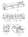
- Figure 1 is a perspective view of an elongated coil form with a tabbed conductive strip ready to be disposed therealong;
- Figure 2 is a plan view of the coil form and conductive strip of Figure 1, joined together Nith exemplary wire ends connected to the strip;
- Figure 3 is an end view of a completed coil as seen in the direction of coil form elongation; and
- Figure 4 is a perspective view of a plurality of completed coils.
- Corresponding reference characters indicate corresponding parts throughout the several views of the drawing.
- The exemplifications set out herein illustrate a preferred embodiment of the invention in one form thereof and such exemplifications are not to be construed as limiting the scope of the disclosure or the scope of the invention in any manner.
- Referring now to the drawing generally, a plurality of coils, as illustrated in Fig. 4, are concurrently formed about an
elongated coil form 11 of insulating material of, for example, cardboard or the like, with this coil form being a generally hollow tubular configuration with a plurality of holes, such as 13, arranged along one surface and extending in the direction of elongation. Eachhole 13 communicates with thehollow opening 15 of the coil form. A firstconductive strip 17, having a plurality of upstanding tabs, such as 19 and 21, has each of its tabs aligned with a corresponding coil form opening, and theform 11 andstrip 17 are juxtaposed by passing the tab portions into the openings until the strip abuts the coil form with the several tabs extending about half way through thehollow interior 15 of the coil form.Conductive strip 17 is then temporarily held in position disposed along the coil form by applyingtape - A plurality of first wire ends 27, 29 and 31 from a like plurality of wire sources are connected to the
strip 17, for example by soldering each wire end to the strip. This soldering may be accomplished prior to severing the previously completed coil set from the plurality of wire sources and the wire sections between the new coil form, and prior calls thereafter simply broken or cut by an operator, if desired. There are, of course, as many wire ends and wire sources as coils to be simultaneously formed. Aprotective insulating strip 37 may next be placed over theconductive strip 17 to insure that theconductive metal strip 17 does not damage the insulation on the first or innermost coil layer, as the coils are formed. - The
coil form 11,conductive strip 17, insulating or protectingstrip 37, and attached wire ends, are then revolved, generally about the axis of elongation of the coil form, with the several wire leads from the respective wire sources being guided so as to layer wind the plurality of coils. Further strips of insulating material in the form of paper like insulating layers may be periodically interposed to isolate each coil layer from the succeeding coil layer. - Upon completion of the winding process, a further
protective insulating strip 39 is applied along the outer surface of each of the wound coils and thereafter a secondconductive strip 41 is disposed along the coils, again in the general direction of coil form elongation to provide terminals for connecting the respective coil leads at the outer periphery of the several coils.Strip 41 will be configured substantially the same asstrip 17 and will includeconductive tabs 43 upstanding from the strip surface, which tabs provide a second terminal for connecting the coil in its intended environment. Thisouter strip 41 may be held in position by wrapping the coils with tape or by an axial strip ofprotective tape 46 and of course has the leads from the outer coil layers connected thereto, for example by soldering, as previously described. - Either immediately before or immediately after the sodlering of the wire leads to the
outer strip 41, the coil leads are cut from their respective wire sources to free the stick wound coil assembly therefrom. Individual coils may then be severed from other of the coils in the assembly by a slicing or cutting operation generally along a plane perpendicular to the axis of elongation of the coil form and, of course, lying between adjacent coils on the form. This cutting or slicing operation will severouter strip 41 and any associated tape,protective strip 39, the several layers of insulating paper,protective strip 37,conductive strip 17 and the insulatingtubular form 11. After slicing off an individual coil, its corresponding inner tab, such as 45 in Fig. 3, is normally bent from the position illustrated in Fig. 3 so that that tab extends in the direction of elongation of the original form and beyond the surface of the coil for ready attachment to other circuit components, as illustrated bytab 44 in Fig. 4. In Fig. 4, the coil associated withtab 44 has been omitted to more clearly illustrate the manner in whichtab 44 is bent outwardly for ready attachment. - The conductive strips 1 7 and 41 are formed from a continuous strip of tin plated brass which is cut and bent to form the particular strip configuration illustrated. This means that the distance between successive conductive tabs, such as 19 and 21, will be about the same as the depth of penetration of those tabs into the hollow coil form interior, and in the illustrated environment, this is about one-half the width of the coil form opening 15. Actually the tabs, such as 19 and 21 will extend into the coil form interior somewhat less than the distance separating those two consecutive tabs by the
coil form 11 wall thickness and the thickness of thesmall segment 47 which remains in the plane of the main portion ofstrip 17. - As best seen in Fig. 2, the
conductive strip 17 7 is seen to include a plurality of relativelywider sections 49, including the soldering pad portion of the strip upon which the coils are to be wound, separated by intermediate relatively more narrow sections, such as 51, along which the form is to be cut upon completion of the winding of the coils. The length of the conductive tab should be less than the width of theopening 15 in the coil form, and as noted earlier, is frequently about one-half this width. The hole, such as 13, in the cardboard tube orcoil form 11, should be relatively close to the edge of the finished coil so as to allow the tab to be bent outwardly and extend past the coil edge, as illustrated in Fig. 4, by an amount sufficient to be useful for subsequent circuit connecting purposes. Of course, the hole, such as 13, in the form must not be so close to the edge of the finished coil as to unduly weaken the coil. These factors should all be considered when determining the location and size of theholes 13, as well as thegeneral cleavage line 53, along which two adjacent coils are to be separated. - Holes, such as 35, are used during the manufacture of the strips to aid in moving the strips through cutting and forming dies.
- From the foregoing it is now apparent that a novel method of forming a plurality of coils of wire, as well as a novel coil form arrangement have been disclosed meeting the objects and advantageous features set out hereinbefore ag well as others and that modifactions as to the precise configurations, shapes and details may be made by those having ordinary skill in the art without departing from the spirit of the invention or the scope thereof as set out by the claims which follow.
Claims (5)
Priority Applications (1)
| Application Number | Priority Date | Filing Date | Title |
|---|---|---|---|
| AT81300461T ATE5447T1 (en) | 1980-03-17 | 1981-02-04 | METHOD OF WINDING COILS. |
Applications Claiming Priority (2)
| Application Number | Priority Date | Filing Date | Title |
|---|---|---|---|
| US131258 | 1980-03-17 | ||
| US06/131,258 US4347659A (en) | 1980-03-17 | 1980-03-17 | Method of making stick wound coils |
Publications (2)
| Publication Number | Publication Date |
|---|---|
| EP0036245A1 EP0036245A1 (en) | 1981-09-23 |
| EP0036245B1 true EP0036245B1 (en) | 1983-11-23 |
Family
ID=22448640
Family Applications (1)
| Application Number | Title | Priority Date | Filing Date |
|---|---|---|---|
| EP81300461A Expired EP0036245B1 (en) | 1980-03-17 | 1981-02-04 | Method of winding coils |
Country Status (9)
| Country | Link |
|---|---|
| US (1) | US4347659A (en) |
| EP (1) | EP0036245B1 (en) |
| JP (1) | JPS609651B2 (en) |
| AT (1) | ATE5447T1 (en) |
| AU (1) | AU523220B2 (en) |
| CA (1) | CA1164636A (en) |
| DE (1) | DE3161459D1 (en) |
| GB (1) | GB2072140A (en) |
| ZA (1) | ZA81632B (en) |
Families Citing this family (2)
| Publication number | Priority date | Publication date | Assignee | Title |
|---|---|---|---|---|
| JPS58153294A (en) * | 1982-03-04 | 1983-09-12 | Mitsubishi Electric Corp | Semiconductor storage device |
| JP3167679B2 (en) * | 1998-06-09 | 2001-05-21 | ファナック株式会社 | Stator winding method |
Family Cites Families (11)
| Publication number | Priority date | Publication date | Assignee | Title |
|---|---|---|---|---|
| US1142027A (en) * | 1912-04-03 | 1915-06-08 | Roeblings John A Sons Co | Solenoid. |
| US1625465A (en) * | 1925-04-03 | 1927-04-19 | Kellogg Switchboard & Supply | Coil |
| US1833221A (en) * | 1929-12-30 | 1931-11-24 | Chicago Transformer Corp | Electrostatically shielded transformer coil windings and method of making the same |
| US1968600A (en) * | 1933-06-09 | 1934-07-31 | Gen Electric | Electrical winding |
| US2706280A (en) * | 1950-12-30 | 1955-04-12 | Essex Wire Corp | Coil construction and method of making the same |
| FR1116670A (en) * | 1953-12-30 | 1956-05-09 | Sylvania Electric Prod | Electromagnetic coil |
| US3243752A (en) * | 1962-03-07 | 1966-03-29 | Allen Bradley Co | Encapsulated supported coils |
| US3278880A (en) * | 1963-05-27 | 1966-10-11 | Reynolds Metals Co | Strip conductor coils with terminals |
| US3277417A (en) * | 1965-03-15 | 1966-10-04 | Edwin C Rechel | Inductor and method of manufacture |
| US3373390A (en) * | 1967-06-07 | 1968-03-12 | Edwin C. Rechel | Electrical inductance and method |
| GB1175958A (en) * | 1968-02-29 | 1970-01-01 | Edwin Crafts Rechel | Electrical inductor method of manufacture thereof. |
-
1980
- 1980-03-17 US US06/131,258 patent/US4347659A/en not_active Expired - Lifetime
-
1981
- 1981-01-23 GB GB8102138A patent/GB2072140A/en not_active Withdrawn
- 1981-01-23 CA CA000369161A patent/CA1164636A/en not_active Expired
- 1981-01-30 ZA ZA00810632A patent/ZA81632B/en unknown
- 1981-02-04 EP EP81300461A patent/EP0036245B1/en not_active Expired
- 1981-02-04 AT AT81300461T patent/ATE5447T1/en not_active IP Right Cessation
- 1981-02-04 DE DE8181300461T patent/DE3161459D1/en not_active Expired
- 1981-02-27 AU AU67698/81A patent/AU523220B2/en not_active Ceased
- 1981-03-17 JP JP56038603A patent/JPS609651B2/en not_active Expired
Also Published As
| Publication number | Publication date |
|---|---|
| GB2072140A (en) | 1981-09-30 |
| ATE5447T1 (en) | 1983-12-15 |
| EP0036245A1 (en) | 1981-09-23 |
| ZA81632B (en) | 1982-02-24 |
| AU523220B2 (en) | 1982-07-15 |
| JPS56144511A (en) | 1981-11-10 |
| CA1164636A (en) | 1984-04-03 |
| AU6769881A (en) | 1981-09-24 |
| JPS609651B2 (en) | 1985-03-12 |
| US4347659A (en) | 1982-09-07 |
| DE3161459D1 (en) | 1983-12-29 |
Similar Documents
| Publication | Publication Date | Title |
|---|---|---|
| EP0475522B1 (en) | Transformer | |
| EP0002099A1 (en) | Slotted plate electrical terminal | |
| US4857877A (en) | Transformer having coaxial coils | |
| US2572956A (en) | Method of securing leads to commutators | |
| US4251911A (en) | Method of terminating coil windings | |
| CA1153049A (en) | Electrode terminals for electric motor winding | |
| US3445797A (en) | Inductor coil and bobbin with terminals | |
| EP0181185B1 (en) | Process for locating and connecting individual conductors in a multi-layer concentric lay cable | |
| US2794964A (en) | Electric wire connector | |
| US3967661A (en) | Insulation slitting and wire wrapping tool | |
| US2122894A (en) | Electrical coil | |
| US3373390A (en) | Electrical inductance and method | |
| US1704151A (en) | Spool for electrical instruments and the like | |
| US3278880A (en) | Strip conductor coils with terminals | |
| US4347659A (en) | Method of making stick wound coils | |
| US1833221A (en) | Electrostatically shielded transformer coil windings and method of making the same | |
| US1836948A (en) | Electric coil manufacture | |
| US4074065A (en) | Insulated wire splice | |
| US4232284A (en) | Ignition coil and electrical connector therefor | |
| US3731245A (en) | Inductor bobbin with terminals | |
| US4734974A (en) | Method of assembling an electrical coil and terminal therefor | |
| US3609833A (en) | Method of making ignition coils | |
| JPS5915166B2 (en) | How to manufacture a choke coil | |
| US2706280A (en) | Coil construction and method of making the same | |
| US2241761A (en) | Electrical coil and a method of making the same |
Legal Events
| Date | Code | Title | Description |
|---|---|---|---|
| PUAI | Public reference made under article 153(3) epc to a published international application that has entered the european phase |
Free format text: ORIGINAL CODE: 0009012 |
|
| AK | Designated contracting states |
Designated state(s): AT BE CH DE FR GB IT LU NL SE |
|
| 17P | Request for examination filed |
Effective date: 19811116 |
|
| ITF | It: translation for a ep patent filed | ||
| GRAA | (expected) grant |
Free format text: ORIGINAL CODE: 0009210 |
|
| AK | Designated contracting states |
Designated state(s): AT BE CH DE FR GB IT LI LU NL SE |
|
| REF | Corresponds to: |
Ref document number: 5447 Country of ref document: AT Date of ref document: 19831215 Kind code of ref document: T |
|
| REF | Corresponds to: |
Ref document number: 3161459 Country of ref document: DE Date of ref document: 19831229 |
|
| ET | Fr: translation filed | ||
| PG25 | Lapsed in a contracting state [announced via postgrant information from national office to epo] |
Ref country code: AT Effective date: 19840204 |
|
| PG25 | Lapsed in a contracting state [announced via postgrant information from national office to epo] |
Ref country code: SE Effective date: 19840205 |
|
| PG25 | Lapsed in a contracting state [announced via postgrant information from national office to epo] |
Ref country code: LU Free format text: LAPSE BECAUSE OF NON-PAYMENT OF DUE FEES Effective date: 19840229 Ref country code: LI Effective date: 19840229 Ref country code: CH Effective date: 19840229 Ref country code: BE Effective date: 19840229 |
|
| BERE | Be: lapsed |
Owner name: TECUMSEH PRODUCTS CY Effective date: 19840203 |
|
| PG25 | Lapsed in a contracting state [announced via postgrant information from national office to epo] |
Ref country code: NL Effective date: 19840901 |
|
| PLBE | No opposition filed within time limit |
Free format text: ORIGINAL CODE: 0009261 |
|
| STAA | Information on the status of an ep patent application or granted ep patent |
Free format text: STATUS: NO OPPOSITION FILED WITHIN TIME LIMIT |
|
| PG25 | Lapsed in a contracting state [announced via postgrant information from national office to epo] |
Ref country code: FR Free format text: LAPSE BECAUSE OF NON-PAYMENT OF DUE FEES Effective date: 19841031 |
|
| REG | Reference to a national code |
Ref country code: CH Ref legal event code: PL |
|
| PG25 | Lapsed in a contracting state [announced via postgrant information from national office to epo] |
Ref country code: DE Effective date: 19841101 |
|
| NLV4 | Nl: lapsed or anulled due to non-payment of the annual fee | ||
| 26N | No opposition filed | ||
| REG | Reference to a national code |
Ref country code: FR Ref legal event code: ST |
|
| GBPC | Gb: european patent ceased through non-payment of renewal fee | ||
| PG25 | Lapsed in a contracting state [announced via postgrant information from national office to epo] |
Ref country code: GB Effective date: 19881118 |
|
| EUG | Se: european patent has lapsed |
Ref document number: 81300461.1 Effective date: 19850604 |