EP0036177B1 - Fluidized bed heat exchanger - Google Patents
Fluidized bed heat exchanger Download PDFInfo
- Publication number
- EP0036177B1 EP0036177B1 EP81101788A EP81101788A EP0036177B1 EP 0036177 B1 EP0036177 B1 EP 0036177B1 EP 81101788 A EP81101788 A EP 81101788A EP 81101788 A EP81101788 A EP 81101788A EP 0036177 B1 EP0036177 B1 EP 0036177B1
- Authority
- EP
- European Patent Office
- Prior art keywords
- air
- gas
- tubes
- stage
- warm
- Prior art date
- Legal status (The legal status is an assumption and is not a legal conclusion. Google has not performed a legal analysis and makes no representation as to the accuracy of the status listed.)
- Expired
Links
Images

Classifications
-
- F—MECHANICAL ENGINEERING; LIGHTING; HEATING; WEAPONS; BLASTING
- F23—COMBUSTION APPARATUS; COMBUSTION PROCESSES
- F23L—SUPPLYING AIR OR NON-COMBUSTIBLE LIQUIDS OR GASES TO COMBUSTION APPARATUS IN GENERAL ; VALVES OR DAMPERS SPECIALLY ADAPTED FOR CONTROLLING AIR SUPPLY OR DRAUGHT IN COMBUSTION APPARATUS; INDUCING DRAUGHT IN COMBUSTION APPARATUS; TOPS FOR CHIMNEYS OR VENTILATING SHAFTS; TERMINALS FOR FLUES
- F23L15/00—Heating of air supplied for combustion
- F23L15/04—Arrangements of recuperators
- F23L15/045—Arrangements of recuperators using intermediate heat-transfer fluids
-
- B—PERFORMING OPERATIONS; TRANSPORTING
- B01—PHYSICAL OR CHEMICAL PROCESSES OR APPARATUS IN GENERAL
- B01J—CHEMICAL OR PHYSICAL PROCESSES, e.g. CATALYSIS OR COLLOID CHEMISTRY; THEIR RELEVANT APPARATUS
- B01J8/00—Chemical or physical processes in general, conducted in the presence of fluids and solid particles; Apparatus for such processes
- B01J8/18—Chemical or physical processes in general, conducted in the presence of fluids and solid particles; Apparatus for such processes with fluidised particles
- B01J8/24—Chemical or physical processes in general, conducted in the presence of fluids and solid particles; Apparatus for such processes with fluidised particles according to "fluidised-bed" technique
- B01J8/26—Chemical or physical processes in general, conducted in the presence of fluids and solid particles; Apparatus for such processes with fluidised particles according to "fluidised-bed" technique with two or more fluidised beds, e.g. reactor and regeneration installations
- B01J8/28—Chemical or physical processes in general, conducted in the presence of fluids and solid particles; Apparatus for such processes with fluidised particles according to "fluidised-bed" technique with two or more fluidised beds, e.g. reactor and regeneration installations the one above the other
-
- C—CHEMISTRY; METALLURGY
- C21—METALLURGY OF IRON
- C21B—MANUFACTURE OF IRON OR STEEL
- C21B9/00—Stoves for heating the blast in blast furnaces
- C21B9/14—Preheating the combustion air
-
- F—MECHANICAL ENGINEERING; LIGHTING; HEATING; WEAPONS; BLASTING
- F28—HEAT EXCHANGE IN GENERAL
- F28D—HEAT-EXCHANGE APPARATUS, NOT PROVIDED FOR IN ANOTHER SUBCLASS, IN WHICH THE HEAT-EXCHANGE MEDIA DO NOT COME INTO DIRECT CONTACT
- F28D13/00—Heat-exchange apparatus using a fluidised bed
-
- Y—GENERAL TAGGING OF NEW TECHNOLOGICAL DEVELOPMENTS; GENERAL TAGGING OF CROSS-SECTIONAL TECHNOLOGIES SPANNING OVER SEVERAL SECTIONS OF THE IPC; TECHNICAL SUBJECTS COVERED BY FORMER USPC CROSS-REFERENCE ART COLLECTIONS [XRACs] AND DIGESTS
- Y02—TECHNOLOGIES OR APPLICATIONS FOR MITIGATION OR ADAPTATION AGAINST CLIMATE CHANGE
- Y02E—REDUCTION OF GREENHOUSE GAS [GHG] EMISSIONS, RELATED TO ENERGY GENERATION, TRANSMISSION OR DISTRIBUTION
- Y02E20/00—Combustion technologies with mitigation potential
- Y02E20/34—Indirect CO2mitigation, i.e. by acting on non CO2directly related matters of the process, e.g. pre-heating or heat recovery
-
- Y—GENERAL TAGGING OF NEW TECHNOLOGICAL DEVELOPMENTS; GENERAL TAGGING OF CROSS-SECTIONAL TECHNOLOGIES SPANNING OVER SEVERAL SECTIONS OF THE IPC; TECHNICAL SUBJECTS COVERED BY FORMER USPC CROSS-REFERENCE ART COLLECTIONS [XRACs] AND DIGESTS
- Y02—TECHNOLOGIES OR APPLICATIONS FOR MITIGATION OR ADAPTATION AGAINST CLIMATE CHANGE
- Y02P—CLIMATE CHANGE MITIGATION TECHNOLOGIES IN THE PRODUCTION OR PROCESSING OF GOODS
- Y02P10/00—Technologies related to metal processing
- Y02P10/32—Technologies related to metal processing using renewable energy sources
Definitions
- the invention relates to a gas-fluidizable air preheater according to the preamble of claim 1.
- an air preheater in which there are two adjacent chambers in which there is a heat transfer medium made of sand or granular material. Below these chambers, tubes for the air to be heated and tubes for the warm gaseous medium run in the horizontal direction. Both types of pipe end approximately in the middle below each of the above-mentioned chambers, so that the gas exits here and flows through the granular material in the respective chamber and flows out from there via an outlet. Between the two chambers there are two types of connection paths at the level of the horizontal pipes, the pipes for the air to be heated leading through one type of connection paths and the pipes for the warm air through the other type of connection paths. Due to the ejector effect at the outlet ends of the respective pipes, d d s heat transfer medium is entrained from one chamber to the other via these connecting paths, so that the heat transfer medium is in a constant cycle via these connecting paths.
- a multi-stage fluidized bed gasifier is known from DE-A-2 746 158, in which a plurality of chambers for a granular material to be gasified are arranged one above the other. The granular material is fed in from above and moves from one chamber to the next via overflows. Pipes extend through all chambers in the vertical direction, through which a hot gas, e.g. B. helium flows, which heats and gasifies the granular material. The non-gasifiable ash is continuously discharged through an outlet. At the same time, process steam is introduced into the chambers containing the granular material, which whirls up this material and is discharged together with the evaporated material. The heat transfer takes place directly from the heat-carrying gas to the granular material to be evaporated. There is no intermediate heat transfer medium between the hot gas and the material to be heated.
- a hot gas e.g. B. helium flows
- the invention has for its object to develop a gas-fluidizable air preheater of the type mentioned, with which a high degree of heat transfer can be achieved and which works reliably.
- Fig. 1 shows a fluidized bed 1, in which vertical pipes 2, 3 according to the invention for dusty, warm gas 2 or air 3, which is to be preheated, are arranged.
- Fluidizing gas here C0 2 , which circulates in a closed system 5, is introduced at the bottom 4 of the fluidization chamber.
- the fluidizing gas keeps the sand or the grains floating in the fluidizing chamber 1, as a result of which they can withstand a high temperature and prevent gas from leaking into the atmosphere.
- the temperature of the warm gas 6, which emits heat to the sand 7, and the temperature of the air 8, which absorbs heat from the sand and thus indirectly from the warm gas, are shown in the vertical direction. It is important that the lowest gas temperature (Diagram point 9) is higher than the highest air temperature (diagram point 10).
- FIG. 2 shows sand or granulate 12 as an intermediate, fluidized bed between several vertical lines for warm, dust-containing gas 11 and preheated air 13.
- the sand is expediently blown in by fluidizing gas (at 14), inert gas, such as, for. B. C0 2 , N 2 or helium, which circulates in a closed system, kept floating. (See the schematic representation according to FIG. 2a with the air 15, the warm gas 16 and the fluidizing gas 17.)
- the inlet temperature of the warm gas is 16 800 ° C and its outlet temperature is 700 ° C.
- the inlet temperature of air 15 is 550 ° C and its outlet temperature is 650 ° C.
- the sand temperature is approx. 675 ° C.
- the heat exchanger works on the principle that heat is transferred from gas to sand and from sand to air.
- the sand serves as an intermediate and prevents direct contact between gas and air in the event of a leak.
- the heat transfer between sand and pipe surfaces (11, 13 in Fig. 2) can be very high, since fine-shaped sand (for example about 0.2 mm grain diameter) can be used and the sand assumes a high temperature.
- the C0 2 stream can be adjusted to the grain size.
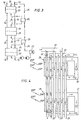
- the heat exchanger In order to be able to carry out a heat exchange of the warm gas and the air in countercurrent, the heat exchanger according to the invention is divided into stages (sections), as shown in FIG. 3. There are three stages in the embodiment. Warm, dusty gas 16 and air 15 are conducted in separate, vertical pipe systems through all stages 18, 19, 20, each of which contains a gas-flooded air preheater, each of which contains sand, grains or granules 21, 22 and 23, respectively, and of which each is fludged by, for example, C0 2 gas. The pressure drop in these stages does not become particularly large. The CO 2 gas (or N 2 ) used for fluidization is passed through the three stages (see FIG.
- CO 2 gas which has passed through the three stages and has reached a temperature of, for example, 675 ° C. , in heat exchangers 25, 26 in countercurrent gives off heat to upward flowing CO 2 gas.
- the downward flowing CO 2 gas has, for example, a temperature of 600 ° C. after passing through the heat exchanger 25 and a temperature of 525 ° C. after passing through the heat exchanger 26. It then passes through a water cooler in which water is heated and the gas is heated up 300 ° C is cooled. The gas is then cooled to the point where it can pass standard quality blowers.
- the inlet temperature of the warm dust-containing gas in the first stage 18 is 800 ° C
- the corresponding temperatures for stage 19 and stage 20 are 700-600 ° C and 600-500 ° C.
- C0 2 gas is passed in closed systems 30, 31 through the sand-filled fluidization chambers, and the vertical pipes for warm gas 32 and air 33 are alternately arranged adjacent; they practically interlock, which gives a good heat exchange.
- the sand, etc. prevents the CO of the warm gas from entering the air ducts.
Description
Die Erfindung betrifft einen gasfluidisierbaren Luftvorwärmer gemäß dem Oberbegriff des Anspruches 1.The invention relates to a gas-fluidizable air preheater according to the preamble of claim 1.
Es gibt Verfahren, bei denen ein warmes staubhaltiges CO-reiches Gas anfällt, dessen Energieinhalt man durch Vorwärmen von Luft teilweise zurückgewinnen möchte, siehe z. B. die englische Patentschrift 1 386 452. Es gibt horizontale Wärmeaustauscher für den genannten Zweck, doch sind diese u. a. bei hohem Staubgehalt weniger geeignet, da hier die Gefahr einer Rohrverstopfung groß ist.There are processes in which a warm, dusty, CO-rich gas is obtained, the energy content of which one would like to partially recover by preheating air. See, for example, British Patent 1,386,452. There are horizontal heat exchangers for the purpose mentioned, but these are u. a. less suitable with a high dust content, since there is a high risk of pipe clogging.
Ein Problem ist jedoch, daß CO und Luft, u. a. wegen der Explosionsgefahr und der Giftigkeit des CO, nicht gemischt we den dürfen. Man möchte einen guten Gegenstromeffekt erzielen, um die in dem warmen Mittel enthaltene Wärme zur Luftvorwärmung ausnutzen zu können. Es ist schwer, dieses mit der Fluidisierungstechnik zu kombinieren, und man möchte die Fluidisierungstechnik benutzen, damit das dazwischenliegende, die Wärme übertragende Mittel in der Lage ist, hohe Temperaturen anzunehmen, ohne daß deshalb der Druck hoch wird.One problem, however, is that CO and air, among others. a. due to the risk of explosion and the toxicity of CO, must not be mixed. One would like to achieve a good counterflow effect in order to be able to use the heat contained in the warm medium for preheating the air. It is difficult to combine this with the fluidization technique and one wants to use the fluidization technique so that the intermediate heat transfer agent is able to take on high temperatures without the pressure becoming high.
Aus der DE-A-2 925 649 ist ein Luftvorwärmer bekannt, bei dem zwei nebeneinanderliegende Kammern vorhanden sind, in denen sich ein Wärmeübertragungsmittel aus Sand oder kornförmigem Material befindet. Unterhalb dieser Kammern verlaufen in horizontaler Richtung Rohre für die zu erwärmende Luft und Rohre für das warme gasförmige Medium. Beide Rohrarten enden etwa in der Mitte unterhalb je einer der genannten Kammern, so daß das Gas hier austritt und durch das kornförmige Material in der jeweiligen Kammer hindurchströmt und von dort über einen Auslaß abströmt. Zwischen den beiden Kammern befinden sich in der Höhe der horizontalen Rohre zwei Arten von Verbindungswegen, wobei die Rohre für die zu erwärmende Luft durch die eine Art von Verbindungswegen und die Rohre für die warme Luft durch die andere Art von Verbindungswegen führen. Durch die Ejektorwirkung an den Austrittsenden der jeweiligen Rohre wird über diese Verbindungswege dds Wärmeübertragungsmittel von der einen in die andere Kammer mitgerissen, so daß über diese Verbindungswege das Wärmeübertragungsmittel sich in einem ständigen Kreislauf befindet.From DE-A-2 925 649 an air preheater is known in which there are two adjacent chambers in which there is a heat transfer medium made of sand or granular material. Below these chambers, tubes for the air to be heated and tubes for the warm gaseous medium run in the horizontal direction. Both types of pipe end approximately in the middle below each of the above-mentioned chambers, so that the gas exits here and flows through the granular material in the respective chamber and flows out from there via an outlet. Between the two chambers there are two types of connection paths at the level of the horizontal pipes, the pipes for the air to be heated leading through one type of connection paths and the pipes for the warm air through the other type of connection paths. Due to the ejector effect at the outlet ends of the respective pipes, d d s heat transfer medium is entrained from one chamber to the other via these connecting paths, so that the heat transfer medium is in a constant cycle via these connecting paths.
Aus der DE-A-2 746 158 ist ein mehrstufiger Wirbelschichtvergaser bekannt, bei dem mehrere Kammern für ein zu vergasendes kornförmiges Gut übereinander angeordnet sind. Das kornförmige Gut wird von oben zugeführt und wandert über Überläufe von einer Kammer in die nächste. Durch sämtliche Kammern erstrecken sich in vertikaler Richtung Rohre, durch die ein heißes Gas, z. B. Helium, strömt, welches das kornförmige Gut erhitzt und vergast. Die nicht vergasbare Asche wird laufend über einen Auslaß abgeführt. Gleichzeitig wird in die das kornförmige Gut enthaltenden Kammern Prozeßdampf eingeleitet, der dieses Gut aufwirbelt und der zusammen mit dem verdampften Gut abgeführt wird. Die Wärmeübertragung erfolgt unmittelbar von dem wärmetragenden Gas auf das zu verdampfende kornförmige Gut. Ein zwischengegeschaltetes Wärmeübertragungsmittel zwischen dem heißen Gas und dem zu erwärmenden Gut ist nicht vorhanden.A multi-stage fluidized bed gasifier is known from DE-A-2 746 158, in which a plurality of chambers for a granular material to be gasified are arranged one above the other. The granular material is fed in from above and moves from one chamber to the next via overflows. Pipes extend through all chambers in the vertical direction, through which a hot gas, e.g. B. helium flows, which heats and gasifies the granular material. The non-gasifiable ash is continuously discharged through an outlet. At the same time, process steam is introduced into the chambers containing the granular material, which whirls up this material and is discharged together with the evaporated material. The heat transfer takes place directly from the heat-carrying gas to the granular material to be evaporated. There is no intermediate heat transfer medium between the hot gas and the material to be heated.
Der Erfindung liegt die Aufgabe zugrunde, einen gasfluidisierbaren Luftvorwärmer der eingangs genannten Art zu entwickeln, mit dem ein hohes Maß an Wärmeübertragung erzielbar ist und der betriebssicher arbeitet.The invention has for its object to develop a gas-fluidizable air preheater of the type mentioned, with which a high degree of heat transfer can be achieved and which works reliably.
Zur Lösung dieser Aufgabe wird ein gasfluidisierbarer Luftwärmer gemäß dem Oberbegriff des Anspruches 1 vorgeschlagen, der die im kennzeichnenden Teil des Anspruches 1 genannten Merkmale hat.To solve this problem, a gas-fluidizable air warmer is proposed according to the preamble of claim 1, which has the features mentioned in the characterizing part of claim 1.
Vorteilhafte Weiterbildungen der Erfindung sind in den Unteransprüchen genannt.Advantageous developments of the invention are mentioned in the subclaims.
Hinsichtlich der Staubmassen folgt man deren natürlicher Bewegung, die vom Schwerkraft-Gesetz bestimmt wird, und kann somit ein Verstopfen der Rohre vermeiden. Das warme CO-haltige Gas wird aufgrund des dazwischenliegenden Wärmeübertragungsmittels nicht in die luftführenden Rohre eindringen. Durch das Vorhandensein mehrerer Stufen werden die genannten Vorteile damit kombiniert, daß man in jeder Stufe begrenzte Temperaturintervalle erhält. Die Explosionsgefahr wird behoben und der Wärmeaustauscheffekt wird gut.With regard to the dust masses, one follows their natural movement, which is determined by the law of gravity, and can thus avoid clogging of the pipes. The warm CO-containing gas will not penetrate the air-carrying pipes due to the heat transfer medium in between. The presence of several stages combines the advantages mentioned in that limited temperature intervals are obtained in each stage. The risk of explosion is eliminated and the heat exchange effect becomes good.
Anhand der in den Figuren gezeigten Ausführungsbeispiele soll die Erfindung näher erläutert werden. Es zeigen
- Fig. la, 1b, 2, 2a und 2b das Prinzip eines gasfluidisierbaren Luftvorwärmers,
- Fig. 3 einen Mehrstufenvorwärmer,
- Fig.4 ein detaillierter dargestelltes Ausführungsbeispiel eines Luftvorwärmers gemäß der Erfindung.
- La, 1b, 2, 2a and 2b the principle of a gas-fluidizable air preheater,
- 3 shows a multi-stage preheater,
- 4 shows a detailed embodiment of an air preheater according to the invention.
Fig. 1 zeigt ein fluidisiertes Bett 1, in dem vertikale Rohre 2, 3 gemäß der Erfindung für staubhaltiges, warmes Gas 2 bzw. Luft 3, die vorgewärmt werden soll, angeordnet sind. Fluidisierungsgas, hier C02, das in einem geschlossenen System 5 zirkuliert, wird am Boden 4 der Fluidisierungskammer eingeführt. Durch das Fluidisierungsgas werden in der Fluidisierungskammer 1 der Sand oder die Körner schwebend gehalten, wodurch dieser/ diese einer hohen Temperatur standhalten können und ein Hinauslecken von Gas in die Atmosphäre verhindern.Fig. 1 shows a fluidized bed 1, in which
In dem Diagramm gemäß Fig.lb ist in vertikaler Richtung einerseits die Temperatur des warmen Gases 6, welches Wärme an den Sand 7 abgibt, und andererseits die Temperatur der Luft 8 dargestellt, die Wärme vom Sand und damit indirekt vom warmen Gas aufnimmt. Wichtig ist, daß die niedrigste Gastemperatur (Diagrammpunkt 9) größer ist als die höchste Lufttemperatur (Diagrammpunkt 10).In the diagram according to FIG. 1b, the temperature of the warm gas 6, which emits heat to the
Fig.2 zeigt Sand oder Granulat 12 als dazwischenliegendes, fluidisiertes Bett zwischen mehreren vertikalen Leitungen für warmes, staubhaltiges Gas 11 und vorzuwärmende Luft 13. Der Sand wird durch das Einblasen von Fluidisierungsgas (bei 14), zweckmäßigerweise inertes Gas, wie z. B. C02, N2 oder Helium, das in einem geschlossenen System zirkuliert, schwebend gehalten. (Siehe die schematische Darstellung gemäß Fig. 2a mit der Luft 15, dem warmen Gas 16 und Fluidisierungsgas 17.)2 shows sand or
In dem gezeigten Beispiel, bei dem es sich um eine Stufe in einem gasfluidisierten Luftvorwärmer handelt, beträgt die Eingangstemperatur des warmen Gases 16 800°C und seine Ausgangstemperatur 700°C. Die Eingangstemperatur der Luft 15 beträgt 550°C und ihre Ausgangstemperatur 650°C. Die Sandtemperatur beträgt ca. 675° C.In the example shown, which is a stage in a gas-fluidized air preheater, the inlet temperature of the warm gas is 16 800 ° C and its outlet temperature is 700 ° C. The inlet temperature of
Der Wärmeaustauscher arbeitet nach dem Prinzip, daß Wärme von Gas auf den Sand und vom Sand auf die Luft übertragen wird. Der Sand dient als Zwischenmittel und verhindert einen direkten Kontakt zwischen Gas und Luft im Falle einer Undichtheit. Die Wärmeübertragung zwischen Sand und Rohroberflächen (11, 13 in Fig. 2) kann sehr hoch werden, da man feinkörmigen Sand (beispielsweise ca. 0,2 mm Korndurchmesser) verwenden kann und der Sand eine hohe Temperatur annimmt. Der C02-Strom kann der Korngröße angepaßt werden.The heat exchanger works on the principle that heat is transferred from gas to sand and from sand to air. The sand serves as an intermediate and prevents direct contact between gas and air in the event of a leak. The heat transfer between sand and pipe surfaces (11, 13 in Fig. 2) can be very high, since fine-shaped sand (for example about 0.2 mm grain diameter) can be used and the sand assumes a high temperature. The C0 2 stream can be adjusted to the grain size.
Um einen Wärmeaustausch des warmen Gases und der Luft in Gegenstrom durchführen zu können, wird der Wärmeaustauscher nach der Erfindung in Stufen (Sektionen) aufgeteilt, wie es Fig. 3 zeigt. In dem Ausführungsbeispiel sind drei Stufen vorhanden. Warmes, staubhaltiges Gas 16 und Luft 15 werden in separaten, vertikalen Rohrsystemen durch alle Stufen 18, 19, 20 geleitet, von denen jede einen gasfludisierten Luftvorwärmer enthält, von denen jede Sand, Körner oder Granulat 21, 22 bzw. 23 enthält und von denen jede durch beispielsweise C02-Gas fludisiert wird. Der Druckabfall in diesen Stufen wird nicht besonders groß. Das zur Fluidisierung benutzte C02-Gas (oder N2) wird in der Weise durch die drei Stufen (siehe 24) geleitet, daß C02-Gas, welches die drei Stufen passiert hat und dabei eine Temperatur von beispielsweise 675° C angenommen hat, in Wärmeaustauschern 25, 26 im Gegenstrom Wärme an nach oben strömendes C02-Gas abgibt. Das nach unten strömende C02-Gas hat nach dem Passieren des Wärmeaustauschers 25 beispielsweise eine Temperatur von 600° C und nach dem Passieren des Wärmeaustauschers 26 eine Temperatur von 525° C. Es passiert anschließend einen Wasserkühler, in dem Wasser erhitzt und das Gas auf ca. 300°C abgekühlt wird. Das Gas ist danach so weit abgekühlt, daß es Gebläse von Standardqualität passieren kann.In order to be able to carry out a heat exchange of the warm gas and the air in countercurrent, the heat exchanger according to the invention is divided into stages (sections), as shown in FIG. 3. There are three stages in the embodiment. Warm,
Die Eingangstemperatur des warmen staubhaltigen Gases in die erste Stufe 18 beträgt 800°C, die Ausgangstemperatur 700°C, und die entsprechenden Temperaturen für die Stufe 19 bzw. Stufe 20 betragen 700-600°C bzw. 600-500°C. Dies ist auch links in Fig.4 veranschaulicht, wo zwei Stufen 28, 29 gezeigt sind. C02-Gas wird in geschlossenen Systemen 30, 31 durch die sandgefüllten Fluidisierungskammern geleitet, und die vertikalen Rohre für warmes Gas 32 bzw. Luft 33 sind abwechselnd benachbart angeordnet; sie greifen also quasi ineinander, wodurch man einen guten Wärmeaustausch erhält. Durch den Sand usw. wird das CO des warmen Gases daran gehindert, in die Luftleitungen zu gelangen. Es versteht sich, daß die Verteilung und gegenseitige Anordnung der vertikalen Rohre untereinander in seitlicher Richtung oder nach unten hin auch anders beschaffen sein kann, als in Fig. 4 gezeigt.The inlet temperature of the warm dust-containing gas in the
Claims (3)
Applications Claiming Priority (2)
| Application Number | Priority Date | Filing Date | Title |
|---|---|---|---|
| SE8002101 | 1980-03-18 | ||
| SE8002101A SE420763B (en) | 1980-03-18 | 1980-03-18 | GAS FLUIDIZED AIR CONVERTER |
Publications (2)
| Publication Number | Publication Date |
|---|---|
| EP0036177A1 EP0036177A1 (en) | 1981-09-23 |
| EP0036177B1 true EP0036177B1 (en) | 1983-12-21 |
Family
ID=20340547
Family Applications (1)
| Application Number | Title | Priority Date | Filing Date |
|---|---|---|---|
| EP81101788A Expired EP0036177B1 (en) | 1980-03-18 | 1981-03-11 | Fluidized bed heat exchanger |
Country Status (6)
| Country | Link |
|---|---|
| EP (1) | EP0036177B1 (en) |
| JP (1) | JPS56142385A (en) |
| BR (1) | BR8101596A (en) |
| DE (1) | DE3161683D1 (en) |
| SE (1) | SE420763B (en) |
| SU (1) | SU1085517A3 (en) |
Families Citing this family (1)
| Publication number | Priority date | Publication date | Assignee | Title |
|---|---|---|---|---|
| US6034100A (en) * | 1993-03-10 | 2000-03-07 | Otsuka Pharmaceutical Co., Ltd. | Method for inhibiting cytokine secretion |
Citations (5)
| Publication number | Priority date | Publication date | Assignee | Title |
|---|---|---|---|---|
| CH472647A (en) * | 1967-03-13 | 1969-05-15 | Applic Electro Thermiques Soc | Heat exchange method and apparatus |
| DE2746158A1 (en) * | 1977-10-14 | 1979-04-19 | Ght Hochtemperaturreak Tech | Fluidised bed gasifier - with alternate peripheral and central overflows on plates and straight heating tubes |
| US4158036A (en) * | 1977-05-02 | 1979-06-12 | Allied Chemical Corporation | Fluid bed heat recovery apparatus |
| DE2925649A1 (en) * | 1978-07-04 | 1980-01-17 | Stal Laval Apparat Ab | HEAT EXCHANGER FOR THE TRANSFER OF HEAT BETWEEN GAS-SHAPED MEDIA |
| WO1980002193A1 (en) * | 1979-04-09 | 1980-10-16 | Norsk Viftefab As | Heat exchanger for gases |
Family Cites Families (1)
| Publication number | Priority date | Publication date | Assignee | Title |
|---|---|---|---|---|
| DD100017A5 (en) * | 1971-11-01 | 1973-09-05 |
-
1980
- 1980-03-18 SE SE8002101A patent/SE420763B/en unknown
-
1981
- 1981-03-11 DE DE8181101788T patent/DE3161683D1/en not_active Expired
- 1981-03-11 EP EP81101788A patent/EP0036177B1/en not_active Expired
- 1981-03-16 JP JP3775381A patent/JPS56142385A/en active Pending
- 1981-03-17 SU SU813256348A patent/SU1085517A3/en active
- 1981-03-18 BR BR8101596A patent/BR8101596A/en unknown
Patent Citations (5)
| Publication number | Priority date | Publication date | Assignee | Title |
|---|---|---|---|---|
| CH472647A (en) * | 1967-03-13 | 1969-05-15 | Applic Electro Thermiques Soc | Heat exchange method and apparatus |
| US4158036A (en) * | 1977-05-02 | 1979-06-12 | Allied Chemical Corporation | Fluid bed heat recovery apparatus |
| DE2746158A1 (en) * | 1977-10-14 | 1979-04-19 | Ght Hochtemperaturreak Tech | Fluidised bed gasifier - with alternate peripheral and central overflows on plates and straight heating tubes |
| DE2925649A1 (en) * | 1978-07-04 | 1980-01-17 | Stal Laval Apparat Ab | HEAT EXCHANGER FOR THE TRANSFER OF HEAT BETWEEN GAS-SHAPED MEDIA |
| WO1980002193A1 (en) * | 1979-04-09 | 1980-10-16 | Norsk Viftefab As | Heat exchanger for gases |
Also Published As
| Publication number | Publication date |
|---|---|
| JPS56142385A (en) | 1981-11-06 |
| SE420763B (en) | 1981-10-26 |
| DE3161683D1 (en) | 1984-01-26 |
| SU1085517A3 (en) | 1984-04-07 |
| SE8002101L (en) | 1981-09-19 |
| BR8101596A (en) | 1981-09-22 |
| EP0036177A1 (en) | 1981-09-23 |
Similar Documents
| Publication | Publication Date | Title |
|---|---|---|
| AT401418B (en) | METHOD AND DEVICE FOR CONTROLLING THE FUNCTION OF A FLUIDIZED BED REACTOR WITH A CIRCULATING FLUIDED LAYER | |
| DE602006000936T2 (en) | Circulating fluidized bed combustion plant with convertible combustion process | |
| DE3131514C1 (en) | Method for cooling refrigerated goods beds and stowing device for carrying out the method | |
| DE69628280T2 (en) | FLOW BED ARRANGEMENT WITH FLOW COMPENSATION | |
| DE102021204176A1 (en) | Co-current counter-current regenerative shaft kiln and method for firing carbonate rock | |
| EP0036177B1 (en) | Fluidized bed heat exchanger | |
| DE4200244A1 (en) | METHOD AND DEVICE FOR COOLING THE HOT SOLIDS OF A FLUIDIZED BED REACTOR | |
| EP1080325B1 (en) | Fluidized bed combustion system with steam generation | |
| EP0036409B1 (en) | Method of cooling hot bulk material | |
| DE4233140A1 (en) | Reducing iron@-contg. material - using reducing gas under pressure in several fluidised bed reactors | |
| DE2715790A1 (en) | FLOATING GAS PREHEATER FOR FINE GOODS | |
| EP3441127B1 (en) | Absorption column equipped with external heat exchange circuit | |
| DE3345235A1 (en) | Fluidised bed having a heat exchanger arrangement | |
| EP0157901A2 (en) | Fluidized-bed furnace | |
| WO2012038109A2 (en) | Method and installation for generating steam | |
| CH496628A (en) | Method and device for drying sewage sludge using a hot gaseous medium | |
| AT376144B (en) | DEVICE FOR COOLING, DESulphurizing and Reheating Smoke Gases | |
| DE2064032A1 (en) | Two step cement clinker cooler - with double walled second stage oscillating channel conveyor cooler | |
| EP0192144B1 (en) | Energy and/or particles exchange device between fines and a fluid | |
| DE2905281A1 (en) | ARRANGEMENT FOR THE SUPPLY AND DISTRIBUTION OF DUSTIC GAS | |
| DE3511877A1 (en) | CONTINUOUS STEAM GENERATOR | |
| WO1999024773A1 (en) | Device enabling heat exchange between a heat carrying fluid and a solid | |
| DE19805897C1 (en) | Final cooling of anhydrous alumina produced from aluminium hydroxide in fluidised bed with simple heat recovery | |
| DE2925649A1 (en) | HEAT EXCHANGER FOR THE TRANSFER OF HEAT BETWEEN GAS-SHAPED MEDIA | |
| DE3343480A1 (en) | Process and apparatus for the fluidising and simultaneous cooling of fluidised bed material in a fluidised bed furnace |
Legal Events
| Date | Code | Title | Description |
|---|---|---|---|
| PUAI | Public reference made under article 153(3) epc to a published international application that has entered the european phase |
Free format text: ORIGINAL CODE: 0009012 |
|
| AK | Designated contracting states |
Designated state(s): CH DE FR GB |
|
| 17P | Request for examination filed |
Effective date: 19820128 |
|
| GRAA | (expected) grant |
Free format text: ORIGINAL CODE: 0009210 |
|
| AK | Designated contracting states |
Designated state(s): CH DE FR GB LI |
|
| REF | Corresponds to: |
Ref document number: 3161683 Country of ref document: DE Date of ref document: 19840126 |
|
| ET | Fr: translation filed | ||
| PG25 | Lapsed in a contracting state [announced via postgrant information from national office to epo] |
Ref country code: LI Effective date: 19840331 Ref country code: CH Effective date: 19840331 |
|
| PLBE | No opposition filed within time limit |
Free format text: ORIGINAL CODE: 0009261 |
|
| STAA | Information on the status of an ep patent application or granted ep patent |
Free format text: STATUS: NO OPPOSITION FILED WITHIN TIME LIMIT |
|
| PG25 | Lapsed in a contracting state [announced via postgrant information from national office to epo] |
Ref country code: FR Free format text: LAPSE BECAUSE OF NON-PAYMENT OF DUE FEES Effective date: 19841130 |
|
| REG | Reference to a national code |
Ref country code: CH Ref legal event code: PL |
|
| PG25 | Lapsed in a contracting state [announced via postgrant information from national office to epo] |
Ref country code: DE Effective date: 19841201 |
|
| 26N | No opposition filed | ||
| REG | Reference to a national code |
Ref country code: FR Ref legal event code: ST |
|
| GBPC | Gb: european patent ceased through non-payment of renewal fee | ||
| PG25 | Lapsed in a contracting state [announced via postgrant information from national office to epo] |
Ref country code: GB Effective date: 19881118 |