EP0035891A1 - Face seal system - Google Patents
Face seal system Download PDFInfo
- Publication number
- EP0035891A1 EP0035891A1 EP81300950A EP81300950A EP0035891A1 EP 0035891 A1 EP0035891 A1 EP 0035891A1 EP 81300950 A EP81300950 A EP 81300950A EP 81300950 A EP81300950 A EP 81300950A EP 0035891 A1 EP0035891 A1 EP 0035891A1
- Authority
- EP
- European Patent Office
- Prior art keywords
- seal member
- seal
- shaft
- axially
- wall
- Prior art date
- Legal status (The legal status is an assumption and is not a legal conclusion. Google has not performed a legal analysis and makes no representation as to the accuracy of the status listed.)
- Granted
Links
Images

Classifications
-
- F—MECHANICAL ENGINEERING; LIGHTING; HEATING; WEAPONS; BLASTING
- F01—MACHINES OR ENGINES IN GENERAL; ENGINE PLANTS IN GENERAL; STEAM ENGINES
- F01D—NON-POSITIVE DISPLACEMENT MACHINES OR ENGINES, e.g. STEAM TURBINES
- F01D25/00—Component parts, details, or accessories, not provided for in, or of interest apart from, other groups
- F01D25/18—Lubricating arrangements
- F01D25/183—Sealing means
- F01D25/186—Sealing means for sliding contact bearing
-
- F—MECHANICAL ENGINEERING; LIGHTING; HEATING; WEAPONS; BLASTING
- F04—POSITIVE - DISPLACEMENT MACHINES FOR LIQUIDS; PUMPS FOR LIQUIDS OR ELASTIC FLUIDS
- F04D—NON-POSITIVE-DISPLACEMENT PUMPS
- F04D29/00—Details, component parts, or accessories
- F04D29/08—Sealings
- F04D29/10—Shaft sealings
- F04D29/12—Shaft sealings using sealing-rings
-
- F—MECHANICAL ENGINEERING; LIGHTING; HEATING; WEAPONS; BLASTING
- F16—ENGINEERING ELEMENTS AND UNITS; GENERAL MEASURES FOR PRODUCING AND MAINTAINING EFFECTIVE FUNCTIONING OF MACHINES OR INSTALLATIONS; THERMAL INSULATION IN GENERAL
- F16J—PISTONS; CYLINDERS; SEALINGS
- F16J15/00—Sealings
- F16J15/16—Sealings between relatively-moving surfaces
- F16J15/34—Sealings between relatively-moving surfaces with slip-ring pressed against a more or less radial face on one member
- F16J15/38—Sealings between relatively-moving surfaces with slip-ring pressed against a more or less radial face on one member sealed by a packing
-
- F—MECHANICAL ENGINEERING; LIGHTING; HEATING; WEAPONS; BLASTING
- F05—INDEXING SCHEMES RELATING TO ENGINES OR PUMPS IN VARIOUS SUBCLASSES OF CLASSES F01-F04
- F05D—INDEXING SCHEME FOR ASPECTS RELATING TO NON-POSITIVE-DISPLACEMENT MACHINES OR ENGINES, GAS-TURBINES OR JET-PROPULSION PLANTS
- F05D2220/00—Application
- F05D2220/40—Application in turbochargers
-
- F—MECHANICAL ENGINEERING; LIGHTING; HEATING; WEAPONS; BLASTING
- F16—ENGINEERING ELEMENTS AND UNITS; GENERAL MEASURES FOR PRODUCING AND MAINTAINING EFFECTIVE FUNCTIONING OF MACHINES OR INSTALLATIONS; THERMAL INSULATION IN GENERAL
- F16C—SHAFTS; FLEXIBLE SHAFTS; ELEMENTS OR CRANKSHAFT MECHANISMS; ROTARY BODIES OTHER THAN GEARING ELEMENTS; BEARINGS
- F16C2360/00—Engines or pumps
- F16C2360/23—Gas turbine engines
- F16C2360/24—Turbochargers
-
- F—MECHANICAL ENGINEERING; LIGHTING; HEATING; WEAPONS; BLASTING
- F16—ENGINEERING ELEMENTS AND UNITS; GENERAL MEASURES FOR PRODUCING AND MAINTAINING EFFECTIVE FUNCTIONING OF MACHINES OR INSTALLATIONS; THERMAL INSULATION IN GENERAL
- F16C—SHAFTS; FLEXIBLE SHAFTS; ELEMENTS OR CRANKSHAFT MECHANISMS; ROTARY BODIES OTHER THAN GEARING ELEMENTS; BEARINGS
- F16C33/00—Parts of bearings; Special methods for making bearings or parts thereof
- F16C33/72—Sealings
- F16C33/74—Sealings of sliding-contact bearings
Definitions
- This invention relates to a face seal system. More specifically, this invention relates to an improved face seal system particularly designed for co-operation with a thrust bearing system in a turbocharger for sealing passage of a turbocharger shaft through a wall.
- a turbine wheel and a compressor impeller are carried on a common shaft.
- the turbine wheel is received-within a turbine housing for communication with exhaust gases from an engine, whereby the shaft is rotatably driven during engine operation.
- the shaft is supported by suitable journal bearings and thrust bearings within a centre housing connected between the turbine housing and a compressor housing receiving the compressor impeller.
- the exhaust gas driven turbine wheel thereby drives the compressor impeller to compress charge air for supply to the intake of the engine, all in a well-known manner.
- the rotating shaft in a turbocharger is capable of being driven at relatively high rotational speeds, such as on the order of about 100,000 RPM or more.
- rotational speeds require the use of precision bearing components together with an effective system of bearing lubrication.
- lubricating oil is commonly pumped under pressure to the turbocharger centre housing for lubricating the shaft bearings to prevent excessive bearing heating and wear.
- turbocharger shaft bearings without leakage of oil from the centre housing, particularly into the compressor housing, has long been a troublesome problem in the design of turbochargers.
- localised fluid pressure in the region between the back side of the compressor impeller and the backplate wall separating the centre housing from the compressor housing is frequently less than the fluid pressure within the centre housing.
- a substantial pressure differential is created tending to cause oil leakage from the centre housing around the rotating shaft and into the compressor housing.
- This leakage tendency is substantially enhanced by the high rotational speed of the shaft causing relatively rapid wear of sealing components such as seal rings and the like.
- seal systems have been proposed for sealing passage of the turbocharger shaft through the backplate separating the centre and compressor housings of the turbocharger.
- Some of these systems include various seal ring arrangements intended to block oil leakage through the shaft passage. See, for example, U.S. Patent Nos. 3,397,947., 3,077,296., 2,953,416., 2,785,022., 2,362,667., and 2,054,219. Hoever, these systems are not totally satisfactory in that the seal rings tend to exhibit relatively high rates of wear resulting in premature leakage.
- Other arrangements have included slingers and the like in an attempt to move oil away from the region of the leakage path. See, for example U.S. Patent Nos.
- An object of the present invention is to provide a face seal system in which the problems and disadvantages of the prior art are overcome and which is quickly and easily mounted directly into the wall separating the turbocharger compressor and centre housing, and including means for varying sealing forces in response to the pressure differential across the said wall to limit seal wear.
- a seal system for sealing passage of a rotatable shaft through an opening formed in a wall separating regions subject to differential fluid pressures, in which the wall has in it an axially open annular recess bounded at its radially inner extent by an axially extending tubular flange concentrical about the shaft, the system comprising a generally annular seal member received axially in the recess,and including a seal face for sealing engagement with respect to the shaft spring means in the recess for urging the seal face of the seal member into sealing engagement with respect to the shaft, means on the wall for preventing rotation of the seal member with the shaft, and an annular resilient seal ring concentrically between the seal member and the flange for preventing passage of fluid therebetween.
- the system may include a thrust bearing system having a thrust collar on the shaft for rotation therewith, the seal face comprising an axially presented face for sealing engagement with the thrust collar, the spring means being interposed between the wall and the seal member for urging the latter member axially away from the wall toward the thrust collar.
- the spring means comprise an annular thrust washer in bearing engagement with one axial end of the seal member and a spring under compression between the thrust washer and the wall.
- the spring comprises a relatively low rate helical spring having a generally conical cross section for compression substantially into a single plane.
- the seal member has an axially elongated slot in its periphery
- the rotation preventing means comprises a radially inwardly projecting anti-rotation lug on the wall for registering with the said seal member slot.
- the spring means may comprise an annular thrust washer in bearing engagement with one axial end of the seal member and a spring under compression between the thrust washer and the wall, the said thrust washer having in its periphery a slot for registering with the anti-rotation lug.
- the anti-rotation lug may be axially spaced from the portion of the wall engaged by the spring,the thrust washer being inserted into the recess past the lug, and then turned so that the lug axially retains the thrust washer within the recess.
- the system is particularly applicable in a turbocharger, for sealing passage of the turbocharger shaft where it passes through a compressor backplate separating a turbocharger centre housing from a compressor housing.
- FIGURE 1 A portion of a turbocharger 10 is shown in FIGURE 1 and comprises a compressor impeller 12 carried on a rotatable shaft 16 within a compressor housing 14.
- the shaft 16 extends from the impeller 12 through a turbocharger centre housing 18 for connection to a turbine carried within a turbine housing ( hot shown).
- exhaust gases from an internal combustion engine are supplied to the turbine (not shown) to rotatably drive the turbine, and thereby also rotatably drive the turbocharger shaft 16.
- Such driving causes corresponding rotation of the impeller 12 within the compressor housing 14 serving to draw air through a compressor inlet 22 for compression, and discharge through'a diffuser 24 and an outlet volute 26 to the intake ( not shown) of an internal combustion engine.
- the centre housing 18 and the compressor housing 14 are separated by a common wall, or compressor backplate 28.
- the shaft 16 extends through the centre housing 18, and further through a central passage 32 in the compressor backplate 28 to the compressor housing 14.
- the compressor impeller 12 is received over one end of the shaft.16 within the compressor housing 14, and is suitably secured as by a nut 34 for rotation therewith.
- the back side 36 of the impeller 12 is axially spaced slightly away from the backplate 28 so as to avoid contact therewith during impeller rotation.
- pressure in the vicinity of the backplate shaft passage 32 may vary between a superatmospheric pressure at relatively high speed impeller roation to a subatmospheric pressure at relatively low speed impeller rotation , such as during engine idling conditions.
- pressure within the centre housing is normally near atmospheric pressure for all conditions of turbocharger operation, potential exists for leakage of fluid such as lubricating oil from the centre housing 18 through the shaft passage 32 and into the compressor housing 14 whenever the centre housing pressure is the larger pressure. That is, the pressure differential through the passage 32 may function during at least some periods of turbocharger operation to pump lubricating oil from the centre housing 18 into the compressor housing 14. When this occurs, it is necessary to provide a sealing system to prevent the leakage of oil through the backplate shaft passage 32.
- a face seal system 50 of this invention is incorporated into the compressor backplate 28 within the centre housing 18, and reacts between the backplate 28 and a thrust bearing system 40 carried about the turbocharger shaft 16. More specifically, the thrust bearing system 40 is provided for controlling undesirable axial excursions of the shaft 16, and thereby functions to locate precisely the axial positions of the compressor impeller 12 and the turbine (not shown) within their respective housings.
- the thrust bearing system 40 comprises a thrust collar 45 snugly received over the shaft 16 for rotation therewith at a position abuttingly between an enlarged shaft portion 38 and a bushing-shaped spacer 46 interposed between the impeller 12 and the thrust collar 45.
- the thrust collar 45 has a radially.
- the face seal system 50 comprises a helical compression spring 62 having a relatively low spring rate received within a recess 64 formed within the backplate 28 and opening axially toward the interior of the centre housing 18.
- the recess 64 defines an annular flange 66 formed concentrically about and slightly spaced with respect to the spacer 46, and extending axially into the centre housing toward the thrust collar 45.
- the backplate 28 includes a plurality of anti-rotation lugs 70 projecting radially inwardly into the recess 64 to form a relatively small annular undercut 71 for reception and positioning of the seal system 50, as will be described in more detail.
- a thrust washer 68 includes at its periphery a plurality of slots 72 circumferentially arranged for registry with the anti-rotation lugs 70. on the centre housing Back-plate 28.
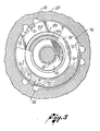
- the thrust washer 68 is thus receivable past the anti-rotation lugs 70, and is indexable with respect to the lugs 70 as illustrated in FIGURE 3 for reception within the recess 64 and retention therein By the lugs 70.
- the spring 62 biases the thrust washer 68 axially to the right as viewed in FIGURE 2 in engagement with. the anti-rotation lugs 70.
- the spring 62 is formed to have a conical cross section so as to have its coils compressible substantially into a single plane.
- a seal member 74 has a generally annular shape, and is formed from a suitable sealing composition such as carbon or the like.
- the seal member 74 includes about its periphery a plurality of slots 76 configured for registry with the anti-rotation lugs 70. The seal member 74 is thus received concentrically about the flange 66 with its slots 76 axially receiving the lugs 70 to prevent rotation of the seal member.
- the seal member 74 includes an axially presented seal face 78 for bearing and sealing engagement with the rotating thrust collar 45 mounted on the shaft 16.
- the seal member also includes an opposite axially presented face 79 for bearing engagement with the thrust washer 68.
- the axial length of the seal member 74 is chosen such. that the spring 62 urges the thrust washer 68 into engagement with the face 79 of the seal member 74, which correspondingly urges the sealing face 78 of the seal member 74 into sealing engagement with the thrust collar 45.
- An annular resilient seal ring 80 such as an 0-ring, is interposed radially Between the backplate flange 66 and the seal member 74 to seal against passage of fluids therebetween. Moreover, this seal ring 80 is axially positioned between the thrust washer 68 and a radially stepped shoulder 82, formed on the inner diameter of the seal member 74.
- the thrust washer 68 and the seal ring 80 combine to adjust the sealing force between the seal face 78 and the thrust collar 45. More specifically, as shown, the spring 62 normally biases the thrust washer 68 against the rear face 79 of the seal member 74 to urge the seal face 78 against the thrust collar 45.
- the present invention thus provides a pressure compensating face seal system which is quickly and easily mounted directly within the backplate of a turbocharger.
- the system includes a seal member of a high quality seal material such as carbon. Potential leakage between the seal member and the non-rotational backplate is prevented by a resilient seal ring. Potential leakage between the seal member and rotating components is prevented by a seal face which is variably force-loaded depending upon turbocharger operating characteristics. Since the seal system is mounted directly within the compressor backplate 28, no other leakage path is present.
Abstract
Description
- This invention relates to a face seal system. More specifically, this invention relates to an improved face seal system particularly designed for co-operation with a thrust bearing system in a turbocharger for sealing passage of a turbocharger shaft through a wall.
- In a turbocharger, a turbine wheel and a compressor impeller are carried on a common shaft. The turbine wheel is received-within a turbine housing for communication with exhaust gases from an engine, whereby the shaft is rotatably driven during engine operation. The shaft is supported by suitable journal bearings and thrust bearings within a centre housing connected between the turbine housing and a compressor housing receiving the compressor impeller. The exhaust gas driven turbine wheel thereby drives the compressor impeller to compress charge air for supply to the intake of the engine, all in a well-known manner.
- Typically, the rotating shaft in a turbocharger is capable of being driven at relatively high rotational speeds, such as on the order of about 100,000 RPM or more. Such rotational speeds require the use of precision bearing components together with an effective system of bearing lubrication. In this regard, lubricating oil is commonly pumped under pressure to the turbocharger centre housing for lubricating the shaft bearings to prevent excessive bearing heating and wear.
- The effective lubrication of turbocharger shaft bearings without leakage of oil from the centre housing, particularly into the compressor housing, has long been a troublesome problem in the design of turbochargers. Specifically, during normal operation of the turbocharger, localised fluid pressure in the region between the back side of the compressor impeller and the backplate wall separating the centre housing from the compressor housing is frequently less than the fluid pressure within the centre housing. Thus, a substantial pressure differential is created tending to cause oil leakage from the centre housing around the rotating shaft and into the compressor housing. This leakage tendency is substantially enhanced by the high rotational speed of the shaft causing relatively rapid wear of sealing components such as seal rings and the like.
- A wide variety of seal systems have been proposed for sealing passage of the turbocharger shaft through the backplate separating the centre and compressor housings of the turbocharger. Some of these systems include various seal ring arrangements intended to block oil leakage through the shaft passage. See, for example, U.S. Patent Nos. 3,397,947., 3,077,296., 2,953,416., 2,785,022., 2,362,667., and 2,054,219. Hoever, these systems are not totally satisfactory in that the seal rings tend to exhibit relatively high rates of wear resulting in premature leakage. Other arrangements have included slingers and the like in an attempt to move oil away from the region of the leakage path. See, for example U.S. Patent Nos. 3,494,679., and 4,157,834. However, these systems also are not altogether successful in eliminating leakage in commercial turbochargers. Still other systems have been proposed including the incorporation of cartridge-type pressure-responsive seal assemblies into the shaft passage between the compressor housing and centre housing. See, for example, U.S. Patent No. 2,393,944. However, these systems introduce into the turbocharger an additional and undesirable leakage path around the outer diameter of the seal cartridge.
- An object of the present invention is to provide a face seal system in which the problems and disadvantages of the prior art are overcome and which is quickly and easily mounted directly into the wall separating the turbocharger compressor and centre housing, and including means for varying sealing forces in response to the pressure differential across the said wall to limit seal wear.
- In accordance with the invention, in a seal system for sealing passage of a rotatable shaft through an opening formed in a wall separating regions subject to differential fluid pressures, in which the wall has in it an axially open annular recess bounded at its radially inner extent by an axially extending tubular flange concentrical about the shaft, the system comprising a generally annular seal member received axially in the recess,and including a seal face for sealing engagement with respect to the shaft spring means in the recess for urging the seal face of the seal member into sealing engagement with respect to the shaft, means on the wall for preventing rotation of the seal member with the shaft, and an annular resilient seal ring concentrically between the seal member and the flange for preventing passage of fluid therebetween.
- The system may include a thrust bearing system having a thrust collar on the shaft for rotation therewith, the seal face comprising an axially presented face for sealing engagement with the thrust collar, the spring means being interposed between the wall and the seal member for urging the latter member axially away from the wall toward the thrust collar.
- In one form of the invention, the spring means comprise an annular thrust washer in bearing engagement with one axial end of the seal member and a spring under compression between the thrust washer and the wall.
- Preferably the spring comprises a relatively low rate helical spring having a generally conical cross section for compression substantially into a single plane.
- In one arrangement the seal member has an axially elongated slot in its periphery, and the rotation preventing means comprises a radially inwardly projecting anti-rotation lug on the wall for registering with the said seal member slot. Thus the spring means may comprise an annular thrust washer in bearing engagement with one axial end of the seal member and a spring under compression between the thrust washer and the wall, the said thrust washer having in its periphery a slot for registering with the anti-rotation lug. The anti-rotation lug may be axially spaced from the portion of the wall engaged by the spring,the thrust washer being inserted into the recess past the lug, and then turned so that the lug axially retains the thrust washer within the recess.
- While not limited thereto, the system is particularly applicable in a turbocharger, for sealing passage of the turbocharger shaft where it passes through a compressor backplate separating a turbocharger centre housing from a compressor housing.
- Further featuresand details of the invention will be apparent from the following description of one specific embodiment that will be givenby way of example with reference to the accompanying drawings, in which:-
- FIGURE 1 is a fragmented vertical section of the compressor end of a turbocharger showing a face seal system of this invention;
- FIGURE 2 is an enlarged fragmented vertical section of a portion of FIGURE 1; and
- FIGURE 3 is a fragmented vertical section taken along the line of 3-3 of FIGURE 2 with portions broken away.
- A portion of a
turbocharger 10 is shown in FIGURE 1 and comprises acompressor impeller 12 carried on arotatable shaft 16 within acompressor housing 14. Theshaft 16 extends from theimpeller 12 through aturbocharger centre housing 18 for connection to a turbine carried within a turbine housing ( hot shown). In operation, exhaust gases from an internal combustion engine are supplied to the turbine (not shown) to rotatably drive the turbine, and thereby also rotatably drive theturbocharger shaft 16. Such driving causes corresponding rotation of theimpeller 12 within thecompressor housing 14 serving to draw air through acompressor inlet 22 for compression, and discharge through'adiffuser 24 and an outlet volute 26 to the intake ( not shown) of an internal combustion engine. - As shown in FIGURE 1, the
centre housing 18 and thecompressor housing 14 are separated by a common wall, orcompressor backplate 28. Theshaft 16 extends through thecentre housing 18, and further through a central passage 32 in thecompressor backplate 28 to thecompressor housing 14. Thecompressor impeller 12 is received over one end of the shaft.16 within thecompressor housing 14, and is suitably secured as by anut 34 for rotation therewith. Importantly, theback side 36 of theimpeller 12 is axially spaced slightly away from thebackplate 28 so as to avoid contact therewith during impeller rotation. - During rotation of the
impeller 12, air is compressed within thecompressor housing 14 whereby a superatmospheric pressure prevails around the periphery of the impeller. However, it is well known that localised pressure between theback side 36 of theimpeller 12 and thecompressor backplate 28 may vary significantly from the superatmospheric pressure at the periphery of the impeller. Moreover, it is - known that such localised pressure is highly dependent upon the specific operating conditions of the turbocharger. For example, pressure in the vicinity of the backplate shaft passage 32 may vary between a superatmospheric pressure at relatively high speed impeller roation to a subatmospheric pressure at relatively low speed impeller rotation , such as during engine idling conditions.- Since the pressure within the centre housing is normally near atmospheric pressure for all conditions of turbocharger operation, potential exists for leakage of fluid such as lubricating oil from thecentre housing 18 through the shaft passage 32 and into thecompressor housing 14 whenever the centre housing pressure is the larger pressure. That is, the pressure differential through the passage 32 may function during at least some periods of turbocharger operation to pump lubricating oil from thecentre housing 18 into thecompressor housing 14. When this occurs, it is necessary to provide a sealing system to prevent the leakage of oil through the backplate shaft passage 32. - As shown in the drawings, a
face seal system 50 of this invention is incorporated into thecompressor backplate 28 within thecentre housing 18, and reacts between thebackplate 28 and a thrust bearingsystem 40 carried about theturbocharger shaft 16. More specifically, the thrust bearingsystem 40 is provided for controlling undesirable axial excursions of theshaft 16, and thereby functions to locate precisely the axial positions of thecompressor impeller 12 and the turbine ( not shown) within their respective housings. The thrust bearingsystem 40 comprises athrust collar 45 snugly received over theshaft 16 for rotation therewith at a position abuttingly between an enlargedshaft portion 38 and a bushing-shaped spacer 46 interposed between theimpeller 12 and thethrust collar 45. Importantly, thethrust collar 45 has a radially. outwardly open, generally U-shaped cross section for reception of a horseshoe-shaped thrust bearing 48. As shown, this bearing 40 is retained axially between awall 52 of thecentre housing 18 and anannular spring member 54, all in a well-known manner and as specifically described in U.S. Patent No. 4,157,834. - The
face seal system 50 comprises a helical compression spring 62 having a relatively low spring rate received within a recess 64 formed within thebackplate 28 and opening axially toward the interior of thecentre housing 18. The recess 64 defines anannular flange 66 formed concentrically about and slightly spaced with respect to thespacer 46, and extending axially into the centre housing toward thethrust collar 45. Moreover, thebackplate 28 includes a plurality ofanti-rotation lugs 70 projecting radially inwardly into the recess 64 to form a relatively small annular undercut 71 for reception and positioning of theseal system 50, as will be described in more detail. - A
thrust washer 68 includes at its periphery a plurality ofslots 72 circumferentially arranged for registry with theanti-rotation lugs 70. on the centre housing Back-plate 28. Thethrust washer 68 is thus receivable past theanti-rotation lugs 70, and is indexable with respect to thelugs 70 as illustrated in FIGURE 3 for reception within the recess 64 and retention therein By thelugs 70. As shown, the spring 62 biases the thrust washer 68 axially to the right as viewed in FIGURE 2 in engagement with. the anti-rotation lugs 70. Conveniently, the spring 62 is formed to have a conical cross section so as to have its coils compressible substantially into a single plane. - A
seal member 74 has a generally annular shape, and is formed from a suitable sealing composition such as carbon or the like. Theseal member 74 includes about its periphery a plurality ofslots 76 configured for registry with the anti-rotation lugs 70. Theseal member 74 is thus received concentrically about theflange 66 with itsslots 76 axially receiving thelugs 70 to prevent rotation of the seal member. Theseal member 74 includes an axially presentedseal face 78 for bearing and sealing engagement with therotating thrust collar 45 mounted on theshaft 16. The seal member also includes an opposite axially presentedface 79 for bearing engagement with thethrust washer 68. Importantly the axial length of theseal member 74 is chosen such. that the spring 62 urges thethrust washer 68 into engagement with theface 79 of theseal member 74, which correspondingly urges the sealingface 78 of theseal member 74 into sealing engagement with thethrust collar 45. - An annular
resilient seal ring 80. such as an 0-ring, is interposed radially Between thebackplate flange 66 and theseal member 74 to seal against passage of fluids therebetween. Moreover, thisseal ring 80 is axially positioned between thethrust washer 68 and a radially stepped shoulder 82, formed on the inner diameter of theseal member 74. Thethrust washer 68 and theseal ring 80 combine to adjust the sealing force between theseal face 78 and thethrust collar 45. More specifically, as shown, the spring 62 normally biases thethrust washer 68 against therear face 79 of theseal member 74 to urge theseal face 78 against thethrust collar 45. When pressure within thecentre housing 18 is relatively high, this pressure is communicated to the recess 64 bylobed passages 84 adjacent the anti-rotation lugs 70 to urge thethrust washer 68 axially against theseal member 74 with increased force. This pressure also urges theresilient seal ring 80 against the shoulder 82 to form a positive seal between thenon-rotating seal member 74 and theflange 66. Accordingly, fluid leakage from the centre housing past theseal face 78 or theresilient seal ring 80 is prevented. - When the pressure within the
compressor housing 14 adjacent the shaft passage 32 is relatively high with respect to pressure within thecentre housing 18, the relative pressures acting upon theresilient seal ring 80 urge said ring axially against thethrust washer 68 to counteract at least some of the axially applied spring force. When this happens, total forces urging theseal face 78 axially against thethrust collar 45 are substantially reduced. This prevents undue wear of theseal member 74 and itsseal face 78 during operating conditions of the turbocharger when the relative pressure differential across the shaft passage 32 is sufficient to prevent oil leakage. - The present invention thus provides a pressure compensating face seal system which is quickly and easily mounted directly within the backplate of a turbocharger. The system includes a seal member of a high quality seal material such as carbon. Potential leakage between the seal member and the non-rotational backplate is prevented by a resilient seal ring. Potential leakage between the seal member and rotating components is prevented by a seal face which is variably force-loaded depending upon turbocharger operating characteristics. Since the seal system is mounted directly within the
compressor backplate 28, no other leakage path is present. - Various modifications and improvements of the invention described herein are believed to be possible to one skilled in the art. However, no limitation of the invention is intended by way of the above description except as set forth in the appended claims.
Claims (12)
Priority Applications (1)
| Application Number | Priority Date | Filing Date | Title |
|---|---|---|---|
| AT81300950T ATE13583T1 (en) | 1980-03-10 | 1981-03-06 | FACE SEALING SYSTEM. |
Applications Claiming Priority (2)
| Application Number | Priority Date | Filing Date | Title |
|---|---|---|---|
| US12908080A | 1980-03-10 | 1980-03-10 | |
| US129080 | 1980-03-10 |
Publications (2)
| Publication Number | Publication Date |
|---|---|
| EP0035891A1 true EP0035891A1 (en) | 1981-09-16 |
| EP0035891B1 EP0035891B1 (en) | 1985-05-29 |
Family
ID=22438369
Family Applications (1)
| Application Number | Title | Priority Date | Filing Date |
|---|---|---|---|
| EP81300950A Expired EP0035891B1 (en) | 1980-03-10 | 1981-03-06 | Face seal system |
Country Status (8)
| Country | Link |
|---|---|
| EP (1) | EP0035891B1 (en) |
| JP (1) | JPS56134669A (en) |
| AT (1) | ATE13583T1 (en) |
| BR (1) | BR8101288A (en) |
| CA (1) | CA1148188A (en) |
| DE (1) | DE3170685D1 (en) |
| ES (1) | ES500209A0 (en) |
| MX (1) | MX152402A (en) |
Cited By (5)
| Publication number | Priority date | Publication date | Assignee | Title |
|---|---|---|---|---|
| WO1998023886A1 (en) * | 1996-11-27 | 1998-06-04 | Alliedsignal, Inc. | Pressure balanced turbocharger rotating seal |
| EP1479929A2 (en) | 2003-05-13 | 2004-11-24 | Burgmann Automotive Gmbh | Sliding axial bearing arrangement |
| EP2060804A1 (en) * | 2007-11-19 | 2009-05-20 | Burgmann Automotive Gmbh | Axial floating bearing assembly |
| EP2202386A1 (en) * | 2008-12-23 | 2010-06-30 | ABB Turbo Systems AG | Turbocharger |
| DE102008059002A1 (en) * | 2008-11-25 | 2010-07-15 | Bosch Mahle Turbo Systems Gmbh & Co. Kg | Loading device, particularly exhaust turbo charger for internal-combustion engine of motor vehicle, comprises rotor and stator, in which rotor is stored swiveling around rotation axle |
Families Citing this family (4)
| Publication number | Priority date | Publication date | Assignee | Title |
|---|---|---|---|---|
| JPS5857564A (en) * | 1981-09-29 | 1983-04-05 | Hitachi Ltd | Shaft sealing device for supercharger |
| EP2066886B1 (en) | 2006-09-29 | 2013-05-15 | BorgWarner Inc. | Sealing system between bearing and compressor housing |
| EP3134913A4 (en) | 2014-04-25 | 2017-11-01 | Texas State University - San Marcos | Material selective regrowth structure and method |
| EP3161252B1 (en) * | 2014-08-26 | 2019-07-10 | Halliburton Energy Services Inc. | Thrust washer and diffuser for use in a downhole electrical submersible pump |
Citations (7)
| Publication number | Priority date | Publication date | Assignee | Title |
|---|---|---|---|---|
| US2589631A (en) * | 1947-11-21 | 1952-03-18 | Crane Packing Co | Drive for washer of mechanical rotary seals |
| US3278191A (en) * | 1963-08-19 | 1966-10-11 | Gits Bros Mfg Co | Shaft seal |
| US3494679A (en) * | 1968-01-30 | 1970-02-10 | Garrett Corp | Thrust bearing oil seal system |
| DE1931040A1 (en) * | 1969-06-19 | 1970-12-23 | Robert Hasenfuss | Hand throttle adjustment device with automatic locking release |
| DE7047470U (en) * | 1971-04-01 | Kupfer Asbest Co Bach G | Mechanical seal with anti-twist protection | |
| US3689083A (en) * | 1971-04-28 | 1972-09-05 | Sealol | Sealing ring retention device |
| US4157834A (en) * | 1978-03-20 | 1979-06-12 | The Garrett Corporation | Seal system |
Family Cites Families (2)
| Publication number | Priority date | Publication date | Assignee | Title |
|---|---|---|---|---|
| JPS5030718Y2 (en) * | 1971-05-29 | 1975-09-08 | ||
| JPS5514401Y2 (en) * | 1975-11-20 | 1980-04-02 |
-
1981
- 1981-02-16 CA CA000370945A patent/CA1148188A/en not_active Expired
- 1981-03-05 BR BR8101288A patent/BR8101288A/en unknown
- 1981-03-06 AT AT81300950T patent/ATE13583T1/en active
- 1981-03-06 DE DE8181300950T patent/DE3170685D1/en not_active Expired
- 1981-03-06 EP EP81300950A patent/EP0035891B1/en not_active Expired
- 1981-03-09 ES ES500209A patent/ES500209A0/en active Granted
- 1981-03-10 MX MX186314A patent/MX152402A/en unknown
- 1981-03-10 JP JP3325181A patent/JPS56134669A/en active Granted
Patent Citations (7)
| Publication number | Priority date | Publication date | Assignee | Title |
|---|---|---|---|---|
| DE7047470U (en) * | 1971-04-01 | Kupfer Asbest Co Bach G | Mechanical seal with anti-twist protection | |
| US2589631A (en) * | 1947-11-21 | 1952-03-18 | Crane Packing Co | Drive for washer of mechanical rotary seals |
| US3278191A (en) * | 1963-08-19 | 1966-10-11 | Gits Bros Mfg Co | Shaft seal |
| US3494679A (en) * | 1968-01-30 | 1970-02-10 | Garrett Corp | Thrust bearing oil seal system |
| DE1931040A1 (en) * | 1969-06-19 | 1970-12-23 | Robert Hasenfuss | Hand throttle adjustment device with automatic locking release |
| US3689083A (en) * | 1971-04-28 | 1972-09-05 | Sealol | Sealing ring retention device |
| US4157834A (en) * | 1978-03-20 | 1979-06-12 | The Garrett Corporation | Seal system |
Cited By (10)
| Publication number | Priority date | Publication date | Assignee | Title |
|---|---|---|---|---|
| WO1998023886A1 (en) * | 1996-11-27 | 1998-06-04 | Alliedsignal, Inc. | Pressure balanced turbocharger rotating seal |
| US5890881A (en) * | 1996-11-27 | 1999-04-06 | Alliedsignal Inc. | Pressure balanced turbocharger rotating seal |
| EP1479929A2 (en) | 2003-05-13 | 2004-11-24 | Burgmann Automotive Gmbh | Sliding axial bearing arrangement |
| EP1479929A3 (en) * | 2003-05-13 | 2007-10-17 | Burgmann Automotive Gmbh | Sliding axial bearing arrangement |
| US7997802B2 (en) | 2003-05-13 | 2011-08-16 | Carl Freudenberg Kg | Axial plain bearing assembly |
| EP2060804A1 (en) * | 2007-11-19 | 2009-05-20 | Burgmann Automotive Gmbh | Axial floating bearing assembly |
| DE102008059002A1 (en) * | 2008-11-25 | 2010-07-15 | Bosch Mahle Turbo Systems Gmbh & Co. Kg | Loading device, particularly exhaust turbo charger for internal-combustion engine of motor vehicle, comprises rotor and stator, in which rotor is stored swiveling around rotation axle |
| DE102008059002B4 (en) * | 2008-11-25 | 2021-01-28 | BMTS Technology GmbH & Co. KG | Charging device |
| EP2202386A1 (en) * | 2008-12-23 | 2010-06-30 | ABB Turbo Systems AG | Turbocharger |
| WO2010072635A1 (en) | 2008-12-23 | 2010-07-01 | Abb Turbo Systems Ag | Exhaust gas turbocharger |
Also Published As
| Publication number | Publication date |
|---|---|
| EP0035891B1 (en) | 1985-05-29 |
| MX152402A (en) | 1985-07-10 |
| ES8206798A1 (en) | 1982-08-16 |
| ATE13583T1 (en) | 1985-06-15 |
| JPH0124944B2 (en) | 1989-05-15 |
| JPS56134669A (en) | 1981-10-21 |
| DE3170685D1 (en) | 1985-07-04 |
| BR8101288A (en) | 1981-09-15 |
| ES500209A0 (en) | 1982-08-16 |
| CA1148188A (en) | 1983-06-14 |
Similar Documents
| Publication | Publication Date | Title |
|---|---|---|
| US4420160A (en) | Face seal system | |
| US4157834A (en) | Seal system | |
| US3961867A (en) | Rotatable assembly with rotor abraded by seal ring | |
| US4009972A (en) | Turbocharger lubrication and exhaust system | |
| US7997802B2 (en) | Axial plain bearing assembly | |
| JP3934850B2 (en) | Face seal structure | |
| CA1326476C (en) | Gas compressor having dry gas seals for balancing end thrust | |
| US5538258A (en) | Oil seal for a high speed rotating shaft | |
| US6418722B1 (en) | Turbocharger bearing system | |
| US4655040A (en) | Wastegate valve for internal combustion engine turbocharger | |
| US4268229A (en) | Turbocharger shaft seal arrangement | |
| KR20040014244A (en) | Turbocharger | |
| US20020141862A1 (en) | Oil control device | |
| EP0357246A2 (en) | Shaft seal arrangement of turbocharger | |
| EP0521007A1 (en) | Control system for regulating the axial loading of a rotor of a fluid machine | |
| EP0035891B1 (en) | Face seal system | |
| WO1999064728A1 (en) | A system for delivering pressurized lubricant fluids to an interior of a rotating hollow shaft | |
| EP1701018A1 (en) | Air turbine starter enhancement for clearance seal utilization | |
| GB2091356A (en) | Oil seal device for rotary machines | |
| US4624629A (en) | Lubrication mechanism for a turbocharger | |
| US5088890A (en) | Seal construction for use in a turbine engine | |
| US4594062A (en) | Vane type rotary compressor with rotary sleeve | |
| WO1998044261A1 (en) | Improved mechanical seal for shafts and axles | |
| US20040228553A1 (en) | Axial plain bearing assembly | |
| US4343591A (en) | Turbomachine seal system |
Legal Events
| Date | Code | Title | Description |
|---|---|---|---|
| PUAI | Public reference made under article 153(3) epc to a published international application that has entered the european phase |
Free format text: ORIGINAL CODE: 0009012 |
|
| AK | Designated contracting states |
Designated state(s): AT BE CH DE FR GB IT LU NL SE |
|
| 17P | Request for examination filed |
Effective date: 19820311 |
|
| ITF | It: translation for a ep patent filed |
Owner name: BARZANO' E ZANARDO ROMA S.P.A. |
|
| GRAA | (expected) grant |
Free format text: ORIGINAL CODE: 0009210 |
|
| AK | Designated contracting states |
Designated state(s): AT BE CH DE FR GB IT LI LU NL SE |
|
| PG25 | Lapsed in a contracting state [announced via postgrant information from national office to epo] |
Ref country code: NL Effective date: 19850529 Ref country code: LI Effective date: 19850529 Ref country code: CH Effective date: 19850529 Ref country code: BE Effective date: 19850529 |
|
| REF | Corresponds to: |
Ref document number: 13583 Country of ref document: AT Date of ref document: 19850615 Kind code of ref document: T |
|
| REF | Corresponds to: |
Ref document number: 3170685 Country of ref document: DE Date of ref document: 19850704 |
|
| ET | Fr: translation filed | ||
| REG | Reference to a national code |
Ref country code: CH Ref legal event code: PL |
|
| NLV1 | Nl: lapsed or annulled due to failure to fulfill the requirements of art. 29p and 29m of the patents act | ||
| PG25 | Lapsed in a contracting state [announced via postgrant information from national office to epo] |
Ref country code: LU Free format text: LAPSE BECAUSE OF NON-PAYMENT OF DUE FEES Effective date: 19860331 |
|
| PLBE | No opposition filed within time limit |
Free format text: ORIGINAL CODE: 0009261 |
|
| STAA | Information on the status of an ep patent application or granted ep patent |
Free format text: STATUS: NO OPPOSITION FILED WITHIN TIME LIMIT |
|
| 26N | No opposition filed | ||
| PGFP | Annual fee paid to national office [announced via postgrant information from national office to epo] |
Ref country code: AT Payment date: 19910313 Year of fee payment: 11 |
|
| PGFP | Annual fee paid to national office [announced via postgrant information from national office to epo] |
Ref country code: SE Payment date: 19910320 Year of fee payment: 11 |
|
| ITTA | It: last paid annual fee | ||
| PG25 | Lapsed in a contracting state [announced via postgrant information from national office to epo] |
Ref country code: AT Effective date: 19920306 |
|
| PG25 | Lapsed in a contracting state [announced via postgrant information from national office to epo] |
Ref country code: SE Effective date: 19920307 |
|
| EUG | Se: european patent has lapsed |
Ref document number: 81300950.3 Effective date: 19921005 |
|
| PGFP | Annual fee paid to national office [announced via postgrant information from national office to epo] |
Ref country code: GB Payment date: 19950227 Year of fee payment: 15 |
|
| PGFP | Annual fee paid to national office [announced via postgrant information from national office to epo] |
Ref country code: FR Payment date: 19950309 Year of fee payment: 15 Ref country code: DE Payment date: 19950309 Year of fee payment: 15 |
|
| PG25 | Lapsed in a contracting state [announced via postgrant information from national office to epo] |
Ref country code: GB Effective date: 19960306 |
|
| GBPC | Gb: european patent ceased through non-payment of renewal fee |
Effective date: 19960306 |
|
| PG25 | Lapsed in a contracting state [announced via postgrant information from national office to epo] |
Ref country code: FR Effective date: 19961129 |
|
| PG25 | Lapsed in a contracting state [announced via postgrant information from national office to epo] |
Ref country code: DE Effective date: 19961203 |
|
| REG | Reference to a national code |
Ref country code: FR Ref legal event code: ST |