EP0035867A2 - Wabbler plate engine mechanisms - Google Patents
Wabbler plate engine mechanisms Download PDFInfo
- Publication number
- EP0035867A2 EP0035867A2 EP81300895A EP81300895A EP0035867A2 EP 0035867 A2 EP0035867 A2 EP 0035867A2 EP 81300895 A EP81300895 A EP 81300895A EP 81300895 A EP81300895 A EP 81300895A EP 0035867 A2 EP0035867 A2 EP 0035867A2
- Authority
- EP
- European Patent Office
- Prior art keywords
- crankshaft
- wabbler
- carrier
- ball
- crankcase
- Prior art date
- Legal status (The legal status is an assumption and is not a legal conclusion. Google has not performed a legal analysis and makes no representation as to the accuracy of the status listed.)
- Granted
Links
Images


Classifications
-
- F—MECHANICAL ENGINEERING; LIGHTING; HEATING; WEAPONS; BLASTING
- F01—MACHINES OR ENGINES IN GENERAL; ENGINE PLANTS IN GENERAL; STEAM ENGINES
- F01B—MACHINES OR ENGINES, IN GENERAL OR OF POSITIVE-DISPLACEMENT TYPE, e.g. STEAM ENGINES
- F01B3/00—Reciprocating-piston machines or engines with cylinder axes coaxial with, or parallel or inclined to, main shaft axis
- F01B3/02—Reciprocating-piston machines or engines with cylinder axes coaxial with, or parallel or inclined to, main shaft axis with wobble-plate
-
- F—MECHANICAL ENGINEERING; LIGHTING; HEATING; WEAPONS; BLASTING
- F01—MACHINES OR ENGINES IN GENERAL; ENGINE PLANTS IN GENERAL; STEAM ENGINES
- F01B—MACHINES OR ENGINES, IN GENERAL OR OF POSITIVE-DISPLACEMENT TYPE, e.g. STEAM ENGINES
- F01B3/00—Reciprocating-piston machines or engines with cylinder axes coaxial with, or parallel or inclined to, main shaft axis
- F01B3/10—Control of working-fluid admission or discharge peculiar thereto
- F01B3/101—Control of working-fluid admission or discharge peculiar thereto for machines with stationary cylinders
- F01B3/102—Changing the piston stroke by changing the position of the swash plate
Definitions
- This invention relates to wabbler plate engine mechanisms and has as its aim to introduce a variable displacement facility thereto which is simple in operation and preserves the stability of the mechanism. Such mechanisms are useful in internal and external combustion engines and in pumps.
- Wabbler plate engine mechanisms broadly comprise a plurality of piston/cylinders arranged around a crankshaft axis, and coupled to arms of a wabbler plate rotatably mounted on a wabbler carrier, which is obliquely mounted on a crankshaft. As the crankshaft rotates, each piston is forced to reciprocate in its cylinder, and vice versa.
- These mechanisms are known for example from U.S.Patent No.2 258 127 to Almen.
- the mechanism described in that Patent resolved a number of problems inherent in wabbler plate mechanisms, particularly that of stabilizing the mechanism while permitting the wabbler plate arms to oscillate relative to each piston in a plane perpendicular to the axis thereof.
- Almen describes the provision of ball races on curved surfaces of the wabbler plate and crankcase which confine a ball at the intersection thereof. As these races are only in alignment at the top dead centre and bottom dead centre positions of the pistons, the ball can never become displaced.
- the Almen mechanism is quite satisfactory for fixed displacement but is not adapted to variable displacement.
- a mechanism according to the invention comprises a crankcase having a crankshaft rotatable therein; a wabbler carrier obliquely mounted on the crankshaft; and a wabbler plate rotatably mounted on the carrier; a plurality of cylinders arranged around the crankshaft with pistons reciprocally moveable therein along axes substantially parallel to the rotational axis of the crankshaft, the wabbler plate having arms extending radially therefrom to bearings coupling each arm to a piston, each bearing permitting lateral movement of the respective arm relative to the axis of the piston; and a stabilizer mechanism operating between the wabbler plate and the crankcase comprising ball races formed in juxtaposed curved surfaces of the wabbler plate and a ball carrier on the crankcase, and a ball confined at the intersection of the ball races.
- means are provided for shifting the rotational axis of the wabbler plate along the axis of the crankshaft, and the ball carrier on the crankcase parallel thereto, while simultaneously altering the angle between the crankshaft axis and the wabbler carrier to vary the stroke of the engine mechanism. Further, the effective lengths of the ball races of the stabilizer mechanism are variable to accommodate the alteration of said angle.
- the crankshaft is slidably coupled to an output shaft, the shifting means being operable to shift the crankshaft relative to the output shaft.
- the carrier is coupled by a flexible linkage to a connection fixed axially in relation to the crankcase, the linkage causing alteration of said angle as the shafts are shifted relative to one another.
- One such linkage comprises links pivotally mounted on the connection and pivotally coupled to the wabbler carrier at a position eccentrically located with respect to the rotational axis of the crankshaft.
- Another such linkage comprises a body integral with the wabbler carrier defining a slot extending substantially parallel to the rotational axis of the wabbler plate on the carrier, the fixed connection slidably engaging the slot to cause alteration of said angle upon relative axial movement of the body and the connection.
- This arrangement is better suited to larger mechanisms, primarily for the reason that the crankshaft must normally be slotted to permit the connection to be mounted on the output shaft while engaging the slot in the body on the wabbler carrier.
- the shifting means may take a number of forms, and various suitable systems are referred to herein.
- the means may if desired be coupled to the output shaft to obviate the need for an auxiliary power source to effect the change, or for purely manual operation.
- the mechanisms described herein can also be adjusted while they are operating, which is also facilitated by some form of automatic operation.
- an engine embodying the invention can be adjusted to minimum displacement, while the effective capacity can be increased for high speed motoring. In this way, optimum fuel economy can be achieved. Adjustment can also be made while a vehicle is in motion, to match the engine to the vehicle road load requirements.
- a crankshaft 2 is mounted in bearings 4 on a crankcase 6 and slidably coupled to an anchor member 8.
- the anchor member is mounted in radial and thrust bearings 10 on the crankcase 6.
- the crankshaft 2 supports a wabbler carrier 12, pivotally mounted on trunnion pins 14.
- An annular wabbler plate 16 is mounted in thrust and radial bearings 18 on the carrier 12 and includes a plurality of arms 20 (in this embodiment five) extending radially therefrom.
- a plurality of cylinders 22 are arranged around the crankshaft 2, with their axes parallel thereto, and a piston 24 is reciprocally movable in each cylinder.
- each piston At the bottom of each piston is formed a pocket bore 26 having an open end directed radially inwards towards the crankshaft axis.
- This bore 26 slidably receives a bearing piston 28 to which an arm 20 is coupled by means of a little end bearing on a wrist pin 30.
- each arm 20 will describe a lemniscate, (a figure of eight on the surface of a sphere) and this movement is accommodated by the radial freedom afforded by the bearing piston 28 in bore 26, and the tangential freedom afforded by the designed end float on wrist pin 30, best shown in Figure 3.
- the bearing piston 28 and wrist pin 30 assembly has the effect of transferring the engine torque reaction equally to all cylinders 22 from pistons 24 and to crankcase 6, with the exception of the frictional torque generated by the bearing surfaces.
- a stabilizer mechanism is included. This mechanism consists of ball races 32, 34 formed in juxtaposed curved surfaces of the wabbler plate 16 and a ball race carrier 36 mounted on the crankcase 6 diametrically opposite one of the arms 20.
- the race 34 in the ball race carrier 36 and the axis of the crankshaft 2 have a common plane, but the race 34 is concave with respect thereto, defining the arc of a circle with its centre at the intersection of the crankshaft axis and the axis of the trunnion pins 14.
- the race 32 on the wabbler plate 16 defines a similar arc, but because of the rotation of the crankshaft 2 and wabbler carrier 12, the two races will only be aligned when the engine mechanism is at its top (TDC) or its bottom (BDC) dead centre position. At all other times the races will be mutually inclined and the stabilizer mechanism is completed by a ball 38 confined between the two races 32, 34 where they intersect or, in the extreme positions, overlap.
- means are provided for shifting the crankshaft 2 axially with respect to the crankcase 6, and for simultaneously altering the angle between the wabbler carrier 12 and the crankshaft axis.
- the latter alteration changes the stroke of the pistons 24 while the former shifts the oscillatory motion of the pistons 24 such that their respective top dead centre positions are properly located.
- the shifting means in the embodiment of Figures 1 to 3 operates as follows:
- the wabbler carrier 12 is pivotally mounted on the crankshaft 2 by trunnion pins 14.
- the anchor member 8 carries a connection 62 to which a two piece link 64 is pivotally connected at one end. At its other end the link 64 is pivotally connected to a pin 66 mounted on the wabbler carrier 12.
- An identical linkage will normally be provided on the opposite side of the wabbler carrier 2.
- the ball race carrier 36 is slidably mounted in the crankcase 6 on rails 68 and coupled to the crankshaft 2 by a bearing member 70.
- the bearing member 70 receives the rim 72 of a bearing ring 74 fixed on the crankshaft 2.
- the bearing ring 74 is part of a counterweight assembly for preserving dynamic balance of the mechanism, which includes a counterweight 76.
- each leaf spring 78 will be fully extended in the TDC or BDC position, while at minimum displacement, as shown in Figure 2, only a minimal flexure (if any) of the leaf springs is required in the TDC or BDC positions to prevent the ball 38 from moving to a seizure location in the races 32, 34.
- the stabilizing forces are predominantly perpendicular to the plane of the ball race 34 the walls of the races 32, 34 provide the requisite resistance and the leaf springs 78 are not required to exert any force. Accordingly, their , stiffness can be very low but the spring rates of diagonally opposed pair of springs must be substantially equal.
- the springs 78 play a secondary role while the engine is in motion at less than maximum displacement, but they become essential when the engine is stationary and the ball races 32 and 34 are aligned.
- the stiffness of the springs 78 is a function of the size and weight of ball 38.
- Axial shifting of the anchor member 8 has the effect of increasing or decreasing the stroke of the mechanism without compensation to the unswept volume (i.e. head volume). For example, if the stroke is slightly increased without changing the position of trunnion pins 14, the unswept volume is decreased by half or additional swept volume, and in combination with the increased swept volume the compression ratio is increased. Decrease of stroke will decrease the compression ratio.
- Stabilizer ball races 32 and 34 must be increased in length to accept the additional piston stroke as too must cylinders 22 accept the additional piston stroke.
- crankshaft 2 is in the form of a cylinder slidably mounted by means of splines 55 on an output shaft 56 that extends the length of the crankcase 6 supported in bearings 4 and 4'.
- the shifting means for the crankshaft comprises a clutched gearbox 88 driven by a gear 90 fixed on the output shaft 56, and driving a member 92 axially fixed in relation to the crankcase 6 and the output shaft 56 by bearings 94 and 96.
- the member 92 has external screw thread mating with a complementary internal screw thread on the crankshaft 2.
- the gearbox 88 has a layshaft 98 supporting a gear 100 in permanent mesh with the gear 90 and a clutch gear 102 movable axially on the layshaft 98.
- the clutch gear l02 is in mesh with a gear l04 on the member 92, the ratio between the gear 100 and the gear 90 being the same as that between the clutch gear 102 and the gear 104, thereby preventing relative rotation between the member 92 and the crankshaft 2 and fixing their relative axial position.
- the clutch gear l02 is shifted so that it disengages from the gear 104 and one of the cone clutches 106 mates respectively with one of the gears l08 and 110, normally rotating freely on the layshaft 98, which are in permanent mesh with gears 112 and 114 on the member 92.
- the gears 108, 110, 112 and 114 are so sized that movement of the clutch gear 102 to the right as shown in the figure causes relative rotation of the member 92 in one sense with respect to the crankshaft 2, and movement to the left in the other. Such relative rotation causes the crankshaft 2 to shift to the left or the right as shown.
- the carrier 12 In order to simultaneously alter the angle of the wabbler carrier 12 to the crankshaft axis, the carrier 12 has abody 116 fixed thereto with a slot 118 formed therein and extending therefrom in a direction generally perpendicular to the plane of the carrier 12.
- a pin 120 fixed with respect to the output shaft 56 engages the slot 118, sliding therealong as the crankshaft 2 is shifted, and forcing the angle to change.
- the position of the slot 118 and pin 120 will be chosen to produce the desired characteristic, and the slot may be non-linear in certain circumstances.
- a similar arrangement to that shown and described will normally be provided on the opposite side of the wabbler carrier 12.
- the stabilizer mechanism in the embodiment of Figure 5 is similar to that of Figures 1 to 3 in that ball races 32 and 34 are provided on the wabbler plate 16 and a ball race carrier 36 but the means for varying the effective length of the races is different.
- the length of race 32 is defined by stops 122 running in guides 124, the stops being continuously urged to the centre of the race by springs'126. Similar means might be employed on the ball race carrier 36, but a more definitive device is employed in this example.
- the effective length of the race 34 is determined by stops 128, but the position of these stops is determined directly by a mechanical coupling to the movement of the crankshaft 2.
- the ball race carrier 36 moves with the crankshaft, but this movement simultaneously rotates a double threaded shaft 130 through a non-locking screw and nut drive 132.
- Followers 134 to the shaft 130 drive stops 128 via pins and shaped slots 136 to shorten or lengthen the ball race 34 in accordance with the sense of rotation of the shaft 130.
- Mechanisms of the invention also have the ability tobe used in tandem, with two or more mechanisms being aligned and coupled to a common output shaft transmission system.
- successive mechanisms may be mounted on a single shaft 56.
- successive crankshafts and output shafts can be slidably coupled.
- the mechanisms may also be coupled in a horizontally opposed arrangement, with cylinders 22 being aligned with their couterparts in another similar mechanism.
- the ignition system would be incorporated between opposed cylinders, and it will be noted that by adapting the means for altering the angle of the wabbler carrier in one mechanism to be capable of making that angle 90°, that mechanism may be rendered inoperative, to provide greater reduction in the displacement ratio.
- each of the adjustments referred to can be made while the mechanism is operated, and for a motor vehicle, even while the vehicle is in motion.
- Such an application of the invention permits variation of engine capacity and compression ratio according to demand in a manner which can easily be effected between for example town use, motorway driving and acceleration.
Abstract
Description
- This invention relates to wabbler plate engine mechanisms and has as its aim to introduce a variable displacement facility thereto which is simple in operation and preserves the stability of the mechanism. Such mechanisms are useful in internal and external combustion engines and in pumps.
- Wabbler plate engine mechanisms broadly comprise a plurality of piston/cylinders arranged around a crankshaft axis, and coupled to arms of a wabbler plate rotatably mounted on a wabbler carrier, which is obliquely mounted on a crankshaft. As the crankshaft rotates, each piston is forced to reciprocate in its cylinder, and vice versa. These mechanisms are known for example from U.S.Patent No.2 258 127 to Almen. The mechanism described in that Patent resolved a number of problems inherent in wabbler plate mechanisms, particularly that of stabilizing the mechanism while permitting the wabbler plate arms to oscillate relative to each piston in a plane perpendicular to the axis thereof. Almen describes the provision of ball races on curved surfaces of the wabbler plate and crankcase which confine a ball at the intersection thereof. As these races are only in alignment at the top dead centre and bottom dead centre positions of the pistons, the ball can never become displaced. The Almen mechanism is quite satisfactory for fixed displacement but is not adapted to variable displacement.
- The present invention seeks to adapt a wabbler plate engine mechanism generally of the kind disclosed in U.S.Patent No.2 258 127. As in this patent, a mechanism according to the invention comprises a crankcase having a crankshaft rotatable therein; a wabbler carrier obliquely mounted on the crankshaft; and a wabbler plate rotatably mounted on the carrier; a plurality of cylinders arranged around the crankshaft with pistons reciprocally moveable therein along axes substantially parallel to the rotational axis of the crankshaft, the wabbler plate having arms extending radially therefrom to bearings coupling each arm to a piston, each bearing permitting lateral movement of the respective arm relative to the axis of the piston; and a stabilizer mechanism operating between the wabbler plate and the crankcase comprising ball races formed in juxtaposed curved surfaces of the wabbler plate and a ball carrier on the crankcase, and a ball confined at the intersection of the ball races. However in addition, means are provided for shifting the rotational axis of the wabbler plate along the axis of the crankshaft, and the ball carrier on the crankcase parallel thereto, while simultaneously altering the angle between the crankshaft axis and the wabbler carrier to vary the stroke of the engine mechanism. Further, the effective lengths of the ball races of the stabilizer mechanism are variable to accommodate the alteration of said angle.
- In preferred embodiments of the invention, the crankshaft is slidably coupled to an output shaft, the shifting means being operable to shift the crankshaft relative to the output shaft. To achieve simultaneous alteration of the wabbler carrier angle, the carrier is coupled by a flexible linkage to a connection fixed axially in relation to the crankcase, the linkage causing alteration of said angle as the shafts are shifted relative to one another. One such linkage comprises links pivotally mounted on the connection and pivotally coupled to the wabbler carrier at a position eccentrically located with respect to the rotational axis of the crankshaft.
- Another such linkage comprises a body integral with the wabbler carrier defining a slot extending substantially parallel to the rotational axis of the wabbler plate on the carrier, the fixed connection slidably engaging the slot to cause alteration of said angle upon relative axial movement of the body and the connection. This arrangement is better suited to larger mechanisms, primarily for the reason that the crankshaft must normally be slotted to permit the connection to be mounted on the output shaft while engaging the slot in the body on the wabbler carrier.
- The shifting means may take a number of forms, and various suitable systems are referred to herein. The means may if desired be coupled to the output shaft to obviate the need for an auxiliary power source to effect the change, or for purely manual operation. The mechanisms described herein can also be adjusted while they are operating, which is also facilitated by some form of automatic operation.
- Provision may also be made in mechanisms according to the invention for altering the wabbler carrier angle independently of any shifting of the wabbler plate axis. This enables the stroke of the mechanism to be adjusted by small amounts, thereby varying the compression ratio within perceptible limits..
- The variations afforded by the present invention are of particular value in the field of motor transport where engines are continually being used under different demand conditions. For town driving for example, an engine embodying the invention can be adjusted to minimum displacement, while the effective capacity can be increased for high speed motoring. In this way, optimum fuel economy can be achieved. Adjustment can also be made while a vehicle is in motion, to match the engine to the vehicle road load requirements.
- The invention will now be described by way of example and with reference to the accompanying drawings wherein:-
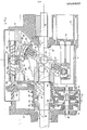
- Figure 1 is a longitudinal cross-section of one embodiment of engine mechanism according to the invention, the piston illustrated being in the bottom dead centre position, and the mechanism being at maximum displacement;
- Figure 2 is a view similar to that of Figure 1, but showing the mechanism at minimum displacement;
- Figure 3 is a transverse cross-section (but not in a true position) of the mechanism of Figure 1, showing the main components of the wabbler plate and stabilizer mechanism;
- Figure 4 shows in longitudinal cross-section a portion of a mechanism similar to that of Figure 1, but incorporating means for independently altering the wabbler carrier angle; and
- . Figure 5 is a view, similar to that of Figure 1, of another embodiment of the invention.
- In none of the figures of the drawings is a cylinder head assembly illustrated. In each case, this may be of conventional design depending of course upon the purpose; i.e. engine or pump, for which the mechanism is to be used.
- In the engine mechanism of Figures 1 to 3, a
crankshaft 2 is mounted inbearings 4 on acrankcase 6 and slidably coupled to an anchor member 8. The anchor member is mounted in radial andthrust bearings 10 on thecrankcase 6. Thecrankshaft 2 supports awabbler carrier 12, pivotally mounted ontrunnion pins 14. Anannular wabbler plate 16 is mounted in thrust andradial bearings 18 on thecarrier 12 and includes a plurality of arms 20 (in this embodiment five) extending radially therefrom. A plurality ofcylinders 22 are arranged around thecrankshaft 2, with their axes parallel thereto, and apiston 24 is reciprocally movable in each cylinder. - At the bottom of each piston is formed a
pocket bore 26 having an open end directed radially inwards towards the crankshaft axis. This bore 26 slidably receives abearing piston 28 to which anarm 20 is coupled by means of a little end bearing on awrist pin 30. As the crankshaft 2(and wabbler carrier 12) rotate, eacharm 20 will describe a lemniscate, (a figure of eight on the surface of a sphere) and this movement is accommodated by the radial freedom afforded by thebearing piston 28 inbore 26, and the tangential freedom afforded by the designed end float onwrist pin 30, best shown in Figure 3. - The
bearing piston 28 andwrist pin 30 assembly has the effect of transferring the engine torque reaction equally to allcylinders 22 frompistons 24 and to crankcase 6, with the exception of the frictional torque generated by the bearing surfaces. To counteract this frictional torque, a stabilizer mechanism is included. This mechanism consists ofball races wabbler plate 16 and aball race carrier 36 mounted on thecrankcase 6 diametrically opposite one of thearms 20. Therace 34 in theball race carrier 36 and the axis of thecrankshaft 2 have a common plane, but therace 34 is concave with respect thereto, defining the arc of a circle with its centre at the intersection of the crankshaft axis and the axis of thetrunnion pins 14. Therace 32 on thewabbler plate 16 defines a similar arc, but because of the rotation of thecrankshaft 2 andwabbler carrier 12, the two races will only be aligned when the engine mechanism is at its top (TDC) or its bottom (BDC) dead centre position. At all other times the races will be mutually inclined and the stabilizer mechanism is completed by aball 38 confined between the tworaces - In order to vary the displacement of the engine mechanism, means are provided for shifting the
crankshaft 2 axially with respect to thecrankcase 6, and for simultaneously altering the angle between thewabbler carrier 12 and the crankshaft axis. The latter alteration changes the stroke of thepistons 24 while the former shifts the oscillatory motion of thepistons 24 such that their respective top dead centre positions are properly located. The shifting means in the embodiment of Figures 1 to 3 operates as follows: - The
main shaft 2 is slidably axially with respect to thecrankcase 6 in thebearings 4 and in the anchor member 8 in a close sliding fit. Thrust bearingrings crankshaft 2 and are rotatably mounted with respect to amember 44 by means ofthrust beings member 44 has "anexternal screw thread 50 which mates with a complementaryinternal screw thread 52 formed in thecrankcase 6. Rotation of themember 44 with respect to thecrankcase 6 shifts thecrankshaft 2 axially within the engine mechanism. Apinion gear 54 is shown for effecting this movement. Manual, electric, pneumatic or hydraulic mechanisms might be used to achieve this, with or without the use of thepinion gear 54. At its other end, to the right as shown in Figures 1 and 2, thecrankshaft 2 is splined to anoutput shaft 36, this splinedcoupling 58 accommodating the axial shift of thecrankshaft 2 without displacing aflange 60 on theoutput shaft 56 for coupling to for example the transmission system of a motor vehicle. - As noted above, the
wabbler carrier 12 is pivotally mounted on thecrankshaft 2 bytrunnion pins 14. For any given axial position of thecrankshaft 2, the angle between thewabbler carrier 12 and the crankshaft axis is fixed by a flexible linkage between thewabbler carrier 12 and the anchor member 8.which prevents relative rotation therebetween. The anchor member 8 carries aconnection 62 to which a twopiece link 64 is pivotally connected at one end. At its other end thelink 64 is pivotally connected to apin 66 mounted on thewabbler carrier 12. An identical linkage will normally be provided on the opposite side of thewabbler carrier 2. When thecrankshaft 2 is shifted axially thelink 64 alters the angle of thewabbler carrier 12 as shown in Figure 3. The dimensions of the linkage will be chosen to provide a suitable displacement characteristic for the mechanism. - It will be appreciated that as the
crankshaft 2 is shifted axially, so must theball race carrier 36 to ensure that the centre of curvature of therace 34 remains at the intersection of thetrunnion pin 14 andcrankshaft 2 axes. To provide this synchronous movement theball race carrier 36 is slidably mounted in thecrankcase 6 onrails 68 and coupled to thecrankshaft 2 by a bearingmember 70. The bearingmember 70 receives therim 72 of abearing ring 74 fixed on thecrankshaft 2. The bearingring 74 is part of a counterweight assembly for preserving dynamic balance of the mechanism, which includes acounterweight 76. Thus, the relative axial positions of thecrankshaft 2, theball race carrier 36 and the counterweight are fixed for all displacement settings of the mechanism. - . With the alteration of the angle of the wabbler carrier the stroke of each
piston 24 is changed, as is the length of the arc required in each of the ball races 32 and 34. This means that, when the races are aligned in the TDC and BDC position, theball 38 will only be confined when the displacement (or stroke) is at a maximum. At other displacements theball 38 could move out of position in theraces races leaf spring 78 extends into eachrace ball 38 towards the centre of the respective race. Thus for the maximum displacement setting shown in Figure 1, eachleaf spring 78 will be fully extended in the TDC or BDC position, while at minimum displacement, as shown in Figure 2, only a minimal flexure (if any) of the leaf springs is required in the TDC or BDC positions to prevent theball 38 from moving to a seizure location in theraces ball race 34 the walls of theraces leaf springs 78 are not required to exert any force. Accordingly, their , stiffness can be very low but the spring rates of diagonally opposed pair of springs must be substantially equal. Thesprings 78 play a secondary role while the engine is in motion at less than maximum displacement, but they become essential when the engine is stationary and the ball races 32 and 34 are aligned. The stiffness of thesprings 78 is a function of the size and weight ofball 38. - In the modification shown in Figure 4, provision is made for altering the angle of the
wabbler carrier 12 without shifting thecrankshaft 2 or alternatively, maintaining the same stroke for thepistons 24 while shifting the crankshaft; i.e., to vary the compression ratio of the mechanism. The anchor member 8 is supported in amember 80 having anexternal screw thread 82 mating with a complementaryinternal screw thread 84 in thecrankcase 6. A rack andpinion gear 86 operable from outside the mechanism is operable to rotate themember 80 to alter its axial location independently of thecrankshaft 2. Other means may be used to shift themember 80 if desired. Axial shifting of the anchor member 8 has the effect of increasing or decreasing the stroke of the mechanism without compensation to the unswept volume (i.e. head volume). For example, if the stroke is slightly increased without changing the position of trunnion pins 14, the unswept volume is decreased by half or additional swept volume, and in combination with the increased swept volume the compression ratio is increased. Decrease of stroke will decrease the compression ratio. - Stabilizer ball races 32 and 34 must be increased in length to accept the additional piston stroke as too must
cylinders 22 accept the additional piston stroke. - In the embodiment of Figure 5, the mounting of the
wabbler carrier 12 andplate 16 on thecrankshaft 2, and the coupling of the wabbler plate to thepistons 24 is substantially the same as in the embodiment of Figures 1 to 3 and will not be described again. In this embodiment though, thecrankshaft 2 is in the form of a cylinder slidably mounted by means ofsplines 55 on anoutput shaft 56 that extends the length of thecrankcase 6 supported inbearings 4 and 4'. The shifting means for the crankshaft comprises a clutchedgearbox 88 driven by agear 90 fixed on theoutput shaft 56, and driving amember 92 axially fixed in relation to thecrankcase 6 and theoutput shaft 56 bybearings member 92 has external screw thread mating with a complementary internal screw thread on thecrankshaft 2. Thegearbox 88 has alayshaft 98 supporting agear 100 in permanent mesh with thegear 90 and aclutch gear 102 movable axially on thelayshaft 98. For any given displacement of the mechanism, the clutch gear l02 is in mesh with a gear l04 on themember 92, the ratio between thegear 100 and thegear 90 being the same as that between theclutch gear 102 and thegear 104, thereby preventing relative rotation between themember 92 and thecrankshaft 2 and fixing their relative axial position. To change the displacement, the clutch gear l02 is shifted so that it disengages from thegear 104 and one of thecone clutches 106 mates respectively with one of the gears l08 and 110, normally rotating freely on thelayshaft 98, which are in permanent mesh withgears member 92. Thegears clutch gear 102 to the right as shown in the figure causes relative rotation of themember 92 in one sense with respect to thecrankshaft 2, and movement to the left in the other. Such relative rotation causes thecrankshaft 2 to shift to the left or the right as shown. - In order to simultaneously alter the angle of the
wabbler carrier 12 to the crankshaft axis, thecarrier 12 has abody 116 fixed thereto with a slot 118 formed therein and extending therefrom in a direction generally perpendicular to the plane of thecarrier 12. Apin 120 fixed with respect to theoutput shaft 56 engages the slot 118, sliding therealong as thecrankshaft 2 is shifted, and forcing the angle to change. The position of the slot 118 and pin 120 will be chosen to produce the desired characteristic, and the slot may be non-linear in certain circumstances. A similar arrangement to that shown and described will normally be provided on the opposite side of thewabbler carrier 12. - The stabilizer mechanism in the embodiment of Figure 5 is similar to that of Figures 1 to 3 in that ball races 32 and 34 are provided on the
wabbler plate 16 and aball race carrier 36 but the means for varying the effective length of the races is different. On thewabbler plate 16, the length ofrace 32 is defined bystops 122 running inguides 124, the stops being continuously urged to the centre of the race by springs'126. Similar means might be employed on theball race carrier 36, but a more definitive device is employed in this example. The effective length of therace 34 is determined bystops 128, but the position of these stops is determined directly by a mechanical coupling to the movement of thecrankshaft 2. As in the embodiment of Figures 1 to 3 theball race carrier 36 moves with the crankshaft, but this movement simultaneously rotates a double threadedshaft 130 through a non-locking screw andnut drive 132.Followers 134 to theshaft 130 drive stops 128 via pins and shapedslots 136 to shorten or lengthen theball race 34 in accordance with the sense of rotation of theshaft 130. - It will be appreciated that many of the features of each embodiment described could be incorporated in the other, but as a rule, that of Figure 5 is more easily incorporated to heavy duty mechanisms, for example large capacity engines, while the first embodiment is better suited to more lightweight structures. Each though enables the displacement to be varied while the mechanism is operating, this being of particular advantage for motor vehicle engines where power requirements change frequently, even during normal use.
- Mechanisms of the invention also have the ability tobe used in tandem, with two or more mechanisms being aligned and coupled to a common output shaft transmission system. In the embodiment of Figure 5, successive mechanisms may be mounted on a
single shaft 56. In the embodiment of Figures 1 to 4, successive crankshafts and output shafts can be slidably coupled. The mechanisms may also be coupled in a horizontally opposed arrangement, withcylinders 22 being aligned with their couterparts in another similar mechanism. In an internal combustion engine comprising two such mechanisms, the ignition system would be incorporated between opposed cylinders, and it will be noted that by adapting the means for altering the angle of the wabbler carrier in one mechanism to be capable of making thatangle 90°, that mechanism may be rendered inoperative, to provide greater reduction in the displacement ratio. - In the embodiments described, each of the adjustments referred to can be made while the mechanism is operated, and for a motor vehicle, even while the vehicle is in motion. Such an application of the invention permits variation of engine capacity and compression ratio according to demand in a manner which can easily be effected between for example town use, motorway driving and acceleration.
Claims (13)
Applications Claiming Priority (4)
| Application Number | Priority Date | Filing Date | Title |
|---|---|---|---|
| GB8008264 | 1980-03-11 | ||
| GB8008264 | 1980-03-11 | ||
| GB8038546 | 1980-12-02 | ||
| GB8038546 | 1980-12-02 |
Publications (3)
| Publication Number | Publication Date |
|---|---|
| EP0035867A2 true EP0035867A2 (en) | 1981-09-16 |
| EP0035867A3 EP0035867A3 (en) | 1982-09-08 |
| EP0035867B1 EP0035867B1 (en) | 1985-07-31 |
Family
ID=26274774
Family Applications (1)
| Application Number | Title | Priority Date | Filing Date |
|---|---|---|---|
| EP19810300895 Expired EP0035867B1 (en) | 1980-03-11 | 1981-03-04 | Wabbler plate engine mechanisms |
Country Status (3)
| Country | Link |
|---|---|
| EP (1) | EP0035867B1 (en) |
| AU (1) | AU545777B2 (en) |
| DE (1) | DE3171533D1 (en) |
Cited By (5)
| Publication number | Priority date | Publication date | Assignee | Title |
|---|---|---|---|---|
| EP0081205A1 (en) * | 1981-12-04 | 1983-06-15 | Dieter Lehmann | Internal combustion wobble plate engine |
| EP0219298A2 (en) * | 1985-10-11 | 1987-04-22 | Sanden Corporation | Variable displacement wobble plate type compressor |
| AU580579B2 (en) * | 1984-02-18 | 1989-01-19 | Ludwig Wenker | Internal-combustion engine |
| WO2003002893A1 (en) * | 2001-06-27 | 2003-01-09 | Stuard Daevys | Swash plate devices |
| ES2937207A1 (en) * | 2021-09-23 | 2023-03-24 | Moran Emiliano Fernandez | AXIAL PISTON PUMP (Machine-translation by Google Translate, not legally binding) |
Families Citing this family (1)
| Publication number | Priority date | Publication date | Assignee | Title |
|---|---|---|---|---|
| US4688439A (en) * | 1984-04-17 | 1987-08-25 | S. V. Engine Co. Pty. Ltd. | Wabble plate engine mechansim |
Citations (20)
| Publication number | Priority date | Publication date | Assignee | Title |
|---|---|---|---|---|
| FR392320A (en) * | 1908-07-15 | 1908-11-24 | Louis Renault | Progressive hydraulic gear change with clutch and brake |
| FR432183A (en) * | 1910-09-28 | 1911-11-30 | Temple Du | Hydraulic speed change |
| DE540055C (en) * | 1923-11-07 | 1931-12-07 | Ludwig Le Bret | Swash gear with variable stroke |
| DE636557C (en) * | 1932-08-23 | 1936-10-12 | Guenther Schneggenburger Dipl | Swash plate transmission |
| GB463543A (en) * | 1935-06-27 | 1937-03-30 | Emil Goelz | Improvements in or relating to hydraulic power transmission gears |
| DE669350C (en) * | 1935-11-16 | 1938-12-23 | Guenther Schneggenburger Dipl | Swash ring gear with rotating swash plate |
| CH218712A (en) * | 1937-10-01 | 1941-12-31 | Variable Speed Gear Limited | Piston machine. |
| US2465638A (en) * | 1945-05-24 | 1949-03-29 | Samuel B Eckert | Stroke varying mechanism for swash plate engines |
| AT175754B (en) * | 1949-06-25 | 1953-08-10 | Heinrich Dr Ing Ebert | Infinitely adjustable liquid piston reduction or transmission gears, especially for machine tools |
| FR57971E (en) * | 1948-01-28 | 1953-09-18 | Applic Mecanique Automobile Et | Hydraulic transmission and speed variator |
| US2718758A (en) * | 1949-07-15 | 1955-09-27 | Borg Warner | Variable ratio hydrostatic transmission |
| DE971177C (en) * | 1949-10-20 | 1958-12-18 | Karl Bauer | Hydrostatic torque converter |
| GB835936A (en) * | 1956-09-25 | 1960-05-25 | Gunnar Axel Wahlmark | Constant velocity universal joint |
| GB906357A (en) * | 1960-01-04 | 1962-09-19 | New York Air Brake Co | Hydraulic engine |
| FR1355385A (en) * | 1963-05-07 | 1964-03-13 | Suzuki Motor Co | Hydrostatic power transmission device |
| US3357209A (en) * | 1965-12-13 | 1967-12-12 | Gen Motors Corp | Universal joint for a hydrostatic transmission |
| GB1204021A (en) * | 1968-04-26 | 1970-09-03 | Johannes Neukirch | Power-branching hydraulic axial piston type transmission |
| DE2107729A1 (en) * | 1971-02-18 | 1972-08-31 | Hestermann G | Swash plate gear |
| DE2206101A1 (en) * | 1972-02-09 | 1973-08-30 | Franz Riedl | CONTINUOUSLY VARIABLE TRANSMISSION WITH A SWASHPLATE-LIKE MOUNTED LINK |
| GB1502425A (en) * | 1975-05-07 | 1978-03-01 | Lucas Industries Ltd | Stroke control apparatus for a variable stroke hydraulic pump |
-
1981
- 1981-03-04 DE DE8181300895T patent/DE3171533D1/en not_active Expired
- 1981-03-04 EP EP19810300895 patent/EP0035867B1/en not_active Expired
- 1981-03-11 AU AU68274/81A patent/AU545777B2/en not_active Ceased
Patent Citations (20)
| Publication number | Priority date | Publication date | Assignee | Title |
|---|---|---|---|---|
| FR392320A (en) * | 1908-07-15 | 1908-11-24 | Louis Renault | Progressive hydraulic gear change with clutch and brake |
| FR432183A (en) * | 1910-09-28 | 1911-11-30 | Temple Du | Hydraulic speed change |
| DE540055C (en) * | 1923-11-07 | 1931-12-07 | Ludwig Le Bret | Swash gear with variable stroke |
| DE636557C (en) * | 1932-08-23 | 1936-10-12 | Guenther Schneggenburger Dipl | Swash plate transmission |
| GB463543A (en) * | 1935-06-27 | 1937-03-30 | Emil Goelz | Improvements in or relating to hydraulic power transmission gears |
| DE669350C (en) * | 1935-11-16 | 1938-12-23 | Guenther Schneggenburger Dipl | Swash ring gear with rotating swash plate |
| CH218712A (en) * | 1937-10-01 | 1941-12-31 | Variable Speed Gear Limited | Piston machine. |
| US2465638A (en) * | 1945-05-24 | 1949-03-29 | Samuel B Eckert | Stroke varying mechanism for swash plate engines |
| FR57971E (en) * | 1948-01-28 | 1953-09-18 | Applic Mecanique Automobile Et | Hydraulic transmission and speed variator |
| AT175754B (en) * | 1949-06-25 | 1953-08-10 | Heinrich Dr Ing Ebert | Infinitely adjustable liquid piston reduction or transmission gears, especially for machine tools |
| US2718758A (en) * | 1949-07-15 | 1955-09-27 | Borg Warner | Variable ratio hydrostatic transmission |
| DE971177C (en) * | 1949-10-20 | 1958-12-18 | Karl Bauer | Hydrostatic torque converter |
| GB835936A (en) * | 1956-09-25 | 1960-05-25 | Gunnar Axel Wahlmark | Constant velocity universal joint |
| GB906357A (en) * | 1960-01-04 | 1962-09-19 | New York Air Brake Co | Hydraulic engine |
| FR1355385A (en) * | 1963-05-07 | 1964-03-13 | Suzuki Motor Co | Hydrostatic power transmission device |
| US3357209A (en) * | 1965-12-13 | 1967-12-12 | Gen Motors Corp | Universal joint for a hydrostatic transmission |
| GB1204021A (en) * | 1968-04-26 | 1970-09-03 | Johannes Neukirch | Power-branching hydraulic axial piston type transmission |
| DE2107729A1 (en) * | 1971-02-18 | 1972-08-31 | Hestermann G | Swash plate gear |
| DE2206101A1 (en) * | 1972-02-09 | 1973-08-30 | Franz Riedl | CONTINUOUSLY VARIABLE TRANSMISSION WITH A SWASHPLATE-LIKE MOUNTED LINK |
| GB1502425A (en) * | 1975-05-07 | 1978-03-01 | Lucas Industries Ltd | Stroke control apparatus for a variable stroke hydraulic pump |
Cited By (6)
| Publication number | Priority date | Publication date | Assignee | Title |
|---|---|---|---|---|
| EP0081205A1 (en) * | 1981-12-04 | 1983-06-15 | Dieter Lehmann | Internal combustion wobble plate engine |
| AU580579B2 (en) * | 1984-02-18 | 1989-01-19 | Ludwig Wenker | Internal-combustion engine |
| EP0219298A2 (en) * | 1985-10-11 | 1987-04-22 | Sanden Corporation | Variable displacement wobble plate type compressor |
| EP0219298A3 (en) * | 1985-10-11 | 1988-01-27 | Sanden Corporation | Variable displacement wobble plate type compressor |
| WO2003002893A1 (en) * | 2001-06-27 | 2003-01-09 | Stuard Daevys | Swash plate devices |
| ES2937207A1 (en) * | 2021-09-23 | 2023-03-24 | Moran Emiliano Fernandez | AXIAL PISTON PUMP (Machine-translation by Google Translate, not legally binding) |
Also Published As
| Publication number | Publication date |
|---|---|
| EP0035867A3 (en) | 1982-09-08 |
| AU545777B2 (en) | 1985-08-01 |
| AU6827481A (en) | 1981-09-17 |
| EP0035867B1 (en) | 1985-07-31 |
| DE3171533D1 (en) | 1985-09-05 |
Similar Documents
| Publication | Publication Date | Title |
|---|---|---|
| US4433596A (en) | Wabbler plate engine mechanisms | |
| US8827856B1 (en) | Infinitely variable transmission with an IVT stator controlling assembly | |
| US4077269A (en) | Variable displacement and/or variable compression ratio piston engine | |
| US5113809A (en) | Axial cylinder internal combustion engine having variable displacement | |
| EP1992806B1 (en) | Internal combustion engine employing variable compression ratio mechanism | |
| US6460450B1 (en) | Piston engine balancing | |
| US20110155106A1 (en) | Internal combustion engine with variable compression ratio | |
| US5092293A (en) | Crankshaft-systems for split environmental engines and multi-split environmental engines | |
| RU2296234C1 (en) | Crank mechanism | |
| US20010041642A1 (en) | Toroidal type continuous variable speed transmission | |
| AU2007209223A1 (en) | Crankshaft for a variable compression ratio engine | |
| EP0035867B1 (en) | Wabbler plate engine mechanisms | |
| US4270400A (en) | Continuously variable traction drive transmission | |
| US5189927A (en) | Variable ratio drive transmission | |
| CN101634354B (en) | Crank circular slide block mechanism as well as internal-combustion engine and compressor thereof | |
| US5394853A (en) | Supercharging device for an internal combustion engine | |
| US7213545B2 (en) | Reciprocating engine | |
| EP0164845A2 (en) | Wabble plate engine mechanism | |
| CA1209822A (en) | Wabbler plate engine mechanisms | |
| AU759540B2 (en) | Electronically controlled dampener for hydrostatic transmission | |
| US4565103A (en) | Connecting rod bearings for a volumetric piston chamber machine | |
| US9447727B2 (en) | Variable displacement engine | |
| US6016719A (en) | Continuously variable reciprocating transmission device | |
| CN114198213A (en) | Variable displacement and variable compression ratio engine integrated with continuously variable transmission | |
| WO1988010382A1 (en) | Mechanical transmission |
Legal Events
| Date | Code | Title | Description |
|---|---|---|---|
| PUAI | Public reference made under article 153(3) epc to a published international application that has entered the european phase |
Free format text: ORIGINAL CODE: 0009012 |
|
| AK | Designated contracting states |
Designated state(s): DE FR GB IT |
|
| PUAL | Search report despatched |
Free format text: ORIGINAL CODE: 0009013 |
|
| AK | Designated contracting states |
Designated state(s): DE FR GB IT |
|
| 17P | Request for examination filed |
Effective date: 19830210 |
|
| RAP1 | Party data changed (applicant data changed or rights of an application transferred) |
Owner name: SCALZO, JOSEPH |
|
| ITF | It: translation for a ep patent filed |
Owner name: MODIANO & ASSOCIATI S.R.L. |
|
| GRAA | (expected) grant |
Free format text: ORIGINAL CODE: 0009210 |
|
| AK | Designated contracting states |
Designated state(s): DE FR GB IT |
|
| REF | Corresponds to: |
Ref document number: 3171533 Country of ref document: DE Date of ref document: 19850905 |
|
| ET | Fr: translation filed | ||
| PLBE | No opposition filed within time limit |
Free format text: ORIGINAL CODE: 0009261 |
|
| STAA | Information on the status of an ep patent application or granted ep patent |
Free format text: STATUS: NO OPPOSITION FILED WITHIN TIME LIMIT |
|
| 26N | No opposition filed | ||
| PG25 | Lapsed in a contracting state [announced via postgrant information from national office to epo] |
Ref country code: GB Effective date: 19890304 |
|
| GBPC | Gb: european patent ceased through non-payment of renewal fee | ||
| PG25 | Lapsed in a contracting state [announced via postgrant information from national office to epo] |
Ref country code: FR Free format text: LAPSE BECAUSE OF NON-PAYMENT OF DUE FEES Effective date: 19891130 |
|
| PG25 | Lapsed in a contracting state [announced via postgrant information from national office to epo] |
Ref country code: DE Effective date: 19891201 |
|
| REG | Reference to a national code |
Ref country code: FR Ref legal event code: ST |