EP0035552B1 - Apparatus for advancing a record medium - Google Patents
Apparatus for advancing a record medium Download PDFInfo
- Publication number
- EP0035552B1 EP0035552B1 EP80901843A EP80901843A EP0035552B1 EP 0035552 B1 EP0035552 B1 EP 0035552B1 EP 80901843 A EP80901843 A EP 80901843A EP 80901843 A EP80901843 A EP 80901843A EP 0035552 B1 EP0035552 B1 EP 0035552B1
- Authority
- EP
- European Patent Office
- Prior art keywords
- driving
- driving unit
- rotatable member
- coupling means
- rotatable
- Prior art date
- Legal status (The legal status is an assumption and is not a legal conclusion. Google has not performed a legal analysis and makes no representation as to the accuracy of the status listed.)
- Expired
Links
- 230000008878 coupling Effects 0.000 claims abstract description 29
- 238000010168 coupling process Methods 0.000 claims abstract description 29
- 238000005859 coupling reaction Methods 0.000 claims abstract description 29
- 230000002093 peripheral effect Effects 0.000 claims description 6
- 239000000463 material Substances 0.000 description 2
- 229920004943 Delrin® Polymers 0.000 description 1
- 238000001746 injection moulding Methods 0.000 description 1
- 238000004519 manufacturing process Methods 0.000 description 1
- 230000013011 mating Effects 0.000 description 1
- 230000000717 retained effect Effects 0.000 description 1
Images


Classifications
-
- B—PERFORMING OPERATIONS; TRANSPORTING
- B41—PRINTING; LINING MACHINES; TYPEWRITERS; STAMPS
- B41J—TYPEWRITERS; SELECTIVE PRINTING MECHANISMS, i.e. MECHANISMS PRINTING OTHERWISE THAN FROM A FORME; CORRECTION OF TYPOGRAPHICAL ERRORS
- B41J11/00—Devices or arrangements of selective printing mechanisms, e.g. ink-jet printers or thermal printers, for supporting or handling copy material in sheet or web form
- B41J11/36—Blanking or long feeds; Feeding to a particular line, e.g. by rotation of platen or feed roller
-
- B—PERFORMING OPERATIONS; TRANSPORTING
- B41—PRINTING; LINING MACHINES; TYPEWRITERS; STAMPS
- B41J—TYPEWRITERS; SELECTIVE PRINTING MECHANISMS, i.e. MECHANISMS PRINTING OTHERWISE THAN FROM A FORME; CORRECTION OF TYPOGRAPHICAL ERRORS
- B41J19/00—Character- or line-spacing mechanisms
- B41J19/76—Line-spacing mechanisms
- B41J19/78—Positive-feed mechanisms
Definitions
- This invention relates to an apparatus for advancing a record medium in a printing machine.
- a platen and pinch rollers are utilized to advance a record medium with regard to the associated print head. As each line of printing is completed, the platen is incrementally rotated to advance the record medium thereon. At certain times, it is desirable to fast-feed the record medium past the print head without any printing taking place.
- an apparatus for advancing a record medium including a rotatable member connected to a record medium advancing member for rotation therewith, characterized in that said rotatable member has engagement surfaces and a driving surface thereon; and further characterized by a rotatable driving unit having at least one driving member thereon to engage said engagement surfaces and thereby incrementally rotate said rotatable member as said driving unit is rotated; and a coupling means movable between first and second positions whereby said coupling means is operatively disconnected from said driving unit and said rotatable member when in said first position and whereby said coupling means when in said second position is effective to disconnect said at least one driving member from said engagement surfaces and to operatively connect said driving unit with said driving surface to continuously rotate said rotatable member as said driving unit is rotated.
- the apparatus has means for resiliently urging said driving unit into contact with said engagement surfaces, said rotatable member being capable of being manually rotated when said driving unit is not rotated.
- Fig. 1 is a general perspective view, in exploded form, of a preferred embodiment of the apparatus of this invention which is designated generally as 10.
- the apparatus 10 generally includes a rotatable member 12, a rotatable driving unit 14, and a coupling means 1 6 which enables the apparatus to be operated in different modes as will be described hereinafter.
- the rotatable member 12 (Fig. 1) rotates the platen 18 by having the shaft 20 supporting the platen secured to the hub 22 by a pin 24.
- the shaft 20 is supported in a conventional frame 26 shown only diagrammatically in Fig. 1.
- the platen 18 and the rotatable member 12 are rotatably mounted in the frame 26 and restrained from axial movement relative to the frame 26 by suitable "C" washers 28 which may be anchored via the frame 26.
- Suitable pinch rollers such as 30 are used to resiliently bias a record medium 32 against the platen 18 causing the record medium 32 to be fed in the direction of arrow 34 whenever the rotatable member 12 is rotated in the direction of arrow 36.
- a print head 38 is conventionally traversed across a line of printing on the record medium 32 by a continuous cam 40 on a barrel cam 42; conventional cam follower linkage shown as dashed line 43 interconnects the barrel cam 42 with the print head 38 for this purpose.
- the rotatable member 12 (Figs. 1, 5, 6) has a plurality of engagement surface or teeth 44 on the periphery thereof as shown.
- the rotatable member 12 is made of a plastic material such as Delrin (RTM) which is manufactured by DuPont, and which material may be conventionally formed, as by injection moulding, for example.
- the rotatable member 12 also has a continuous driving surface 45 which is generally conical in shape as is best shown in Fig. 6. In the embodiment described, the surface 45 lies at an angle of 15 degrees with respect to a vertical line in Fig. 6.
- the rotatable driving unit 14 (Fig. 1-4) has an inner cylindrical wall 46 and a flat surface 48 forming a circular edge 50 therebetween as is best shown in Fig. 1.
- the driving unit 14 also has a circular base 52 having a square hole 54 therein.
- the hole 54 extends through an extension 56 on the unit 14, and the square end 58 of a driving shaft 60 is inserted in the square hole 54 of the driving unit 14 to form a driving connection therebetween.
- the square end 58 of the shaft 60 has an enlarged area 62 to provide an abutment area for a spring 64 which is positioned between the extension 56 and the enlarged area 62 to resiliently bias the unit 14 into engagement with the rotatable member 12 as will be described later herein.
- the driving unit 14 is axially movable on the square end 58 of the shaft 60.
- the shaft 60 is rotatably supported in a bearing 66 and is rotatably driven by any convenient driving member such as a bevel gear 68.
- the bearing 66 has expandable fingers 67 thereon which engage a conventional mating member (not shown) which is part of the frame 26 to provide a fixed center of rotation for the driving unit 14.
- the bevel gear 68 is driven by an identical second bevel gear 70 which is fixed to a shaft 72 of the barrel cam 42 which in turn is driven by any conventional drive (not shown).
- the rotatable driving unit 14 (Figs. 1-4) has two driving members or lugs 74 and 76 located on top surface 48 thereof.
- the function of these lugs 74 and 76 is to coact with the teeth 44 on the rotatable member 12 and thereby incrementally rotate the member 12 as the driving unit 14 is rotated.
- lugs 74 and 76 are utilized to index the platen 18 to present a new line on the record medium 32 for printing each time the print head 38 reaches a limit of travel in opposed directions along the platen 18. The operation of the lugs 74 and 76 will be described in detail hereinafter.
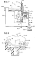
- the coupling means 16 alluded to earlier herein (Figs. 1 and 7) includes an "S"-shaped level 78 with one end of a rod 80 fixed thereto as shown.
- the lever 78 has two elongated slots 82 and 84 therein through which screws 86 and 88 pass to slidably retain the lever 78 to the frame 26 as shown in Fig. 7.
- a solenoid 90 secured to the frame 26 by a bracket 92, is used to pull the lever 78 downwardly as viewed in Figs. 1 and 7 when the solenoid is energized.
- the coupling means 16 (Figs. 1 and 7) also includes a coupling member 94 having a first cylindrical portion 96 and a second cylindrical portion 98 which have a common axis of rotation.
- the cylindrical portions 98 and 96 have diameters of approximately 25 millimeters and 10 millimeters, respectively, in the embodiment described.
- the coupling member 94 is rotatably mounted on the rod 80 and retained thereon by a "C" washer (not shown) which is inserted in the annular groove 100.
- the coupling member 94 has an "0" ring 102 located in a matching annular recess (not shown) on the first cylindrical portion 96 to form a first peripheral driving surface and a second "0" ring 104 similarly mounted on the second cylindrical portion 98 to form a second peripheral driving surface.
- the driving unit 14 When the apparatus 10 is operated in the incremental mode, the driving unit 14 is rotated in timed relationship with the print head 38 (Fig. 1) so that when the print head 38 reaches a limit of travel in one direction, one of the lugs 74 and 76 engages a tooth 44 on the rotatable member 12 as will be later described herein.
- the coupling means 16 When the apparatus 10 is operated in the incremental mode, the coupling means 16 is in a first position in which the coupling member 94 is positioned closer to the hub 22 than is shown in Fig. 7 and in which the "0" ring 104 is out of engagement with the driving surface 45.
- the leading edge 108 encounters a tooth face marked 44a in Fig. 8.
- the rotational axis 110 of the driving unit 14 is laterally offset from an imaginary plane including the rotating axis 112 of the rotatable member 12 to enable only one lug 74 and 76 to engage the rotatable member 12 at any one time.
- a portion 114 (having the profile shown in Fig. 4) of the driving lug 74, which portion 114 is offset at an angle toward the axis of rotation 110 of the unit 14, engages the face 44A (Fig.
- each of the driving lugs 74 and 76 as viewed in Fig. 8 is equal to the length of a side of a tooth 44.
- the included angle at the apex of each tooth 44 is ninety degrees, and in the embodiment described, the outer diameter of the rotatable member 12 is about 57 millimeters with 94 teeth being formed on the periphery thereof.
- the outer diameter of the driving unit 14 shown in Fig. 8 is approximately 44 millimeters as measured along the associated section line 8-8 shown in Fig. 3.
- the solenoid 90 be energized to pull the lever 78 downwardly (as viewed in Fig. 7) to move the coupling means 16 to the second position shown therein.
- the coupling means 16 is moved from the first position to the second position (shown in Fig. 7)
- the free end of rod 80 engages the base 52 of the driving unit 14 causing it to be moved downwardly against the bias of spring 64, thereby preventing the driving lugs 74 and 76 from engaging the rotatable member 12 as the driving unit 14 is rotated.
- the coupling member 94 moves downwardly as viewed in Fig.
- the "0" ring 104 thereon engages the driving surface 45 on the rotatable member 12, and because the "0" ring 102 is in driving contact with the inner cylindrical wall 46 of the driving unit 14, a driving connection is effected between the driving unit 14 and the rotatable member 12 causing it to rotate in the direction of arrow 36 (Fig. 1) at a fast and continuous rate or expressed differently it means to fast-feed the record medium 32.
- the solenoid 90 is de-energized, permitting the spring 64 (Fig. 1) to move the coupling means 16 to the first position in which the "O" ring 104 is out of contact with the driving surface 45 on the rotatable member 12.
- the driving unit 14 may be rotated in either direction; however, it is preferable to rotate it in the direction of arrow 106 (Fig. 1) for more positive driving of the rotatable member 12.
- the apparatus can also be operated manually.
- the driving unit 14 When so operated, the driving unit 14 is not being rotated; consequently, the rotatable member 12 simply can be rotated manually.
- the circular edge 50 of the driving unit 14 engages adjacent ones of the teeth 44 as shown in Fig. 8 to normally restrain the rotatable member 12 from rotating.
- the driving unit 14 is pushed downwardly thereby (as viewed in Fig. 8) against the bias of the spring 64, and the circular edge 50 returns to the position shown in Fig. 8 to engage the next succeeding adjacent teeth 44 to operate in detent- ing fashion.
Landscapes
- Transmission Devices (AREA)
- Handling Of Sheets (AREA)
- Character Spaces And Line Spaces In Printers (AREA)
Abstract
Description
- This invention relates to an apparatus for advancing a record medium in a printing machine.
- In certain printing or typing operations, for example, a platen and pinch rollers are utilized to advance a record medium with regard to the associated print head. As each line of printing is completed, the platen is incrementally rotated to advance the record medium thereon. At certain times, it is desirable to fast-feed the record medium past the print head without any printing taking place.
- Some of the prior art apparatus for performing incremental and fast-feed of the record medium are extremely complex in design and expensive to manufacture.
- It is an object of the invention to provide a simple, low-cost, record medium advancing apparatus which can be operated in the incremental and fast-feed modes.
- Thus, according to the invention, there is provided an apparatus for advancing a record medium including a rotatable member connected to a record medium advancing member for rotation therewith, characterized in that said rotatable member has engagement surfaces and a driving surface thereon; and further characterized by a rotatable driving unit having at least one driving member thereon to engage said engagement surfaces and thereby incrementally rotate said rotatable member as said driving unit is rotated; and a coupling means movable between first and second positions whereby said coupling means is operatively disconnected from said driving unit and said rotatable member when in said first position and whereby said coupling means when in said second position is effective to disconnect said at least one driving member from said engagement surfaces and to operatively connect said driving unit with said driving surface to continuously rotate said rotatable member as said driving unit is rotated.
- Preferably, the apparatus has means for resiliently urging said driving unit into contact with said engagement surfaces, said rotatable member being capable of being manually rotated when said driving unit is not rotated.
- One embodiment of the invention will now be described, by way of example, with reference to the accompanying drawings, in which:
- Fig. 1 is a general perspective view, in exploded form, showing a preferred embodiment of the record medium advancing apparatus of the invention, including generally, a rotatable member, a rotatable driving unit and a coupling means;
- Fig. 2 is a side view of a portion of the rotatable driving unit shown in Fig. 1;
- Fig. 3 is a plan view of the portion of the driving unit shown in Fig. 2;
- Fig. 4 is an enlarged view taken along the line 4-4 of Fig. 3 showing additional details of a driving member on the driving unit;
- Fig. 5 is a side view of the rotatable member shown in Fig. 1;
- Fig. 6 is a cross-sectional view taken along the line 6-6 of Fig. 5;
- Fig. 7 is an assembled view, in elevation and partly in cross section, of a portion of the elements included in Fig. 1; and
- Fig. 8 is a cross-sectional view of the driving unit which view is taken along line 8-8 of Fig. 3 to show its relationship to a portion of the rotatable member; the elements shown herein are exaggerated in size to facilitate a showing thereof.
- Fig. 1 is a general perspective view, in exploded form, of a preferred embodiment of the apparatus of this invention which is designated generally as 10. The
apparatus 10 generally includes arotatable member 12, arotatable driving unit 14, and a coupling means 1 6 which enables the apparatus to be operated in different modes as will be described hereinafter. - The rotatable member 12 (Fig. 1) rotates the
platen 18 by having theshaft 20 supporting the platen secured to thehub 22 by apin 24. Theshaft 20 is supported in aconventional frame 26 shown only diagrammatically in Fig. 1. Theplaten 18 and therotatable member 12 are rotatably mounted in theframe 26 and restrained from axial movement relative to theframe 26 by suitable "C"washers 28 which may be anchored via theframe 26. Suitable pinch rollers such as 30 are used to resiliently bias arecord medium 32 against theplaten 18 causing therecord medium 32 to be fed in the direction ofarrow 34 whenever therotatable member 12 is rotated in the direction ofarrow 36. Aprint head 38 is conventionally traversed across a line of printing on therecord medium 32 by acontinuous cam 40 on abarrel cam 42; conventional cam follower linkage shown as dashedline 43 interconnects thebarrel cam 42 with theprint head 38 for this purpose. - The rotatable member 12 (Figs. 1, 5, 6) has a plurality of engagement surface or
teeth 44 on the periphery thereof as shown. In the embodiment described, therotatable member 12 is made of a plastic material such as Delrin (RTM) which is manufactured by DuPont, and which material may be conventionally formed, as by injection moulding, for example. Therotatable member 12 also has acontinuous driving surface 45 which is generally conical in shape as is best shown in Fig. 6. In the embodiment described, thesurface 45 lies at an angle of 15 degrees with respect to a vertical line in Fig. 6. - The rotatable driving unit 14 (Fig. 1-4) has an inner
cylindrical wall 46 and aflat surface 48 forming acircular edge 50 therebetween as is best shown in Fig. 1. The drivingunit 14 also has acircular base 52 having asquare hole 54 therein. Thehole 54 extends through anextension 56 on theunit 14, and thesquare end 58 of a drivingshaft 60 is inserted in thesquare hole 54 of the drivingunit 14 to form a driving connection therebetween. Thesquare end 58 of theshaft 60 has anenlarged area 62 to provide an abutment area for aspring 64 which is positioned between theextension 56 and theenlarged area 62 to resiliently bias theunit 14 into engagement with therotatable member 12 as will be described later herein. The drivingunit 14 is axially movable on thesquare end 58 of theshaft 60. Theshaft 60 is rotatably supported in abearing 66 and is rotatably driven by any convenient driving member such as abevel gear 68. Thebearing 66 hasexpandable fingers 67 thereon which engage a conventional mating member (not shown) which is part of theframe 26 to provide a fixed center of rotation for the drivingunit 14. In the embodiment described, thebevel gear 68 is driven by an identicalsecond bevel gear 70 which is fixed to ashaft 72 of thebarrel cam 42 which in turn is driven by any conventional drive (not shown). - The rotatable driving unit 14 (Figs. 1-4) has two driving members or lugs 74 and 76 located on
top surface 48 thereof. The function of theselugs teeth 44 on therotatable member 12 and thereby incrementally rotate themember 12 as the drivingunit 14 is rotated. When theprint head 38 is used for bi-directional printing, for example, lugs 74 and 76 are utilized to index theplaten 18 to present a new line on therecord medium 32 for printing each time theprint head 38 reaches a limit of travel in opposed directions along theplaten 18. The operation of thelugs - The coupling means 16 alluded to earlier herein (Figs. 1 and 7) includes an "S"-shaped
level 78 with one end of arod 80 fixed thereto as shown. Thelever 78 has twoelongated slots lever 78 to theframe 26 as shown in Fig. 7. Asolenoid 90, secured to theframe 26 by abracket 92, is used to pull thelever 78 downwardly as viewed in Figs. 1 and 7 when the solenoid is energized. - The coupling means 16 (Figs. 1 and 7) also includes a
coupling member 94 having a firstcylindrical portion 96 and a secondcylindrical portion 98 which have a common axis of rotation. Thecylindrical portions coupling member 94 is rotatably mounted on therod 80 and retained thereon by a "C" washer (not shown) which is inserted in theannular groove 100. Thecoupling member 94 has an "0"ring 102 located in a matching annular recess (not shown) on the firstcylindrical portion 96 to form a first peripheral driving surface and a second "0"ring 104 similarly mounted on the secondcylindrical portion 98 to form a second peripheral driving surface. - When the
apparatus 10 is operated in the incremental mode, the drivingunit 14 is rotated in timed relationship with the print head 38 (Fig. 1) so that when theprint head 38 reaches a limit of travel in one direction, one of thelugs tooth 44 on therotatable member 12 as will be later described herein. When theapparatus 10 is operated in the incremental mode, the coupling means 16 is in a first position in which thecoupling member 94 is positioned closer to thehub 22 than is shown in Fig. 7 and in which the "0"ring 104 is out of engagement with the drivingsurface 45. - As the driving
unit 14 is rotated in the direction of arrow 106 (Figs. 1, 3) the leading edge 108 (which is chamfered) encounters a tooth face marked 44a in Fig. 8. As seen in Fig. 8, therotational axis 110 of the drivingunit 14 is laterally offset from an imaginary plane including therotating axis 112 of therotatable member 12 to enable only onelug rotatable member 12 at any one time. As the drivingunit 14 rotates, a portion 114 (having the profile shown in Fig. 4) of the drivinglug 74, whichportion 114 is offset at an angle toward the axis ofrotation 110 of theunit 14, engages theface 44A (Fig. 8) and shifts it toward theaxis 110, causing therotatable member 12 to rotate in the direction of arrow 36 (Figs. 1, 8). As therotatable member 12 begins to rotate, the drivingunit 14 is pushed downwardly (as viewed in Fig. 1) against the bias ofspring 64. When the offsetportion 114 clears atooth 44, therotatable member 12 will have been rotated or incremented one tooth position and thecircular edge 50 of the drivingunit 14 will rise to again engage the next successive ones of theteeth 44 to thereby restrain therotatable member 12 from rotation until the next drivinglug 76 encounters thenext tooth 44 on therotatable member 12. The offsetportion 114 of drivinglug 74 as measured at D in Fig. 4 has a length of about 6 millimeters in the embodiment described and the width of theteeth 44 on therotatable member 12 is about 3 millimeters. The height of each of the driving lugs 74 and 76 as viewed in Fig. 8 is equal to the length of a side of atooth 44. The included angle at the apex of eachtooth 44 is ninety degrees, and in the embodiment described, the outer diameter of therotatable member 12 is about 57 millimeters with 94 teeth being formed on the periphery thereof. The outer diameter of the drivingunit 14 shown in Fig. 8 is approximately 44 millimeters as measured along the associated section line 8-8 shown in Fig. 3. - When the
apparatus 10 is to be operated in the fast-feed mode, it is necessary that thesolenoid 90 be energized to pull thelever 78 downwardly (as viewed in Fig. 7) to move the coupling means 16 to the second position shown therein. As the coupling means 16 is moved from the first position to the second position (shown in Fig. 7), the free end ofrod 80 engages thebase 52 of thedriving unit 14 causing it to be moved downwardly against the bias ofspring 64, thereby preventing thedriving lugs rotatable member 12 as thedriving unit 14 is rotated. As thecoupling member 94 moves downwardly as viewed in Fig. 7, the "0"ring 104 thereon engages the drivingsurface 45 on therotatable member 12, and because the "0"ring 102 is in driving contact with the innercylindrical wall 46 of the drivingunit 14, a driving connection is effected between the drivingunit 14 and therotatable member 12 causing it to rotate in the direction of arrow 36 (Fig. 1) at a fast and continuous rate or expressed differently it means to fast-feed therecord medium 32. When it is desired to end the fast-feed of therecord medium 32, thesolenoid 90 is de-energized, permitting the spring 64 (Fig. 1) to move the coupling means 16 to the first position in which the "O"ring 104 is out of contact with the drivingsurface 45 on therotatable member 12. The drivingunit 14 may be rotated in either direction; however, it is preferable to rotate it in the direction of arrow 106 (Fig. 1) for more positive driving of therotatable member 12. - As stated earlier, the apparatus can also be operated manually. When so operated, the driving
unit 14 is not being rotated; consequently, therotatable member 12 simply can be rotated manually. Thecircular edge 50 of the drivingunit 14 engages adjacent ones of theteeth 44 as shown in Fig. 8 to normally restrain therotatable member 12 from rotating. When therotatable member 12 is manually rotated, the drivingunit 14 is pushed downwardly thereby (as viewed in Fig. 8) against the bias of thespring 64, and thecircular edge 50 returns to the position shown in Fig. 8 to engage the next succeedingadjacent teeth 44 to operate in detent- ing fashion.
Claims (10)
Applications Claiming Priority (2)
| Application Number | Priority Date | Filing Date | Title |
|---|---|---|---|
| US76055 | 1979-09-17 | ||
| US06/076,055 US4279524A (en) | 1979-09-17 | 1979-09-17 | Apparatus for advancing a record medium |
Publications (3)
| Publication Number | Publication Date |
|---|---|
| EP0035552A1 EP0035552A1 (en) | 1981-09-16 |
| EP0035552A4 EP0035552A4 (en) | 1982-07-12 |
| EP0035552B1 true EP0035552B1 (en) | 1984-06-20 |
Family
ID=22129661
Family Applications (1)
| Application Number | Title | Priority Date | Filing Date |
|---|---|---|---|
| EP80901843A Expired EP0035552B1 (en) | 1979-09-17 | 1981-03-23 | Apparatus for advancing a record medium |
Country Status (5)
| Country | Link |
|---|---|
| US (1) | US4279524A (en) |
| EP (1) | EP0035552B1 (en) |
| JP (1) | JPS56501120A (en) |
| DE (1) | DE3068311D1 (en) |
| WO (1) | WO1981000694A1 (en) |
Families Citing this family (1)
| Publication number | Priority date | Publication date | Assignee | Title |
|---|---|---|---|---|
| IT1162944B (en) * | 1983-09-29 | 1987-04-01 | Olivetti & Co Spa | MACHINE OF INTERLINEA FOR WRITING MACHINE |
Family Cites Families (9)
| Publication number | Priority date | Publication date | Assignee | Title |
|---|---|---|---|---|
| US687496A (en) * | 1901-07-30 | 1901-11-26 | Union Typewriter Co | Type-writing machine. |
| US965346A (en) * | 1909-07-22 | 1910-07-26 | Underwood Typewriter Co | Type-writing machine. |
| US1985959A (en) * | 1930-03-19 | 1935-01-01 | Underwood Elliott Fisher Co | Typewriting machine |
| US2917153A (en) * | 1956-10-19 | 1959-12-15 | Information Systems Inc | Line space programming apparatus for an electric typewriter |
| US3272303A (en) * | 1965-02-10 | 1966-09-13 | Pohl Carl | Typewriter control apparatus |
| US3820646A (en) * | 1970-05-19 | 1974-06-28 | Olivetti & Co Spa | Programmed vertical tabulating device for typewriter |
| US3856128A (en) * | 1973-09-20 | 1974-12-24 | Sperry Rand Corp | Printer variable form length controller |
| CH570877A5 (en) * | 1973-11-22 | 1975-12-31 | Paillard Sa | |
| US4013159A (en) * | 1974-05-30 | 1977-03-22 | Copal Company Limited | Printer having a limited movement platen and/or printing head and independent supports therefor |
-
1979
- 1979-09-17 US US06/076,055 patent/US4279524A/en not_active Expired - Lifetime
-
1980
- 1980-09-10 DE DE8080901843T patent/DE3068311D1/en not_active Expired
- 1980-09-10 JP JP50213280A patent/JPS56501120A/ja active Pending
- 1980-09-10 WO PCT/US1980/001183 patent/WO1981000694A1/en not_active Ceased
-
1981
- 1981-03-23 EP EP80901843A patent/EP0035552B1/en not_active Expired
Also Published As
| Publication number | Publication date |
|---|---|
| DE3068311D1 (en) | 1984-07-26 |
| EP0035552A4 (en) | 1982-07-12 |
| EP0035552A1 (en) | 1981-09-16 |
| JPS56501120A (en) | 1981-08-13 |
| US4279524A (en) | 1981-07-21 |
| WO1981000694A1 (en) | 1981-03-19 |
Similar Documents
| Publication | Publication Date | Title |
|---|---|---|
| JP2994014B2 (en) | Paper alignment system | |
| US4165190A (en) | Serial printing apparatus | |
| US4090410A (en) | Paper feeding mechanism | |
| US3977262A (en) | Drive mechanism for a carriage | |
| EP0191176B1 (en) | Single stepping motor ribbon and correction tape feed and lift system | |
| EP0150100B1 (en) | A ribbon lifting device for a printer | |
| JPS6151997B2 (en) | ||
| US4533267A (en) | Ribbon driving mechanism for typewriter | |
| EP0035552B1 (en) | Apparatus for advancing a record medium | |
| GB2126725A (en) | Pen changer for use in an x-y plotter | |
| US4126400A (en) | Serial printing apparatus | |
| US4335970A (en) | Type wheel for serial printing apparatus | |
| US3625331A (en) | Type head positioning apparatus | |
| US4022313A (en) | Ribbon lifting mechanism | |
| JPS6035277B2 (en) | Printing mechanism for consecutive number printing | |
| US4436192A (en) | Ribbon drive clutch | |
| US4589788A (en) | Mechanism for raising and transporting of print and correction ribbons | |
| CA1083884A (en) | Cam drive for matrix print heads and the like | |
| US4128346A (en) | Daisy type print wheel apparatus | |
| US5505131A (en) | Ink fountain apparatus | |
| JPH0114029B2 (en) | ||
| EP0528794A1 (en) | DEVICE FOR GENERATING AND UNCOUPLING DIFFERENT MOVEMENTS IN CLEANING AND SEALING STATIONS IN INK PRINTING DEVICES. | |
| US4265555A (en) | Dual pitch carriage drive mechanism | |
| JPS5851833B2 (en) | platen displacement device | |
| US4832517A (en) | Printing apparatus with a type wheel |
Legal Events
| Date | Code | Title | Description |
|---|---|---|---|
| PUAI | Public reference made under article 153(3) epc to a published international application that has entered the european phase |
Free format text: ORIGINAL CODE: 0009012 |
|
| AK | Designated contracting states |
Designated state(s): DE FR GB |
|
| 17P | Request for examination filed |
Effective date: 19810805 |
|
| DET | De: translation of patent claims | ||
| GRAA | (expected) grant |
Free format text: ORIGINAL CODE: 0009210 |
|
| AK | Designated contracting states |
Designated state(s): DE FR GB |
|
| PGFP | Annual fee paid to national office [announced via postgrant information from national office to epo] |
Ref country code: FR Payment date: 19840711 Year of fee payment: 5 |
|
| REF | Corresponds to: |
Ref document number: 3068311 Country of ref document: DE Date of ref document: 19840726 |
|
| PGFP | Annual fee paid to national office [announced via postgrant information from national office to epo] |
Ref country code: DE Payment date: 19841004 Year of fee payment: 5 |
|
| ET | Fr: translation filed | ||
| PLBE | No opposition filed within time limit |
Free format text: ORIGINAL CODE: 0009261 |
|
| STAA | Information on the status of an ep patent application or granted ep patent |
Free format text: STATUS: NO OPPOSITION FILED WITHIN TIME LIMIT |
|
| 26N | No opposition filed | ||
| PG25 | Lapsed in a contracting state [announced via postgrant information from national office to epo] |
Ref country code: GB Effective date: 19880910 |
|
| PG25 | Lapsed in a contracting state [announced via postgrant information from national office to epo] |
Ref country code: FR Free format text: LAPSE BECAUSE OF NON-PAYMENT OF DUE FEES Effective date: 19890531 |
|
| GBPC | Gb: european patent ceased through non-payment of renewal fee | ||
| PG25 | Lapsed in a contracting state [announced via postgrant information from national office to epo] |
Ref country code: DE Effective date: 19890601 |
|
| REG | Reference to a national code |
Ref country code: FR Ref legal event code: ST |