EP0035441B1 - Speiseleitungsgerät für Doppler-VOR-Radionavigationssystem und seine Verwendung - Google Patents
Speiseleitungsgerät für Doppler-VOR-Radionavigationssystem und seine Verwendung Download PDFInfo
- Publication number
- EP0035441B1 EP0035441B1 EP81400288A EP81400288A EP0035441B1 EP 0035441 B1 EP0035441 B1 EP 0035441B1 EP 81400288 A EP81400288 A EP 81400288A EP 81400288 A EP81400288 A EP 81400288A EP 0035441 B1 EP0035441 B1 EP 0035441B1
- Authority
- EP
- European Patent Office
- Prior art keywords
- antennas
- signals
- lateral bands
- caracterized
- feeding device
- Prior art date
- Legal status (The legal status is an assumption and is not a legal conclusion. Google has not performed a legal analysis and makes no representation as to the accuracy of the status listed.)
- Expired
Links
- 230000008878 coupling Effects 0.000 claims description 17
- 238000010168 coupling process Methods 0.000 claims description 17
- 238000005859 coupling reaction Methods 0.000 claims description 17
- 238000001228 spectrum Methods 0.000 claims description 11
- 230000010349 pulsation Effects 0.000 claims 5
- 230000009466 transformation Effects 0.000 claims 1
- 230000003071 parasitic effect Effects 0.000 description 7
- 238000010586 diagram Methods 0.000 description 5
- 230000000737 periodic effect Effects 0.000 description 5
- 230000005855 radiation Effects 0.000 description 3
- 238000013459 approach Methods 0.000 description 2
- 230000005540 biological transmission Effects 0.000 description 2
- 230000000694 effects Effects 0.000 description 2
- 230000015556 catabolic process Effects 0.000 description 1
- 230000001808 coupling effect Effects 0.000 description 1
- 238000006731 degradation reaction Methods 0.000 description 1
- 230000001419 dependent effect Effects 0.000 description 1
- 238000006073 displacement reaction Methods 0.000 description 1
- 230000008520 organization Effects 0.000 description 1
- 238000010587 phase diagram Methods 0.000 description 1
- 230000000750 progressive effect Effects 0.000 description 1
- 238000004088 simulation Methods 0.000 description 1
- 238000011144 upstream manufacturing Methods 0.000 description 1
Images


Classifications
-
- H—ELECTRICITY
- H01—ELECTRIC ELEMENTS
- H01Q—ANTENNAS, i.e. RADIO AERIALS
- H01Q3/00—Arrangements for changing or varying the orientation or the shape of the directional pattern of the waves radiated from an antenna or antenna system
- H01Q3/24—Arrangements for changing or varying the orientation or the shape of the directional pattern of the waves radiated from an antenna or antenna system varying the orientation by switching energy from one active radiating element to another, e.g. for beam switching
-
- G—PHYSICS
- G01—MEASURING; TESTING
- G01S—RADIO DIRECTION-FINDING; RADIO NAVIGATION; DETERMINING DISTANCE OR VELOCITY BY USE OF RADIO WAVES; LOCATING OR PRESENCE-DETECTING BY USE OF THE REFLECTION OR RERADIATION OF RADIO WAVES; ANALOGOUS ARRANGEMENTS USING OTHER WAVES
- G01S1/00—Beacons or beacon systems transmitting signals having a characteristic or characteristics capable of being detected by non-directional receivers and defining directions, positions, or position lines fixed relatively to the beacon transmitters; Receivers co-operating therewith
- G01S1/02—Beacons or beacon systems transmitting signals having a characteristic or characteristics capable of being detected by non-directional receivers and defining directions, positions, or position lines fixed relatively to the beacon transmitters; Receivers co-operating therewith using radio waves
- G01S1/08—Systems for determining direction or position line
- G01S1/38—Systems for determining direction or position line using comparison of [1] the phase of the envelope of the change of frequency, due to Doppler effect, of the signal transmitted by an antenna moving, or appearing to move, in a cyclic path with [2] the phase of a reference signal, the frequency of this reference signal being synchronised with that of the cyclic movement, or apparent cyclic movement, of the antenna
- G01S1/40—Systems for determining direction or position line using comparison of [1] the phase of the envelope of the change of frequency, due to Doppler effect, of the signal transmitted by an antenna moving, or appearing to move, in a cyclic path with [2] the phase of a reference signal, the frequency of this reference signal being synchronised with that of the cyclic movement, or apparent cyclic movement, of the antenna the apparent movement of the antenna being produced by cyclic sequential energisation of fixed antennas
-
- G—PHYSICS
- G01—MEASURING; TESTING
- G01S—RADIO DIRECTION-FINDING; RADIO NAVIGATION; DETERMINING DISTANCE OR VELOCITY BY USE OF RADIO WAVES; LOCATING OR PRESENCE-DETECTING BY USE OF THE REFLECTION OR RERADIATION OF RADIO WAVES; ANALOGOUS ARRANGEMENTS USING OTHER WAVES
- G01S1/00—Beacons or beacon systems transmitting signals having a characteristic or characteristics capable of being detected by non-directional receivers and defining directions, positions, or position lines fixed relatively to the beacon transmitters; Receivers co-operating therewith
- G01S1/02—Beacons or beacon systems transmitting signals having a characteristic or characteristics capable of being detected by non-directional receivers and defining directions, positions, or position lines fixed relatively to the beacon transmitters; Receivers co-operating therewith using radio waves
- G01S1/08—Systems for determining direction or position line
- G01S1/44—Rotating or oscillating beam beacons defining directions in the plane of rotation or oscillation
- G01S1/46—Broad-beam systems producing at a receiver a substantially continuous sinusoidal envelope signal of the carrier wave of the beam, the phase angle of which is dependent upon the angle between the direction of the receiver from the beacon and a reference direction from the beacon, e.g. cardioid system
- G01S1/50—Broad-beam systems producing at a receiver a substantially continuous sinusoidal envelope signal of the carrier wave of the beam, the phase angle of which is dependent upon the angle between the direction of the receiver from the beacon and a reference direction from the beacon, e.g. cardioid system wherein the phase angle of the direction-dependent envelope signal is compared with a non-direction-dependent reference signal, e.g. VOR
Definitions
- the present invention relates to a power supply device for a radio navigation system of the VOR Doppler type.
- a VOR system that is to say a very high frequency omnidirectional radiobeacon, makes it possible to provide each aircraft equipped with an appropriate receiver with bearing information relative to this beacon on the ground, the geographical position of which is known.
- the increase in air traffic, both national and international, and the number of air routes requires each country to have radio coverage as safe and reliable as possible. This coverage is partly ensured by the VOR systems which mark out the air routes.
- the VOR radiates a signal in the metric band, ie 108-118 MHz, the quality of this signal is very largely dependent on the site on which the VOR is installed. Indeed, the omnidirectional radiation reflected by obstacles generates errors such that they can render the system unusable. This is why, in accidented sites, the conventional VOR is replaced by the VOR Doppler, the principles of which will be explained below.
- the general principle of the VOR system corresponds to the angle of azimuth 9 of the aircraft relative to the magnetic north of the site of the transmitter on the ground, the phase difference existing between two sinusoidal signals at the frequency 30 Hz which modulate a carrier frequency very high frequency.
- the antennas constituting the VOR system radiate a very high frequency VHF carrier wave amplitude modulated on the one hand by a first low frequency sine wave of frequency 30 Hz and on the other hand by a second low frequency wave of frequency 9960 Hz , itself modulated in frequency by a sinusoidal signal of frequency 30 Hz.
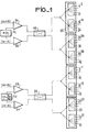
- the supply device comprises two inverters 49 and 50.
- the two inputs of the inverter 49 are supplied by means of two amplifier-modulators 51 and 52, respectively by the upper (w + Q) and lower ( ⁇ - ⁇ ) lateral bands, each of them being amplitude-modulated by a periodic HF voltage F (t), (G1) of period 2T o / N o , the shape can be for example in sinusoid arches.
- the inverter 50 is supplied by means of two amplifier-modulators 53 and 54, similarly by the same voltage but offset in time from (T o : rotation period of the two ideal antennas of the VOR Doppler system).
- the two inverters 49 and 50 are connected to four switches 55 with one input and N o / 4 outputs, allowing the supply of the antennas referenced from 1 to 48.
- the upper sideband ( ⁇ + ⁇ ) feeds two adjacent antennas (1 and 2 for example) while the lower sideband ( ⁇ - ⁇ ) feeds the two antennas diametrically opposite the first two
- a second drawback of the circular antenna array simulating the ideal rotation comes precisely from the high number of antennas and their proximity, causing parasitic coupling between them. Indeed, experience shows that the radiation of one antenna influences that of others, so that the amplitude and phase diagram of each antenna deviates significantly from omnidirectionality (of the order of 10 dB in amplitude and 50 ° in phase). In addition, it can be seen that the VOR Doppler system with two simultaneous lateral bands (DSB) exhibits significant parasitic phase and amplitude modulations of the signals transmitted by the central antenna due to the switching of the antennas of the circular network.
- DSB simultaneous lateral bands
- the power supply device of a radionavigation system of the VOR Doppler type, system radiating on the one hand omnidirectionally a VHF carrier wave modulated in amplitude and on the other by the two lateral bands of a amplitude modulation of this VHF wave, these two lateral bands being amplitude modulated by a periodic voltage F (t) and a device for switching the N o antennas of the circular array radiating the lateral bands, is such that it comprises means coupling and means for adding the amplitude modulated side bands, thus making it possible to produce a signal for supplying the antennas with a determined spectrum and compensating for the couplings existing between these antennas.
- the feed device comprises means for coupling and adding the amplitude modulated side bands placed upstream of the antenna switching device.
- these coupling and addition means are placed between the switching device and the N o antennas of the circular array transmitting the lateral bands of the VHF wave.
- FIG. 3 represents the diagram of an embodiment of a supply device for a VOR system, according to the invention.
- the two upper ( ⁇ + ⁇ ) and lower ( ⁇ - ⁇ ) lateral bands are delivered respectively by two generators 56 and 57, then modulated, by means of amplifier-modulators 58 to 61, by a periodic HF voltage, similar to the tension F (t) described in figure 1.
- F (t) is of the form cos X, with O ⁇ X ⁇ / 2
- F (t + T o / N o ) is of the form sin X, with O ⁇ X ⁇ / 2.
- the signals S 1 to S 4 delivered by the amplifier-modulators 58 to 61, each pass through a diode switch 61 i -i varying from 1 to 4-selecting an arch on two of the signals S 1 to S 4 Such sout switches known to the state of the art.
- the signals S 5 to S 12 from these switches are added in eight adder circuits 63 i -i varying from 1 to 8- to part of the signals S 1 to S 4 taken by four couplers 14 to 17.
- a periodic signal for feeding the antennas is obtained, corresponding to the upper lateral band ( ⁇ + ⁇ ), of period 4T o / N o , but offset in time by T o / N o at each output of circuits 63 1 to 63 4 .
- a supply signal corresponding to the lower lateral band ( ⁇ - ⁇ ) is obtained, similar to the previous one.
- Four inverter circuits 64, -i varying from 1 to 4- each receive as input the two supply signals, one corresponding to the upper side band and the other to the lower side band, coming from circuits 63 1 and 63 respectively.
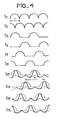
- FIG. 4 In FIG. 4 are shown the envelopes of the signals S 1 and S 2 , which are the same as those of the signals S 3 and S 4 ; those of signals S 5 to S 8 identical to those of signals S 9 to S 12 . Also shown are the envelopes of the signals S 13 to S 16 from the adder circuits 63, to 63 4 , envelopes similar to those of the signals S 17 to S 20 , which themselves represent the lower side band. It can be seen that the period T 'of the signals S 13 to S 16 is twice that of the signals F (t) and F (t + T o / N o ). Each antenna of the circular array transmitting the two lateral bands ⁇ ⁇ ⁇ of the VHF carrier wave is thus supplied for a time twice as long as in the previous embodiments.
- FIG. 5 shows the feeding device tripling the feeding time of the antennas Like the device in Figure 3, it has two generators 56 and 57 of the side bands ( ⁇ + ⁇ ) and ( ⁇ - ⁇ ) and four amplifier-modulators 58 to 61 modulating the lateral bands by an HF voltage.
- the signals S 1 to S 4 coming from these amplifier-modulators each pass through a diode switch 66, -i varying from 1 to 4- selecting one arch on three of these signals.
- the signals S 21 to S 32 from these switches are added in twelve adder circuits 67 i -ivariant from 1 to 12- to part of the signals S, to S 4 taken by eight couplers 68 i -i varying from 1 to 8-.
- Ai nsi for example, the signals S 21 , S 22 and S 23 coming from the switch 66, are each added on the one hand to a part of the signal S, taken by the coupler 68, and on the other hand to a part of the signal S 2 taken by the coupler 68 3 .
- the signals S 24 , S 25 and S 26 from the switch 66 2 are added on the one hand to a part of the signal S, taken by the coupler 68 2 and on the other hand to a part of the signal S 2 taken by the coupler 68 4 .
- the signals S 33 to S 38 supplying the antennas, at the output of circuits 67 1 to 67 6 , corresponding to the upper lateral band ( ⁇ + ⁇ ), are periodic with a period 6T o / N o , but shifted in time from T o / N o at each output of circuits 67, to 67 6 .
- the signals S 31 to S 41 corresponding to the side band ( ⁇ - ⁇ ).
- Six inverter circuits 64 i -i varying from 1 to 6- respectively receive the signals S 33 and S 39 , S 34 and S 40 , S 35 and S 4 ,, S 36 and S 42 , S 37 and S 43 and S 31 and S 44 and supply six switches 69, to 69 6 themselves connected to the antennas of the circular array.
- the high number and proximity of the antennas cause parasitic coupling effects.
- the levels of the signals S 1 and S 2 sampled by the couplers, in Figures 3 and 5 must take account of these couplings, the most harmful influence of which is not due to the neighboring antennas but at more distant antennas, due to the greater difference between the phase centers of the antennas.
- the elements 74 are simple transformers of ratio 2 and the coupling elements 73 are series resistors.
- a device for supplying a VOR Doppler system has thus been described, the performance of which is significantly improved compared to that of the prior art. Thanks to this new device, the parasitic modulations of phase and amplitude of the carrier wave emitted by the central antenna, as of the two lateral bands emitted by the circular array of antennas are considerably reduced.
Landscapes
- Engineering & Computer Science (AREA)
- Computer Networks & Wireless Communication (AREA)
- Physics & Mathematics (AREA)
- General Physics & Mathematics (AREA)
- Radar, Positioning & Navigation (AREA)
- Remote Sensing (AREA)
- Variable-Direction Aerials And Aerial Arrays (AREA)
Claims (10)
Applications Claiming Priority (2)
| Application Number | Priority Date | Filing Date | Title |
|---|---|---|---|
| FR8004950A FR2477722A1 (fr) | 1980-03-05 | 1980-03-05 | Dispositif d'alimentation d'un systeme de radionavigation du type vor doppler et systeme vor doppler le comprenant |
| FR8004950 | 1980-03-05 |
Publications (2)
| Publication Number | Publication Date |
|---|---|
| EP0035441A1 EP0035441A1 (de) | 1981-09-09 |
| EP0035441B1 true EP0035441B1 (de) | 1985-02-13 |
Family
ID=9239345
Family Applications (1)
| Application Number | Title | Priority Date | Filing Date |
|---|---|---|---|
| EP81400288A Expired EP0035441B1 (de) | 1980-03-05 | 1981-02-24 | Speiseleitungsgerät für Doppler-VOR-Radionavigationssystem und seine Verwendung |
Country Status (7)
| Country | Link |
|---|---|
| US (1) | US4382259A (de) |
| EP (1) | EP0035441B1 (de) |
| JP (1) | JPS56138259A (de) |
| AU (1) | AU538351B2 (de) |
| CA (1) | CA1164985A (de) |
| DE (1) | DE3168846D1 (de) |
| FR (1) | FR2477722A1 (de) |
Families Citing this family (9)
| Publication number | Priority date | Publication date | Assignee | Title |
|---|---|---|---|---|
| US4641143A (en) * | 1983-09-28 | 1987-02-03 | Sanders Associates, Inc. | Two-dimensional acquisition system using circular array |
| US6366627B1 (en) | 1983-09-28 | 2002-04-02 | Bae Systems Information And Electronic Systems Integration, Inc. | Compressive receiver with frequency expansion |
| US4604626A (en) * | 1983-11-21 | 1986-08-05 | Sanders Associates, Inc. | Acquisition system employing circular array |
| JPH0492378U (de) * | 1990-12-27 | 1992-08-11 | ||
| IT1273392B (it) * | 1994-03-31 | 1997-07-08 | Alcatel Air Navigation Systems | Metodo e dispositivo di alimentazione, in particolare per un sistema vor doppler, modulatore adatto per gli stessi e sistema vor doppler |
| US5574467A (en) * | 1995-03-09 | 1996-11-12 | Interval Research Corporation | Doppler positioning using non-planar movement of transmitting source and receiving source |
| EP1868007B1 (de) * | 2006-06-13 | 2012-10-17 | Kabushiki Kaisha Toshiba | Phasenkorrekturgerät, inbesondere für Doppler-VOR Antennenarray |
| KR100818021B1 (ko) | 2006-11-03 | 2008-03-31 | 한국공항공사 | 도플러전방향표지시설 시뮬레이션 방법 |
| US7489274B2 (en) * | 2006-11-27 | 2009-02-10 | Honeywell International Inc. | System and method for generating a very high frequency omnidirectional range signal |
Citations (1)
| Publication number | Priority date | Publication date | Assignee | Title |
|---|---|---|---|---|
| US3896444A (en) * | 1974-01-09 | 1975-07-22 | Amalgamated Wireless Australas | Blending function and blending function generator |
Family Cites Families (1)
| Publication number | Priority date | Publication date | Assignee | Title |
|---|---|---|---|---|
| NL7603687A (nl) * | 1976-04-08 | 1977-10-11 | Philips Nv | Vermogensverdeel- en modulatie-inrichting. |
-
1980
- 1980-03-05 FR FR8004950A patent/FR2477722A1/fr active Granted
-
1981
- 1981-02-24 EP EP81400288A patent/EP0035441B1/de not_active Expired
- 1981-02-24 DE DE8181400288T patent/DE3168846D1/de not_active Expired
- 1981-03-03 CA CA000372206A patent/CA1164985A/en not_active Expired
- 1981-03-04 JP JP3108481A patent/JPS56138259A/ja active Granted
- 1981-03-04 US US06/240,283 patent/US4382259A/en not_active Expired - Lifetime
- 1981-03-05 AU AU68095/81A patent/AU538351B2/en not_active Expired
Patent Citations (1)
| Publication number | Priority date | Publication date | Assignee | Title |
|---|---|---|---|---|
| US3896444A (en) * | 1974-01-09 | 1975-07-22 | Amalgamated Wireless Australas | Blending function and blending function generator |
Also Published As
| Publication number | Publication date |
|---|---|
| AU6809581A (en) | 1981-09-10 |
| DE3168846D1 (en) | 1985-03-28 |
| FR2477722B1 (de) | 1983-07-22 |
| FR2477722A1 (fr) | 1981-09-11 |
| US4382259A (en) | 1983-05-03 |
| EP0035441A1 (de) | 1981-09-09 |
| JPS56138259A (en) | 1981-10-28 |
| AU538351B2 (en) | 1984-08-09 |
| CA1164985A (en) | 1984-04-03 |
| JPS6339876B2 (de) | 1988-08-08 |
Similar Documents
| Publication | Publication Date | Title |
|---|---|---|
| EP0035441B1 (de) | Speiseleitungsgerät für Doppler-VOR-Radionavigationssystem und seine Verwendung | |
| EP0716751B1 (de) | Sonarsystem für strömungsgeschwindigkeitmesser und dopplerlog | |
| US4054841A (en) | Differential demodulators using surface elastic wave devices | |
| EP0143497B1 (de) | Mit stetigen frequenzmodulierten Wellen arbeitendes Monopulsradargerät mit Achsenstabilisierung | |
| EP0002642B1 (de) | Antennesystem hohen Trennvermögens | |
| FR2543379A1 (fr) | Dispositif de demodulation directe en hyperfrequence et chaine de reception hyperfrequence comportant un tel dispositif | |
| FR2519770A1 (fr) | Systeme d'antenne a pouvoir separateur eleve | |
| FR2661561A1 (fr) | Systeme d'antenne de radiogoniometrie a couverture omnidirectionnelle. | |
| FR2465233A1 (fr) | Appareil de determination de gisement a radar ultrasonore | |
| EP0072316B1 (de) | Antenne mit elektronischer Schwenkung und mehreren Eingängen und Radar mit einer solchen Antenne | |
| EP0034974A1 (de) | Überwachungsgerät für Doppler-VOR-Radionavigationssystem und damit ausgestattetes Doppler-VOR-System | |
| EP0028182A1 (de) | Frequenzmoduliertes Bord-Radargerät und seine Anwendung bei einem sich selbst lenkenden Flugkörper | |
| EP0083534B1 (de) | MLS(Mikrowellenlandesystem) mit Entstörungsmittel | |
| EP0478424A1 (de) | Verfahren und Vorrichtung zur Messung der Integrität einer Sendung | |
| EP0107596B1 (de) | Notfunkbake zur Verwendung bei Schiffbruch | |
| FR2601143A1 (fr) | Procede et systeme de localisation et de correction d'orientation d'un objet mobile autonome et d'un objet mobile non autonome | |
| EP0225218A1 (de) | Verfahren zur Frequenzsynthese und dieses Verfahren verwendendes Synthesierergerät | |
| EP0055636B1 (de) | Abweichungsempfänger für Sekundärradar | |
| FR2549321A1 (fr) | Procede d'augmentation de portee, et notamment de protection contre le brouillage, d'un systeme d'aide a l'atterrissage de type mls, et dispositifs de mise en oeuvre d'un tel procede | |
| FR2464484A1 (fr) | Radar doppler a onde continue et a codage pseudo-aleatoire pour la mesure d'angle et de distance | |
| EP0380397B1 (de) | Gegentakt-Modulator für ein elektromagnetisches Mikrowellensignal hoher Leistung | |
| FR2460050A1 (fr) | Systeme de transmission hyperfrequence de donnees numeriques | |
| EP0232901B1 (de) | Hohlleiterleistungsverteiler für eine linearpolarisierte Welle | |
| FR2602096A1 (fr) | Procede et dispositif de compensation de la dispersion en frequence d'une antenne a balayage electronique, et son application a un systeme d'aide a l'atterrissage de type mls | |
| EP0624804A1 (de) | Zielverfolgungssystem zur Schätzung des Ausrichtungsfehlers einer HF-Antenne |
Legal Events
| Date | Code | Title | Description |
|---|---|---|---|
| PUAI | Public reference made under article 153(3) epc to a published international application that has entered the european phase |
Free format text: ORIGINAL CODE: 0009012 |
|
| AK | Designated contracting states |
Designated state(s): CH DE GB IT LI NL |
|
| 17P | Request for examination filed |
Effective date: 19811217 |
|
| ITF | It: translation for a ep patent filed | ||
| GRAA | (expected) grant |
Free format text: ORIGINAL CODE: 0009210 |
|
| AK | Designated contracting states |
Designated state(s): CH DE GB IT LI NL |
|
| REF | Corresponds to: |
Ref document number: 3168846 Country of ref document: DE Date of ref document: 19850328 |
|
| PLBE | No opposition filed within time limit |
Free format text: ORIGINAL CODE: 0009261 |
|
| STAA | Information on the status of an ep patent application or granted ep patent |
Free format text: STATUS: NO OPPOSITION FILED WITHIN TIME LIMIT |
|
| 26N | No opposition filed | ||
| ITTA | It: last paid annual fee | ||
| PGFP | Annual fee paid to national office [announced via postgrant information from national office to epo] |
Ref country code: CH Payment date: 19950116 Year of fee payment: 15 |
|
| PGFP | Annual fee paid to national office [announced via postgrant information from national office to epo] |
Ref country code: NL Payment date: 19950228 Year of fee payment: 15 |
|
| PG25 | Lapsed in a contracting state [announced via postgrant information from national office to epo] |
Ref country code: LI Free format text: LAPSE BECAUSE OF NON-PAYMENT OF DUE FEES Effective date: 19960228 Ref country code: CH Free format text: LAPSE BECAUSE OF NON-PAYMENT OF DUE FEES Effective date: 19960228 |
|
| PG25 | Lapsed in a contracting state [announced via postgrant information from national office to epo] |
Ref country code: NL Effective date: 19960901 |
|
| REG | Reference to a national code |
Ref country code: CH Ref legal event code: PL |
|
| NLV4 | Nl: lapsed or anulled due to non-payment of the annual fee |
Effective date: 19960901 |
|
| PGFP | Annual fee paid to national office [announced via postgrant information from national office to epo] |
Ref country code: GB Payment date: 20000119 Year of fee payment: 20 |
|
| PGFP | Annual fee paid to national office [announced via postgrant information from national office to epo] |
Ref country code: DE Payment date: 20000211 Year of fee payment: 20 |
|
| PG25 | Lapsed in a contracting state [announced via postgrant information from national office to epo] |
Ref country code: GB Free format text: LAPSE BECAUSE OF EXPIRATION OF PROTECTION Effective date: 20010223 |
|
| REG | Reference to a national code |
Ref country code: GB Ref legal event code: PE20 Effective date: 20010223 |