EP0034865B1 - Arrangement for the transmission of audio signals - Google Patents
Arrangement for the transmission of audio signals Download PDFInfo
- Publication number
- EP0034865B1 EP0034865B1 EP81200187A EP81200187A EP0034865B1 EP 0034865 B1 EP0034865 B1 EP 0034865B1 EP 81200187 A EP81200187 A EP 81200187A EP 81200187 A EP81200187 A EP 81200187A EP 0034865 B1 EP0034865 B1 EP 0034865B1
- Authority
- EP
- European Patent Office
- Prior art keywords
- arrangement
- output
- delay line
- amplitude control
- input
- Prior art date
- Legal status (The legal status is an assumption and is not a legal conclusion. Google has not performed a legal analysis and makes no representation as to the accuracy of the status listed.)
- Expired
Links
Images

Classifications
-
- G—PHYSICS
- G10—MUSICAL INSTRUMENTS; ACOUSTICS
- G10K—SOUND-PRODUCING DEVICES; METHODS OR DEVICES FOR PROTECTING AGAINST, OR FOR DAMPING, NOISE OR OTHER ACOUSTIC WAVES IN GENERAL; ACOUSTICS NOT OTHERWISE PROVIDED FOR
- G10K15/00—Acoustics not otherwise provided for
- G10K15/08—Arrangements for producing a reverberation or echo sound
- G10K15/12—Arrangements for producing a reverberation or echo sound using electronic time-delay networks
Definitions
- the invention relates to an arrangement for the transmission of audio signals the arrangement having an input and an output and comprising a delay line, provided with an input coupled to the arrangement input and 2k+1 tappings (k being an integer and 2 ⁇ k ⁇ 4), which tappings are situated at equal time intervals (t,) and are each connected to a common adding circuit via a first amplitude control device, the amplitudes of the signals on the outputs of those first amplitude control devices which are connected to tappings which are situated symmetrically relative to the central tapping having equal values, the phase shifts in the first amplitude control devices being the same, except that the phase shift in one of every two of those first amplitude control devices which are situated at equal odd multiples of the time interval (t 1 ) from the central tapping differs by 180° from that in the other and the amplitudes of said signals being selected so that the transmission from the input of the delay line to an output of the common adding circuit is at least substantially frequency-independent.
- the invention also relates to a reverberation unit provided with such
- the ratios between the amplitudes of the signals on the outputs of the amplitude control device are chosen in the known arrangement to accord with the coefficients of the Bessel function of the first kind and with an argument corresponding to half the largest odd number of tappings in the arrangement minus three. Because of this, the arrangement can supply an output signal whose amplitude, when signals of constant amplitude but arbitrary frequency are applied to the arrangement, is substantially frequency-independent.
- the known arrangement has the drawback that, especially if the delay line is a digital delay line (shift register) or a charge transfer device, for example a bucket brigade or charge-coupled device, the Bessel coefficients to be used for the various amplitude control devices yield inconvenient values, which are often difficult to realize by digital or analogue means, so that the arrangement can be realized only with very intricate digital or analogue circuits.
- the delay line is a digital delay line (shift register) or a charge transfer device, for example a bucket brigade or charge-coupled device
- the Bessel coefficients to be used for the various amplitude control devices yield inconvenient values, which are often difficult to realize by digital or analogue means, so that the arrangement can be realized only with very intricate digital or analogue circuits.
- the arrangement comprises p such delay lines (p> 1 ) and that when an index x (x being an integer ⁇ k+ 1 ) is assigned to each of the tappings of a delay line, the index 1 being assigned to one of the extreme tappings, consecutive indices to consecutive adjacent tappings, proceeding from said extreme tapping to the central tapping, and the highest index to the central tapping, the ratios between the output signals of the amplitude control devices A x associated with said tappings, including their signs, satisfy the equation:
- n is not necessarily an integer.
- a small value will be selected for n, because in that case all tappings contribute substantially equally to the output signal of the common adding circuit.
- the delay line itself exhibits a frequency-independent transmission from the input to the various tappings.
- An embodiment of the arrangement in accordance with the invention may comprise at least two delay lines, the input of each consecutive delay line being connected to the output of the common adding circuit of the delay line which precedes it, the output of the common adding circuit of the last delay line being coupled to the output of the arrangement.
- a second embodiment of the arrangement in accordance with the invention is characterized in that the arrangement comprises 21+1 series-connected identical delay lines (I being an integer and 2 ⁇ 1 ⁇ 4), the input of each consecutive delay line being connected to an output of the delay line preceding it, and the outputs of the common adding circuits of the (21+1) delay lines being individually provided with a second amplitude control device, the output of each second amplitude control device being connected to a further common adding circuit whose output is coupled to the output of the arrangement, the amplitudes of the output signals of those second amplitude control devices of delay lines which are disposed symmetrically relative to the central delay line having equal values and the phase shifts in the second amplitude control devices being equal, except that the phase shift in one of every two of those second amplitude control devices situated at equal odd multiples of the time interval (t 2 ), which corresponds to the time interval between the central tappings of two consecutive delay lines, from the central tapping of the central delay line differs by 180° from that in the other, and that when an index x (x
- the 21+1 delay lines are combined to one delay line with 21+1 groups of 2k+1 tappings. This makes it possible to combine the delay lines in such a way that the time interval t 2 becomes smaller than the sum of the time intervals between the central tapping and the extreme tapping of two adjacent delay lines, so that a much shorter total delay time in the arrangement and consequently less components for the delay lines are needed.
- n is equal to 1 for at least one delay line.
- the ratios between the output signals of the amplitude control devices in the arrangements provided with a delay line having 5, 7 or 9 tappings are then and respectively.
- Such an arrangement has the advantage that the amplitudes of said signals do not differ excessively in magnitude and that owing to the simple ratio between them the amplitude control devices can be simplified and in the case of digital signals the multiplications and/or divisions can be performed by shifting the bits one position.
- Another embodiment of an arrangement in accordance with the invention is characterized in that at least one delay line comprises 7 tappings and that the output signals of the first amplitude control devices, viewed from one end of the delay line to the other end, are in the ratio of
- a further embodiment of the arrangement is characterized in that at least one delay line comprises 7 tappings and the output signals of the first amplitude control devices, viewed from one end of the delay line to the other end, are in the ratio of
- Yet another embodiment is characterized in that at least one delay line has 7 tappings and that the output signals of the first amplitude control devices, viewed from one end of the delay line to the other end, are in the ratio of
- the advantage of these ratios is that, in the case of digitized signal transmission, the multiplications and/or divisions can be performed by shifting the bits one or more positions, corresponding to the relevant powers of 2 in the ratios.
- Another embodiment of said arrangement is characterized in that the arrangement comprises 7 delay lines and that the output signals of the second amplitude control devices, viewed from one end to the other end, are in the ratio of
- a further embodiment of said device is characterized in that the arrangement comprises 7 delay lines and that the output signals of the second amplitude control devices, viewed from one end to the other end, are in the ratio of
- Yet another embodiment of said arrangement is characterized in that the arrangement comprises 7 delay lines and that the output signals of the second amplitude control devices, viewed from one end to the other end, are in the ratio of
- the advantage of these ratios is that, in particular in the case of digitized signal transmission, the multiplications and/or divisions can be performed by shifting the bits one or more positions, corresponding to the relevant powers of 2 in the ratios.
- a reverberation unit is characterized in that there is provided an arrangement in accordance with the invention, a signal being applied to a first input of a combination unit, whilst the output of the combination unit is connected, optionally via an additional delay line, to the input of the arrangement, the output of the arrangement being connected, optionally via an amplifier or attenuator stage, to a second input of the combination unit.
- the output signal of the arrangement By feeding the output signal of the arrangement back to the input of the arrangement, the output of the arrangement being constituted by the output of the adding circuit associated with the (last) delay line or the output of the further common adding circuit of the arrangement, a desired reverberation is obtained.
- the loop gain should be smaller than unity. This results in reflections which decay in time, which gives the impression of reverberation.
- a special embodiment of a reverberation unit in accordance with the invention provided with an arrangement with at least two delay lines, the output of each consecutive delay line being coupled to the output of the common adding circuit associated with the delay line preceding it, is characterized in that the arrangement comprises 2 delay lines, each provided with 7 tappings, the time interval between the tappings of the one delay line being unequel to that of the other delay line, and the output of the common adding circuit of the second delay line constituting the output of the arrangement.
- a further embodiment of the reverberation unit in accordance with the invention is characterized in that the output of the combination unit is connected, optionally via a further amplifier or attenuator stage, to a first input of a further combination unit, and the output of the arrangement is connected, optionally via another amplifier or attenuator stage, to a second input of the further combination unit, on whose output the output signal is available.
- the loop gain viewed from the input of the reverberation unit via the arrangement and the feedback circuit to the second input of the combination unit, is equal to but of a sign opposite to the ratio between the gain in the path from the input of the reverberation unit to the first input of the further combination unit and the gain in the path from the input of the reverberation unit via the output of the arrangement to the second input of the further combination unit.
- this moreover yields the advantage that the feedback circuit to the second input of the combination unit can be realized without an amplifier or attenuator.
- Yet another embodiment of a reverberation unit in accordance with the invention is characterized in that there is provided an arrangement in accordance with the invention provided with one delay line with two identical groups of 2k+ 1 tappings together with associated amplitude control devices and adding circuits, the output of the common adding circuit of the first group being connected, optionally via an amplifier or attenuator stage, to the second input of the combination unit, and the output of the common adding circuit of the second group being connected, optionally via a further amplifier or attenuator stage, to a first input of a further combination unit, the output of the delay line being connected, optionally via another amplifier or attenuator stage, to a second input of the further combination unit, on whose output the desired signal is available, that the ratios between the output signals of successive amplitude control devices of one group, viewed from the input of the delay line , are equal to the ratios between the output signals of successive amplitude control devices of the other group, viewed from the output
- the application of the output signal of the common adding circuit of the second group to the first input of the further combination unit which also in this case is intended for flattening the frequency response curve of the reverberation unit, is obtained by again applying the principle of the invention to the second group of (2k+1 ) tappings along the delay line. Also in this case a flat frequency response curve is obtained if the loop gain, viewed from the input of the reverberation unit, via the arrangement and the feedback circuit, to the second input of the combination unit, is equal to but of a sign opposite to the ratio of the gain between the input of the reverberation unit and the first input of the further combination unit to the gain between the input of the reverberation unit and the second input of the further combination unit via the delay line.
- both the feedback circuit to the second input of the first combination unit and the path to the first input of the further combination unit may be realized without amplifiers or attenuators.
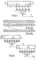
- the arrangement of Figure 1 is provided with a delay line 1, an input 2 to which an audio frequency signal is applied and an output 15.
- the delay line 1 comprises an input coupled to the arrangement input 2, an output 3 and five tappings 4 to 8 for taking a signal off the delay line.
- the tappings 4 to 8 are situated at equal delay intervals t, along the delay line.
- the delays between the input 2 of the delay line and the first tapping 4 (to) and between the last tapping 8 and the output 3 of the delay line (t 3 ) may be arbitrary.
- the tappings 4 to 8 are each connected to the output 15 of the arrangement via a respective amplitude control device 9 to 13 and an adding circuit 16.
- the elements 9 to 13 amplify or attenuate the signals from the corresponding tappings 4 to 8 by the respective factors a 1 to a 5 and may be constituted by analogue or digital amplifiers or attenuators.
- n is an integer.
- n is not selected too high, and is selected for example equal to
- analogue signal is digitally transmitted in the arrangement, this means that the (digitally 5 represented) amplitudes of the signals on the tappings 5, 6 and 7 need neither be amplified nor attenuated and that the amplitudes on the two outer tappings should be divided by 2.
- This division is very simple by digital means. Assume, for example, that the analogue signal amplitudes are represented by 16-bit binary numbers.
- the delay line 1 may then comprise 16 parallel shift-registers. Each tapping, for example 4, taps one bit of the binary number out of each of the 16 shift registers and sets this number in a 16-bit shift-register associated with the amplitude control device.
- the arrangement shown in Figure 1 may alternatively be provided with 7 tappings.
- the ratios between the amplitudes of the signals on the outputs of the amplitude control devices are then Preferably, a small value is selected for n.
- the arrangement as shown in Figure 1 may alternatively be provided with 9 tappings.
- the ratios between the amplitudes of the signals on the outputs of the amplitude control devices will then be Again a small value is preferably selected for n. If n is selected to be 1, the ratios will be If these figures are divided by the highest value, this results in i.e. the tappings adjacent the central tapping may be dispensed with. Division by 2 is required for the two extreme tappings, i.e. a binary shift through one position in the direction of the least significant bit.
- Figure 3 shows an arrangement in accordance with the invention provided with two or more delay lines 21,22,... each similar to that shown in Figure 1.
- Each delay line may be provided with 5, 7 or 9 tappings.
- Figure 3 shows a delay line 21 and 7 tappings and amplitude control devices giving factors a 1 toa7, and a delay line 22 also having 7 tappings and amplitude control devices giving factors b 1 to b 7 .
- the ratios between the amplitudes of the output signals of the amplitude control devices may differ for the two delay lines provided of course that they conform with expression (1).
- the delays t 1 and t 5 respectively between the tappings of the two delay lines and the delays to and t 4 respectively from the input to the first tappings of these delay lines may differ.
- the output of the common adding circuit 23 of the first delay line 21 is connected to the input of the second delay line 22.
- the output of the common adding circuit 24 of the second delay line 22 is either connected to the input of the next delay line or, if only two delay lines are present, is connected to the output 15 of the arrangement.
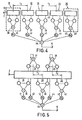
- Figure 4 shows another arrangement comprising a series connection of five identical delay lines 31 to 35 provided with 5, 7 or 9 tappings.
- the ratios between the amplitudes on the outputs of the amplitude control devices associated with the tappings are the same for all delay lines.
- the output of the first delay line 31 is connected to the input of the second delay line 32.
- the input of each succeeding delay line is connected to the output of the delay line preceding it.
- the time interval between the central tappings of every two consecutive delay lines is t 2 .
- the outputs of the common adding circuits 36 to 40 associated with respective ones of the delay lines 31 to 35 are each connected to the output 15 of the arrangement via second amplitude control devices, represented by the respective elements 41 to 45, and a further common adding circuit 46.
- the elements 41 to 45 amplify or attenuate the signals on the outputs of the common adding circuits 36 to 40 by respective factors b 1 to b 5 , namely in such a way that the ratios between the amplitudes of the output signals of the second amplitude control devices 41 to 45, viewed from one end of the arrangement to the other end, are
- This arrangement has a substantially frequency-independent transmission characteristic.
- the arrangement may alternatively be equipped with 7 or 9 series connected delay lines each with 5, 7 or 9 tappings.
- the corresponding amplitudes on the outputs of the second amplitude control devices then are in the ratios for 7 delay lines and for 9 delay lines.
- the delay lines 31 to 35 of Figure 4 are effectively interlaced in such a way that the delay t 2 occurring between the central tappings on two delay lines which are disposed "adjacent" each other is smaller than the sum of the delay occurring between the central tapping and the output of a given delay line and the delay occurring between the input and the central tapping of the next delay line.
- the tappings associated with the delay lines 32 and 34 are shown at the top of the delay line.
- a reverberation unit In order to obtain a reverberation unit with the aid of an arrangement in accordance with the invention, which arrangement in principle only supplies an output signal together with delayed versions thereof, i.e. a unit supplying a signal which recurs with an amplitude which decreases in time (corresponding to genuine echoes), the output signal of the arrangement should be fed back to its input.
- a reverberation unit is shown in Figure 6.
- the framed part 50 represents the arrangement, which has an input 2 and an output 15.
- the framed part 50 may thus contain any of the embodiments of Figures 1, 3, 4 and 5.
- the arrangement 50 is preceded by a combination unit 52. Between the combination unit and the arrangement 50 an additional delay line 53 giving a fixed delay may be included.
- the input 51 of the reverberation unit is connected to a first input of the combination unit 52.
- the output 15 of the arrangement is connected to the output 55 of the reverberation unit and, optionally via a feedback amplifier or attenuator 54, to a second input of the combination unit 52.
- the gain around the loop containing the combination unit 52, the delay line 53, the arrangement 50 and the feedback amplifier 54 should be smaller than unity, i.e. Aa: ⁇ 1, A being the gain of the arrangement 50 from input 2 to output 15 and assuming that the gains of delay line 53 and combination unit 52 are unity.
- the arrangement 50 comprises two delay lines having 7 tappings each, as shown in Figure 3.
- a reverberation unit it is possible to obtain a very faithful simulation of three-dimensional reverberation, i.e. reverberation in a three-dimensional space such as a concert hall.
- the two time intervals quoted in Fig. 3 for the two delay lines it is possible to obtain a desired increase in the "density" of the successive echoes, with a rapid square-law increase of the number of echoes per unit of time.
- a reverberation unit By merely feeding back the output signal to the input of the arrangement 50 a reverberation unit is obtained which is no longer frequency-independent, i.e. no longer exhibits a flat frequency response from input 51 to output 55.
- the arrangement 50 and, if present, the preceding delay line 53 is bridged by a transmission path 56, in which an amplifier 57 may be included, which transmission path is connected to a first input of a further combination unit 58 in the form of an adder, and the output 15 of the arrangement 50, optionally via an amplifier or attenuator 59, is connected to a second input of the further combination unit 58, a reverberation unit can be obtained which has a frequency-independent transmission characteristic from input 51 to output 55, which output is connected to the output of the further combination unit 58.
- FIG 8 shows a particular embodiment of the reverberation unit of Figure 7.
- the 5, 7 or 9 tappings of the delay line, provided with respective amplitude control devices and an adder, are denoted by the reference numeral 60.
- the output 15 of the arrangement 60 is fed back to the second input of the combination unit 52 via a feedback amplifier 54.
- the output 3 of the delay line is now connected to the second input of the further combination unit 58 via the amplifier 59.
- the reference numeral 61 denotes an equal number of tappings and associated amplitude control devices (together with an associated adder) to those shown for 60.
- the delays between the tappings of 60 and 61 are equal (t,).
- the ratios between the amplitudes of the output signals of the amplitude control devices associated with the tappings of 60, viewed in a direction along the delay line, are the same as for the tappings of 61, but then viewed in a direction opposite to the said direction.
- the delay to between the input of the delay line and the first tapping of 60 is equal to the delay between the last tapping of 61 and the end of the delay line 1.
- the delay t 4 between the input of the delay line 1 and the first tapping of 61 is equal to the delay between the last tapping of 60 and the end of the delay line 1.
- Delay t 4 may be greater or smaller than or equal to to.
- 60 and 61 are arranged mirror-symmetrically relative to the centre of the delay line 1.
- the output 63 of the arrangement 61 is connected to the first input of the further combination unit 58 by means of the transmission path 56, which may include the amplifier 57.
- the transmission path 56 which may include the amplifier 57.
Landscapes
- Physics & Mathematics (AREA)
- Engineering & Computer Science (AREA)
- Acoustics & Sound (AREA)
- Multimedia (AREA)
- Reverberation, Karaoke And Other Acoustics (AREA)
- Circuit For Audible Band Transducer (AREA)
- Electrophonic Musical Instruments (AREA)
- Stereophonic System (AREA)
Description
- The invention relates to an arrangement for the transmission of audio signals the arrangement having an input and an output and comprising a delay line, provided with an input coupled to the arrangement input and 2k+1 tappings (k being an integer and 2≤k≤4), which tappings are situated at equal time intervals (t,) and are each connected to a common adding circuit via a first amplitude control device, the amplitudes of the signals on the outputs of those first amplitude control devices which are connected to tappings which are situated symmetrically relative to the central tapping having equal values, the phase shifts in the first amplitude control devices being the same, except that the phase shift in one of every two of those first amplitude control devices which are situated at equal odd multiples of the time interval (t1) from the central tapping differs by 180° from that in the other and the amplitudes of said signals being selected so that the transmission from the input of the delay line to an output of the common adding circuit is at least substantially frequency-independent. The invention also relates to a reverberation unit provided with such an arrangement in accordance with the invention. An arrangement of the type mentioned in the preamble is known from Netherlands Patent Specification number 112,868.
- The ratios between the amplitudes of the signals on the outputs of the amplitude control device are chosen in the known arrangement to accord with the coefficients of the Bessel function of the first kind and with an argument corresponding to half the largest odd number of tappings in the arrangement minus three. Because of this, the arrangement can supply an output signal whose amplitude, when signals of constant amplitude but arbitrary frequency are applied to the arrangement, is substantially frequency-independent.
- The known arrangement has the drawback that, especially if the delay line is a digital delay line (shift register) or a charge transfer device, for example a bucket brigade or charge-coupled device, the Bessel coefficients to be used for the various amplitude control devices yield inconvenient values, which are often difficult to realize by digital or analogue means, so that the arrangement can be realized only with very intricate digital or analogue circuits.
- It is an object of the invention to provide an arrangement which, whilst maintaining the advantages of the known arrangement, is much simpler to realize. This object is met in that the arrangement comprises p such delay lines (p> 1 ) and that when an index x (x being an integer <k+ 1 ) is assigned to each of the tappings of a delay line, the
index 1 being assigned to one of the extreme tappings, consecutive indices to consecutive adjacent tappings, proceeding from said extreme tapping to the central tapping, and the highest index to the central tapping, the ratios between the output signals of the amplitude control devices Ax associated with said tappings, including their signs, satisfy the equation: -

- By limiting the number of tappings of one delay line to a maximum of 9 and selecting the ratios between the signal amplitudes in accordance with the specified equation, an arrangement which is very simple to realize can be obtained, which nevertheless exhibits a substantially frequency-independent transmission.
- It is to be noted that n is not necessarily an integer. Suitably, a small value will be selected for n, because in that case all tappings contribute substantially equally to the output signal of the common adding circuit. Moreover, it has been assumed in the foregoing that the delay line itself exhibits a frequency-independent transmission from the input to the various tappings.
- An embodiment of the arrangement in accordance with the invention may comprise at least two delay lines, the input of each consecutive delay line being connected to the output of the common adding circuit of the delay line which precedes it, the output of the common adding circuit of the last delay line being coupled to the output of the arrangement. By arranging at least two delay lines in the manner described, the time intervals between the tappings of the two delay lines can be selected differently, so that unequal time delays can be realized, whilst the arrangement yet exhibits a frequency-independent transmission characteristic.
- A second embodiment of the arrangement in accordance with the invention is characterized in that the arrangement comprises 21+1 series-connected identical delay lines (I being an integer and 2≤1≤4), the input of each consecutive delay line being connected to an output of the delay line preceding it, and the outputs of the common adding circuits of the (21+1) delay lines being individually provided with a second amplitude control device, the output of each second amplitude control device being connected to a further common adding circuit whose output is coupled to the output of the arrangement, the amplitudes of the output signals of those second amplitude control devices of delay lines which are disposed symmetrically relative to the central delay line having equal values and the phase shifts in the second amplitude control devices being equal, except that the phase shift in one of every two of those second amplitude control devices situated at equal odd multiples of the time interval (t2), which corresponds to the time interval between the central tappings of two consecutive delay lines, from the central tapping of the central delay line differs by 180° from that in the other, and that when an index x (x being an integer <I+1 ) is assigned to each of the delay lines, the
index 1 being assigned to one of the extreme delay lines, consecutive indices to consecutive adjacent delay lines, proceeding from said extreme delay line to the central delay line, and the highest index to the central delay line, the ratios between the output signals of the second amplitude control devices Bx associated with said delay lines including their signs, satisfy the equation
- In a further embodiment of the said arrangement in accordance with the invention the 21+1 delay lines are combined to one delay line with 21+1 groups of 2k+1 tappings. This makes it possible to combine the delay lines in such a way that the time interval t2 becomes smaller than the sum of the time intervals between the central tapping and the extreme tapping of two adjacent delay lines, so that a much shorter total delay time in the arrangement and consequently less components for the delay lines are needed.
- In another arrangement in accordance with the invention n is equal to 1 for at least one delay line. The ratios between the output signals of the amplitude control devices in the arrangements provided with a delay line having 5, 7 or 9 tappings are then


- Another embodiment of an arrangement in accordance with the invention is characterized in that at least one delay line comprises 7 tappings and that the output signals of the first amplitude control devices, viewed from one end of the delay line to the other end, are in the ratio of

- A further embodiment of the arrangement is characterized in that at least one delay line comprises 7 tappings and the output signals of the first amplitude control devices, viewed from one end of the delay line to the other end, are in the ratio of

- Yet another embodiment is characterized in that at least one delay line has 7 tappings and that the output signals of the first amplitude control devices, viewed from one end of the delay line to the other end, are in the ratio of

- The advantage of these ratios is that, in the case of digitized signal transmission, the multiplications and/or divisions can be performed by shifting the bits one or more positions, corresponding to the relevant powers of 2 in the ratios.
- In one arrangement in accordance with the invention with 21+1 series-connected delay lines m is 1. The ratios between the output signals of the second amplitude control devices are then


- Another embodiment of said arrangement is characterized in that the arrangement comprises 7 delay lines and that the output signals of the second amplitude control devices, viewed from one end to the other end, are in the ratio of
-

- A further embodiment of said device is characterized in that the arrangement comprises 7 delay lines and that the output signals of the second amplitude control devices, viewed from one end to the other end, are in the ratio of

- Yet another embodiment of said arrangement is characterized in that the arrangement comprises 7 delay lines and that the output signals of the second amplitude control devices, viewed from one end to the other end, are in the ratio of

- It is of course clear, that a tapping and an associated first amplitude control device, on whose output an at least approximately zero amplitude should be available, may be dispensed with. As a consequence an arrangement is obtained which has two of its tappings now situated twice the time interval t1 apart.
- A reverberation unit, is characterized in that there is provided an arrangement in accordance with the invention, a signal being applied to a first input of a combination unit, whilst the output of the combination unit is connected, optionally via an additional delay line, to the input of the arrangement, the output of the arrangement being connected, optionally via an amplifier or attenuator stage, to a second input of the combination unit. By feeding the output signal of the arrangement back to the input of the arrangement, the output of the arrangement being constituted by the output of the adding circuit associated with the (last) delay line or the output of the further common adding circuit of the arrangement, a desired reverberation is obtained. In order to prevent instabilities, the loop gain should be smaller than unity. This results in reflections which decay in time, which gives the impression of reverberation.
- A special embodiment of a reverberation unit in accordance with the invention, provided with an arrangement with at least two delay lines, the output of each consecutive delay line being coupled to the output of the common adding circuit associated with the delay line preceding it, is characterized in that the arrangement comprises 2 delay lines, each provided with 7 tappings, the time interval between the tappings of the one delay line being unequel to that of the other delay line, and the output of the common adding circuit of the second delay line constituting the output of the arrangement.
- By selecting the two time intervals associated with the two delay lines unequal, a desired increase in the echo density can be realized. This yields a very faithful simulation of three-dimensional reverberation, i.e. reverberation in a three-dimensional space such as a concert hall. By means of the reverberation unit a very rapid square-law increase of the number of reflections per unit of time is obtained, which gives the impression of three-dimensional reverberation. By simple feedback of the output signal of the arrangement, however, a reverberation unit is obtained which exhibits a frequency-dependent transmission.
- A further embodiment of the reverberation unit in accordance with the invention is characterized in that the output of the combination unit is connected, optionally via a further amplifier or attenuator stage, to a first input of a further combination unit, and the output of the arrangement is connected, optionally via another amplifier or attenuator stage, to a second input of the further combination unit, on whose output the output signal is available. This yields a reverberation unit which moreover exhibits a frequency-independent transmission characteristic. A requirement for this is that the loop gain, viewed from the input of the reverberation unit via the arrangement and the feedback circuit to the second input of the combination unit, is equal to but of a sign opposite to the ratio between the gain in the path from the input of the reverberation unit to the first input of the further combination unit and the gain in the path from the input of the reverberation unit via the output of the arrangement to the second input of the further combination unit. In the case of a suitable choice for the values of the output signals of the amplitude control devices, this moreover yields the advantage that the feedback circuit to the second input of the combination unit can be realized without an amplifier or attenuator.
- Yet another embodiment of a reverberation unit in accordance with the invention, provided with an arrangement having a delay line with 2k+1 tappings, is characterized in that there is provided an arrangement in accordance with the invention provided with one delay line with two identical groups of
2k+ 1 tappings together with associated amplitude control devices and adding circuits, the output of the common adding circuit of the first group being connected, optionally via an amplifier or attenuator stage, to the second input of the combination unit, and the output of the common adding circuit of the second group being connected, optionally via a further amplifier or attenuator stage, to a first input of a further combination unit, the output of the delay line being connected, optionally via another amplifier or attenuator stage, to a second input of the further combination unit, on whose output the desired signal is available, that the ratios between the output signals of successive amplitude control devices of one group, viewed from the input of the delay line , are equal to the ratios between the output signals of successive amplitude control devices of the other group, viewed from the output of the delay line, and the time interval between the input of the delay line and the first tapping of the second group is equal to the time interval between the last tapping of the first group and the output of the delay line. The application of the output signal of the common adding circuit of the second group to the first input of the further combination unit, which also in this case is intended for flattening the frequency response curve of the reverberation unit, is obtained by again applying the principle of the invention to the second group of (2k+1 ) tappings along the delay line. Also in this case a flat frequency response curve is obtained if the loop gain, viewed from the input of the reverberation unit, via the arrangement and the feedback circuit, to the second input of the combination unit, is equal to but of a sign opposite to the ratio of the gain between the input of the reverberation unit and the first input of the further combination unit to the gain between the input of the reverberation unit and the second input of the further combination unit via the delay line. Moreover, in the case of a suitable choice for the values of the output signals of the amplitude control devices of the first and the second group, the advantage is obtained that both the feedback circuit to the second input of the first combination unit and the path to the first input of the further combination unit may be realized without amplifiers or attenuators. - The invention will now be described in more detail with reference to the drawings.
- Figure 1 shows an arrangement provided with a delay. line having five tappings.
- Figure 2 in Figure 2a. illustrates division of a 16-bit binary number by 2 and in Figure 2b the division of the same number by 32.
- Figure 3 shows an arrangement provided with two or more delay lines.
- Figure 4 shows an arrangement provided with five delay lines.
- Figure 5 shows another embodiment of the arrangement of Figure 4.
- Figure 6 shows a reverberation unit provided with an arrangement in accordance with the invention.
- Figure 7 shows a reverberation unit having a flat frequency response, and
- Figure 8 shows another reverberation unit with a flat frequency response curve.
- The arrangement of Figure 1 is provided with a
delay line 1, aninput 2 to which an audio frequency signal is applied and anoutput 15. Thedelay line 1 comprises an input coupled to thearrangement input 2, anoutput 3 and fivetappings 4 to 8 for taking a signal off the delay line. Thetappings 4 to 8 are situated at equal delay intervals t, along the delay line. The delays between theinput 2 of the delay line and the first tapping 4 (to) and between thelast tapping 8 and theoutput 3 of the delay line (t3) may be arbitrary. Thetappings 4 to 8 are each connected to theoutput 15 of the arrangement via a respectiveamplitude control device 9 to 13 and an addingcircuit 16. Theelements 9 to 13 amplify or attenuate the signals from thecorresponding tappings 4 to 8 by the respective factors a1 to a5 and may be constituted by analogue or digital amplifiers or attenuators. - The factors a1 to a5 have been selected so that the amplitudes of the signals on the outputs of the amplitude control devices, viewed from one end of the delay line to the other end, are in the ratio of

input 2 this results in a signal with a substantially flat frequency characteristic on theoutput 15. The minus sign denotes that the phase shift in the associated amplitude control device differs 180° from those in the other devices. It is not strictly necessary that n is an integer. Suitably, n is not selected too high, and is selected for example equal to - 1. The ratios then become


tappings delay line 1 may then comprise 16 parallel shift-registers. Each tapping, for example 4, taps one bit of the binary number out of each of the 16 shift registers and sets this number in a 16-bit shift-register associated with the amplitude control device. One tapping, for example 4, thus in principle carries a 16-bit binary number, as is shown at 16 in Figure 2a. The bit on the extreme left is the most significant bit. The bit on the extreme right is the least significant bit. Division by two now means that the binary number is shifted one position in the direction of the least significant bit. This is shown at 17 in Figure 2a. Thus, the multiplications/divisions can be effected by very simple shifting operations, which makes the circuits very simple to realize. It is alternatively possible to effect division by off-setting the tappings of the outputs relative to the inputs of the register associated with an amplitude control device (which register is only a storage register now) one position in the direction of the most significant bit, and attributing the value "0" to the most significant bit of the binary number at the output of said register. - The arrangement shown in Figure 1 may alternatively be provided with 7 tappings. The ratios between the amplitudes of the signals on the outputs of the amplitude control devices are then

- i) If n is selected to be 1, formula (1) yields the ratios


- (ii) If n is selected to be 3, the ratios will be


- (iii) Multiplying the numbers in the ratios in formula (2) by 2/3 and again rounding the extreme values to 1 results in


binary number - (iv) Taking the
value 1 +\/2 for n and multiplying the values obtained after insertion in formula (1) by


- The arrangement as shown in Figure 1 may alternatively be provided with 9 tappings. The ratios between the amplitudes of the signals on the outputs of the amplitude control devices will then be


- Figure 3 shows an arrangement in accordance with the invention provided with two or
more delay lines delay line delay line 22 also having 7 tappings and amplitude control devices giving factors b1 to b7. The ratios between the amplitudes of the output signals of the amplitude control devices may differ for the two delay lines provided of course that they conform with expression (1). Similarly, the delays t1 and t5 respectively between the tappings of the two delay lines and the delays to and t4 respectively from the input to the first tappings of these delay lines may differ. - The output of the common adding
circuit 23 of thefirst delay line 21 is connected to the input of thesecond delay line 22. The output of the common addingcircuit 24 of thesecond delay line 22 is either connected to the input of the next delay line or, if only two delay lines are present, is connected to theoutput 15 of the arrangement. - In this way, longer delay times and more (if desired, non-equally spaced) delays (echoes) may be obtained, while maintaining the advantage of an arrangement with a flat frequency response.
- Figure 4 shows another arrangement comprising a series connection of five
identical delay lines 31 to 35 provided with 5, 7 or 9 tappings. The ratios between the amplitudes on the outputs of the amplitude control devices associated with the tappings are the same for all delay lines. The output of thefirst delay line 31 is connected to the input of thesecond delay line 32. The input of each succeeding delay line is connected to the output of the delay line preceding it. The time interval between the central tappings of every two consecutive delay lines is t2. The outputs of the common addingcircuits 36 to 40 associated with respective ones of thedelay lines 31 to 35 are each connected to theoutput 15 of the arrangement via second amplitude control devices, represented by therespective elements 41 to 45, and a furthercommon adding circuit 46. Theelements 41 to 45 amplify or attenuate the signals on the outputs of the common addingcircuits 36 to 40 by respective factors b1 to b5, namely in such a way that the ratios between the amplitudes of the output signals of the secondamplitude control devices 41 to 45, viewed from one end of the arrangement to the other end, are


- The same possibilities exist for the ratios between the amplitudes on the outputs of the second amplitude control devices as have been described for the amplitude control devices of Figure 1.
- In the arrangement of Figure 5 the
delay lines 31 to 35 of Figure 4 are effectively interlaced in such a way that the delay t2 occurring between the central tappings on two delay lines which are disposed "adjacent" each other is smaller than the sum of the delay occurring between the central tapping and the output of a given delay line and the delay occurring between the input and the central tapping of the next delay line. For the sake of clarity the tappings associated with thedelay lines - In order to obtain a reverberation unit with the aid of an arrangement in accordance with the invention, which arrangement in principle only supplies an output signal together with delayed versions thereof, i.e. a unit supplying a signal which recurs with an amplitude which decreases in time (corresponding to genuine echoes), the output signal of the arrangement should be fed back to its input. Such a reverberation unit is shown in Figure 6. The framed
part 50 represents the arrangement, which has aninput 2 and anoutput 15. The framedpart 50 may thus contain any of the embodiments of Figures 1, 3, 4 and 5. Thearrangement 50 is preceded by acombination unit 52. Between the combination unit and thearrangement 50 anadditional delay line 53 giving a fixed delay may be included. Theinput 51 of the reverberation unit is connected to a first input of thecombination unit 52. Theoutput 15 of the arrangement is connected to theoutput 55 of the reverberation unit and, optionally via a feedback amplifier orattenuator 54, to a second input of thecombination unit 52. In order to prevent instabilities from occurring in the reverberation unit the gain around the loop containing thecombination unit 52, thedelay line 53, thearrangement 50 and thefeedback amplifier 54 should be smaller than unity, i.e. Aa:<1, A being the gain of thearrangement 50 frominput 2 tooutput 15 and assuming that the gains ofdelay line 53 andcombination unit 52 are unity. - By selecting the factors a1 to a5, a7 or a9 and, if present, b1 to bs, b7 or bg, of the amplitude control devices in the
arrangement 50 so that the gain A of the arrangement is smaller than unity, it is possible that no feedback amplifier orattenuator 54 has to be included in the feedback circuit. - In an embodiment (not shown) of the reverberation unit of Figure 6 the
arrangement 50 comprises two delay lines having 7 tappings each, as shown in Figure 3. With such a reverberation unit it is possible to obtain a very faithful simulation of three-dimensional reverberation, i.e. reverberation in a three-dimensional space such as a concert hall. By selecting the two time intervals quoted in Fig. 3 for the two delay lines to be different for the two lines, it is possible to obtain a desired increase in the "density" of the successive echoes, with a rapid square-law increase of the number of echoes per unit of time. - By merely feeding back the output signal to the input of the arrangement 50 a reverberation unit is obtained which is no longer frequency-independent, i.e. no longer exhibits a flat frequency response from
input 51 tooutput 55. If in another embodiment of the reverberation unit, shown in Figure 7, thearrangement 50 and, if present, the precedingdelay line 53 is bridged by atransmission path 56, in which anamplifier 57 may be included, which transmission path is connected to a first input of afurther combination unit 58 in the form of an adder, and theoutput 15 of thearrangement 50, optionally via an amplifier orattenuator 59, is connected to a second input of thefurther combination unit 58, a reverberation unit can be obtained which has a frequency-independent transmission characteristic frominput 51 tooutput 55, which output is connected to the output of thefurther combination unit 58. For this the following requirement must be met: the gain around the loop containing thecombination unit 52, thedelay line 53, thearrangement 50 and theamplifier 54, should be equal to but of a sign opposite to the ratio of the gain from theinput 51 to theoutput 55 via thecombination unit 52 and thetransmission path 56, and to the gain from theinput 51 to theoutput 55 via thecombination unit 52, thearrangement 50 and theamplifier 59, i.e. Aα=―β/Aγ. In order to obtain a reverberation unit which, frominput 51 to theoutput 55, moreover has unity gain for the entire frequency range, the gain frominput 51 tooutput 55 via thearrangement 50 should be selected equal to 1, i.e. Ay=1. - By selecting the factors a1 to a5, a7 or a9 and, if present, b1 to b5, b7 or b. of the amplitude control devices in the arrangement so that the gain A of the arrangement is equal to 1, no amplifier or
attenuator 59 need be included in the path from theoutput 15 to the second input of thefurther combination unit 58. - Figure 8 shows a particular embodiment of the reverberation unit of Figure 7. The 5, 7 or 9 tappings of the delay line, provided with respective amplitude control devices and an adder, are denoted by the
reference numeral 60. Theoutput 15 of thearrangement 60 is fed back to the second input of thecombination unit 52 via afeedback amplifier 54. Unlike in the reverberation unit of Figure 7, theoutput 3 of the delay line is now connected to the second input of thefurther combination unit 58 via theamplifier 59. Thereference numeral 61 denotes an equal number of tappings and associated amplitude control devices (together with an associated adder) to those shown for 60. The delays between the tappings of 60 and 61 are equal (t,). The ratios between the amplitudes of the output signals of the amplitude control devices associated with the tappings of 60, viewed in a direction along the delay line, are the same as for the tappings of 61, but then viewed in a direction opposite to the said direction. The delay to between the input of the delay line and the first tapping of 60 is equal to the delay between the last tapping of 61 and the end of thedelay line 1. Similarly, the delay t4 between the input of thedelay line 1 and the first tapping of 61 is equal to the delay between the last tapping of 60 and the end of thedelay line 1. Delay t4 may be greater or smaller than or equal to to. Thus, 60 and 61 are arranged mirror-symmetrically relative to the centre of thedelay line 1. Theoutput 63 of thearrangement 61 is connected to the first input of thefurther combination unit 58 by means of thetransmission path 56, which may include theamplifier 57. For frequency-independent transmission (flat frequency response) by the reverberation unit between theinput 51 and theoutput 55 the gain around the loop containing thecombination unit 52, thearrangement 60 and thefeedback amplifier 54 should be equal to but of a sign opposite to the ratio of the gain from theinput 51 to theoutput 55, via thearrangement 61 and thetransmission path 56, to the gain frominput 51 to theoutput 55 via thedelay line 1 and theamplifier 59, i.e. Aα=―Bβ/Cγ, B representing the gain frominput 2 to theoutput 63 of thearrangement 61 and C the gain of thedelay line 1 frominput 2 to theoutput 3. - Also in this case the reverberation unit has unity gain from
input 51 tooutput 55, if the gain frominput 51 tooutput 55, via thedelay line 1 is unit, i.e. Cy=1. If the gain C of thedelay line 1 is made to be unity, noamplifier 59 need be included. Moreover, the factors a1 to a51 a7 or a9 given by the amplitude control devices in thearrangements arrangements that.no feedback amplifier 54 and/oramplifier 57 need be included in the reverberation unit.
Claims (19)
Applications Claiming Priority (2)
| Application Number | Priority Date | Filing Date | Title |
|---|---|---|---|
| NL8001118 | 1980-02-25 | ||
| NL8001118A NL8001118A (en) | 1980-02-25 | 1980-02-25 | DEVICE FOR RECORDING OR READING SOUND VIBRATIONS. |
Publications (3)
| Publication Number | Publication Date |
|---|---|
| EP0034865A2 EP0034865A2 (en) | 1981-09-02 |
| EP0034865A3 EP0034865A3 (en) | 1981-09-16 |
| EP0034865B1 true EP0034865B1 (en) | 1984-01-04 |
Family
ID=19834882
Family Applications (1)
| Application Number | Title | Priority Date | Filing Date |
|---|---|---|---|
| EP81200187A Expired EP0034865B1 (en) | 1980-02-25 | 1981-02-18 | Arrangement for the transmission of audio signals |
Country Status (10)
| Country | Link |
|---|---|
| US (1) | US4375623A (en) |
| EP (1) | EP0034865B1 (en) |
| JP (1) | JPS56132396A (en) |
| AT (1) | AT384507B (en) |
| AU (1) | AU539622B2 (en) |
| CA (1) | CA1171474A (en) |
| DE (1) | DE3161817D1 (en) |
| DK (1) | DK157586B (en) |
| ES (1) | ES8201335A1 (en) |
| NL (1) | NL8001118A (en) |
Families Citing this family (2)
| Publication number | Priority date | Publication date | Assignee | Title |
|---|---|---|---|---|
| US5247474A (en) * | 1991-04-18 | 1993-09-21 | Fujitsu Ten Limited | Coefficients setting method of a reverberation unit |
| ES2405990T3 (en) * | 2009-10-21 | 2013-06-04 | Fraunhofer-Gesellschaft zur Förderung der angewandten Forschung e.V. | Reverberator and method to reverberate an audio signal |
Family Cites Families (11)
| Publication number | Priority date | Publication date | Assignee | Title |
|---|---|---|---|---|
| NL221726A (en) * | 1957-10-18 | |||
| NL7113389A (en) * | 1971-09-30 | 1973-04-03 | ||
| US3829798A (en) * | 1973-10-15 | 1974-08-13 | Us Navy | Cascade transversal-filter phase-compensation network |
| DE2360984C3 (en) * | 1973-12-07 | 1979-12-20 | Deutsche Itt Industries Gmbh, 7800 Freiburg | Basic circuit for all-pass reverberation device with a MOS delay line |
| JPS5628275B2 (en) * | 1973-12-20 | 1981-06-30 | ||
| US3860892A (en) * | 1974-02-25 | 1975-01-14 | Us Of Americas As Represented | Cascade transversal filter amplitude-compensation network |
| JPS50140101A (en) * | 1974-04-26 | 1975-11-10 | ||
| US3979701A (en) * | 1975-06-17 | 1976-09-07 | Communications Satellite Corporation (Comsat) | Non-recursive digital filter employing simple coefficients |
| JPS5215248A (en) * | 1975-07-28 | 1977-02-04 | Sony Corp | Reverberation sound forming unit |
| JPS5454602A (en) * | 1977-10-08 | 1979-05-01 | Sony Corp | Reverberating unit |
| US4215242A (en) * | 1978-12-07 | 1980-07-29 | Norlin Industries, Inc. | Reverberation system |
-
1980
- 1980-02-25 NL NL8001118A patent/NL8001118A/en not_active Application Discontinuation
-
1981
- 1981-02-18 EP EP81200187A patent/EP0034865B1/en not_active Expired
- 1981-02-18 DE DE8181200187T patent/DE3161817D1/en not_active Expired
- 1981-02-19 CA CA000371282A patent/CA1171474A/en not_active Expired
- 1981-02-20 DK DK078881A patent/DK157586B/en unknown
- 1981-02-23 US US06/237,309 patent/US4375623A/en not_active Expired - Fee Related
- 1981-02-23 ES ES499706A patent/ES8201335A1/en not_active Expired
- 1981-02-24 AT AT0085081A patent/AT384507B/en not_active IP Right Cessation
- 1981-02-24 AU AU67578/81A patent/AU539622B2/en not_active Ceased
- 1981-02-25 JP JP2555481A patent/JPS56132396A/en active Granted
Also Published As
| Publication number | Publication date |
|---|---|
| ES499706A0 (en) | 1981-12-01 |
| EP0034865A3 (en) | 1981-09-16 |
| AT384507B (en) | 1987-11-25 |
| EP0034865A2 (en) | 1981-09-02 |
| AU6757881A (en) | 1981-09-03 |
| CA1171474A (en) | 1984-07-24 |
| JPS56132396A (en) | 1981-10-16 |
| JPH0570360B2 (en) | 1993-10-04 |
| US4375623A (en) | 1983-03-01 |
| ES8201335A1 (en) | 1981-12-01 |
| AU539622B2 (en) | 1984-10-11 |
| DK78881A (en) | 1981-08-26 |
| ATA85081A (en) | 1987-04-15 |
| DE3161817D1 (en) | 1984-02-09 |
| NL8001118A (en) | 1981-09-16 |
| DK157586B (en) | 1990-01-22 |
Similar Documents
| Publication | Publication Date | Title |
|---|---|---|
| US5345426A (en) | Delay interpolator for digital phased array ultrasound beamformers | |
| EP0142213B1 (en) | Apparatus for generating a pseudo-stereo signal | |
| US4399328A (en) | Direction and frequency independent column of electro-acoustic transducers | |
| US5457996A (en) | Receiving beam former and an ultrasonic imaging system using the same | |
| JPH0244409B2 (en) | ||
| KR20010033507A (en) | Adaptive non-linear echo compensator | |
| US5513223A (en) | FIR digital filter and method for signal processing thereof | |
| US3986168A (en) | Multichannel error signal generator | |
| EP0034865B1 (en) | Arrangement for the transmission of audio signals | |
| KR910004288B1 (en) | Digital television receiver automatic chroma control system | |
| US6819708B1 (en) | OCQPSK modulator and modulating method using 1-bit input FIR filter | |
| EP0576215B1 (en) | Rate converter for converting data rate | |
| US5818746A (en) | Digital signal processing | |
| EP1113577A2 (en) | Variable-gain digital filter | |
| JPS6369307A (en) | High frequency logarithmic amplifier | |
| US7099907B1 (en) | Fir filter and ramp-up/-down control circuit using the same | |
| US4757516A (en) | Transversal equalizer | |
| US6532483B1 (en) | Filter for time division multiplex filtering of a plurality of data trains, and operating methods therefor | |
| JPH0453370A (en) | Digital soft wipe signal generator | |
| KR970004059B1 (en) | Mixer using attenuator | |
| KR0155263B1 (en) | Multi-division digital filter | |
| US20020097808A1 (en) | Digitally-controlled line build-out circuit | |
| KR970004058B1 (en) | Mixer using attenuator | |
| JPS60237493A (en) | Reverberation effect apparatus | |
| GB2341991A (en) | Apparatus for generating signals of ultra-wide arbitrary frequencies |
Legal Events
| Date | Code | Title | Description |
|---|---|---|---|
| PUAI | Public reference made under article 153(3) epc to a published international application that has entered the european phase |
Free format text: ORIGINAL CODE: 0009012 |
|
| PUAL | Search report despatched |
Free format text: ORIGINAL CODE: 0009013 |
|
| AK | Designated contracting states |
Designated state(s): CH DE FR GB NL |
|
| AK | Designated contracting states |
Designated state(s): CH DE FR GB NL |
|
| 17P | Request for examination filed |
Effective date: 19810901 |
|
| RAP1 | Party data changed (applicant data changed or rights of an application transferred) |
Owner name: N.V. PHILIPS' GLOEILAMPENFABRIEKEN |
|
| GRAA | (expected) grant |
Free format text: ORIGINAL CODE: 0009210 |
|
| AK | Designated contracting states |
Designated state(s): CH DE FR GB LI NL |
|
| REF | Corresponds to: |
Ref document number: 3161817 Country of ref document: DE Date of ref document: 19840209 |
|
| PGFP | Annual fee paid to national office [announced via postgrant information from national office to epo] |
Ref country code: NL Payment date: 19840229 Year of fee payment: 4 |
|
| ET | Fr: translation filed | ||
| PLBE | No opposition filed within time limit |
Free format text: ORIGINAL CODE: 0009261 |
|
| STAA | Information on the status of an ep patent application or granted ep patent |
Free format text: STATUS: NO OPPOSITION FILED WITHIN TIME LIMIT |
|
| 26N | No opposition filed | ||
| PG25 | Lapsed in a contracting state [announced via postgrant information from national office to epo] |
Ref country code: NL Effective date: 19850901 |
|
| NLV4 | Nl: lapsed or anulled due to non-payment of the annual fee | ||
| PGFP | Annual fee paid to national office [announced via postgrant information from national office to epo] |
Ref country code: CH Payment date: 19890530 Year of fee payment: 9 |
|
| PG25 | Lapsed in a contracting state [announced via postgrant information from national office to epo] |
Ref country code: LI Effective date: 19900228 Ref country code: CH Effective date: 19900228 |
|
| REG | Reference to a national code |
Ref country code: CH Ref legal event code: PL |
|
| PGFP | Annual fee paid to national office [announced via postgrant information from national office to epo] |
Ref country code: GB Payment date: 19920203 Year of fee payment: 12 |
|
| PGFP | Annual fee paid to national office [announced via postgrant information from national office to epo] |
Ref country code: FR Payment date: 19920219 Year of fee payment: 12 |
|
| PGFP | Annual fee paid to national office [announced via postgrant information from national office to epo] |
Ref country code: DE Payment date: 19920427 Year of fee payment: 12 |
|
| PG25 | Lapsed in a contracting state [announced via postgrant information from national office to epo] |
Ref country code: GB Effective date: 19930218 |
|
| GBPC | Gb: european patent ceased through non-payment of renewal fee |
Effective date: 19930218 |
|
| PG25 | Lapsed in a contracting state [announced via postgrant information from national office to epo] |
Ref country code: FR Effective date: 19931029 |
|
| PG25 | Lapsed in a contracting state [announced via postgrant information from national office to epo] |
Ref country code: DE Effective date: 19931103 |
|
| REG | Reference to a national code |
Ref country code: FR Ref legal event code: ST |