EP0034812B1 - Optischer Farbenteiler für eine Farbfernsehkamera - Google Patents
Optischer Farbenteiler für eine Farbfernsehkamera Download PDFInfo
- Publication number
- EP0034812B1 EP0034812B1 EP81101196A EP81101196A EP0034812B1 EP 0034812 B1 EP0034812 B1 EP 0034812B1 EP 81101196 A EP81101196 A EP 81101196A EP 81101196 A EP81101196 A EP 81101196A EP 0034812 B1 EP0034812 B1 EP 0034812B1
- Authority
- EP
- European Patent Office
- Prior art keywords
- light
- bias
- optical system
- color
- separation optical
- Prior art date
- Legal status (The legal status is an assumption and is not a legal conclusion. Google has not performed a legal analysis and makes no representation as to the accuracy of the status listed.)
- Expired
Links
- 230000003287 optical effect Effects 0.000 title claims description 37
- 238000000926 separation method Methods 0.000 title claims description 28
- 238000005286 illumination Methods 0.000 description 8
- 230000035945 sensitivity Effects 0.000 description 2
- 230000002411 adverse Effects 0.000 description 1
- 238000009792 diffusion process Methods 0.000 description 1
- 230000004907 flux Effects 0.000 description 1
- 238000004519 manufacturing process Methods 0.000 description 1
- 238000002834 transmittance Methods 0.000 description 1
Images

Classifications
-
- H—ELECTRICITY
- H04—ELECTRIC COMMUNICATION TECHNIQUE
- H04N—PICTORIAL COMMUNICATION, e.g. TELEVISION
- H04N23/00—Cameras or camera modules comprising electronic image sensors; Control thereof
- H04N23/10—Cameras or camera modules comprising electronic image sensors; Control thereof for generating image signals from different wavelengths
- H04N23/13—Cameras or camera modules comprising electronic image sensors; Control thereof for generating image signals from different wavelengths with multiple sensors
- H04N23/16—Optical arrangements associated therewith, e.g. for beam-splitting or for colour correction
Definitions
- This invention relates to a color separation optical system comprising a plurality of prism blocks including a color separating prism which separates a focused light bundle from a lens incident to an entrance face into a plurality of components to respective image pickup elements and wherein a planar plate having two opposed parallel major faces is disposed between said lens and said entrance face of the color separating prism, said planar plate having a transmitting region through which the whole focused light bundle from the lens is transmitted, and a bias-light receiving region.
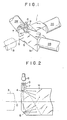
- a prism type color separation optical system 1 consisting of three prism blocks is located between a taking lens 3 of the television camera having an optical axis O and image pick up elements 2R, 2G, 2B like image pick up tubes and separates an image from the taking lens 3 into three color components or R (red), G (green) and B (blue).
- the prism type color separation optical system 1 has reflecting surfaces 4 and 5 in a part of the first prism 1a having an entrance face serving as an entrance face of the whole optical system 1.
- the reflecting surfaces 4 and 5 are formed at the upper and lower corners of the front entrance face of the first prism block 1a.
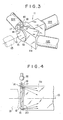
- the bias light reflected by the reflecting surfaces 14 and 15 is reflected toward the entrance face of the first prism block 11a and caused to advance in desirable paths symmetric with respect to the optical axis O of the optical system 11. Further, the light coming from' the bias light source 16 and not being reflected by the reflecting surface 14 or 15 advances within the plane parallel plate 19 totally reflected by the opposite surfaces of the plate 19 and does not advance toward the entrance face of the prism block 11a.
- the bias light not reflected by the reflecting surfaces 14 and 15 is indicated by broken lines with an arrow in Figure 4. Therefore, the bias light not reflected by the reflecting surface 14 or 15 is not received by the image pick up elements 12R, 12G, 12B. There is, therefore, no fear of nonuniform illumination of the bias light upon the image pick up elements.
- the reference numeral 18 designates a color balancing control filter as is used in the conventional color separation optical system.
Landscapes
- Engineering & Computer Science (AREA)
- Multimedia (AREA)
- Signal Processing (AREA)
- Color Television Image Signal Generators (AREA)
- Optical Elements Other Than Lenses (AREA)
Claims (6)
Applications Claiming Priority (2)
| Application Number | Priority Date | Filing Date | Title |
|---|---|---|---|
| JP21216/80 | 1980-02-22 | ||
| JP2121680A JPS56117489A (en) | 1980-02-22 | 1980-02-22 | Color separating optical system for color television camera |
Publications (2)
| Publication Number | Publication Date |
|---|---|
| EP0034812A1 EP0034812A1 (de) | 1981-09-02 |
| EP0034812B1 true EP0034812B1 (de) | 1985-06-26 |
Family
ID=12048807
Family Applications (1)
| Application Number | Title | Priority Date | Filing Date |
|---|---|---|---|
| EP81101196A Expired EP0034812B1 (de) | 1980-02-22 | 1981-02-19 | Optischer Farbenteiler für eine Farbfernsehkamera |
Country Status (4)
| Country | Link |
|---|---|
| US (1) | US4422722A (de) |
| EP (1) | EP0034812B1 (de) |
| JP (1) | JPS56117489A (de) |
| DE (1) | DE3171084D1 (de) |
Families Citing this family (12)
| Publication number | Priority date | Publication date | Assignee | Title |
|---|---|---|---|---|
| JPS58198980A (ja) * | 1982-05-15 | 1983-11-19 | Fuji Photo Optical Co Ltd | 色分解光学系 |
| JPS5997292A (ja) * | 1982-11-26 | 1984-06-05 | Victor Co Of Japan Ltd | カラ−テレビジヨン撮像装置 |
| JPS5986785U (ja) * | 1982-11-30 | 1984-06-12 | 日本ビクター株式会社 | カラ−テレビジヨン撮像素子へのバイアス光付与装置 |
| JPS5986786U (ja) * | 1982-11-30 | 1984-06-12 | 日本ビクター株式会社 | カラ−テレビジヨン撮像装置 |
| JPS61103101A (ja) * | 1984-10-26 | 1986-05-21 | Adamando Kogyo Kk | 三管式カラ−カメラ用プリズム |
| US4623221A (en) * | 1985-02-14 | 1986-11-18 | Rca Corporation | Device for providing a substantially flat light field |
| US4749259A (en) * | 1987-05-15 | 1988-06-07 | Hughes Aircraft Company | Liquid crystal image projection with multicolor prepolarizing system |
| JP2579159Y2 (ja) * | 1990-10-04 | 1998-08-20 | 旭光学工業株式会社 | 光学プリズム |
| JP3125182B2 (ja) * | 1995-06-14 | 2001-01-15 | 旭精密株式会社 | Cマウントカラーtv用色分解プリズムアッセンブリ |
| JP3676524B2 (ja) * | 1996-10-25 | 2005-07-27 | ペンタックス株式会社 | プリズム |
| FR2807342B1 (fr) * | 2000-04-07 | 2002-07-12 | Gilson Sa | Pipette de prelevement a ejecteur de cone |
| US7246551B2 (en) * | 2004-07-09 | 2007-07-24 | Protedyne Corporation | Liquid handling device with surface features at a seal |
Family Cites Families (10)
| Publication number | Priority date | Publication date | Assignee | Title |
|---|---|---|---|---|
| FR1577746A (de) * | 1967-08-31 | 1969-08-08 | ||
| DE1537130B2 (de) * | 1967-10-25 | 1974-07-18 | Robert Bosch Fernsehanlagen Gmbh, 6100 Darmstadt | Farbfernsehkamera mit verringertem Nachziehen |
| US3824004A (en) * | 1970-04-27 | 1974-07-16 | Fuji Photo Optical Co Ltd | Color separation prism for television camera |
| FR2228888A1 (en) * | 1973-05-08 | 1974-12-06 | Ici Ltd | Batch dyeing of polyester fabrics - using aq. dye dispersion contg. org. vehicle which forms azeotrope with water |
| JPS50134517A (de) * | 1974-04-10 | 1975-10-24 | ||
| US4085419A (en) * | 1975-12-08 | 1978-04-18 | Canon Kabushiki Kaisha | Color television camera |
| JPS5714467Y2 (de) * | 1976-03-30 | 1982-03-25 | ||
| JPS5733856Y2 (de) * | 1976-08-07 | 1982-07-26 | ||
| JPS53120332A (en) * | 1977-03-30 | 1978-10-20 | Fuji Photo Optical Co Ltd | Optical system of color separation prism for color television |
| JPS54104729A (en) * | 1978-02-03 | 1979-08-17 | Canon Inc | Television camera |
-
1980
- 1980-02-22 JP JP2121680A patent/JPS56117489A/ja active Pending
-
1981
- 1981-02-02 US US06/230,605 patent/US4422722A/en not_active Expired - Fee Related
- 1981-02-19 EP EP81101196A patent/EP0034812B1/de not_active Expired
- 1981-02-19 DE DE8181101196T patent/DE3171084D1/de not_active Expired
Also Published As
| Publication number | Publication date |
|---|---|
| US4422722A (en) | 1983-12-27 |
| DE3171084D1 (en) | 1985-08-01 |
| EP0034812A1 (de) | 1981-09-02 |
| JPS56117489A (en) | 1981-09-14 |
Similar Documents
| Publication | Publication Date | Title |
|---|---|---|
| US6151166A (en) | Color separation element and image display device using same | |
| US5777674A (en) | Four color separation optical device | |
| JPH01237619A (ja) | 光学装置 | |
| US4422722A (en) | Color separation optical system for color television camera | |
| US5251068A (en) | Objective lens having a filter | |
| US4161349A (en) | Beam separating prism system | |
| US5173599A (en) | Color image reading apparatus with blazed diffraction grating | |
| US4636627A (en) | Focus detecting apparatus | |
| US5689341A (en) | LCD panel test system | |
| US4084179A (en) | Color television camera | |
| EP0448708B1 (de) | Strahlteiler für farbabbildungsvorrichtung | |
| CA1208465A (en) | Camera for picking-up coloured pictures | |
| US4085419A (en) | Color television camera | |
| US5668919A (en) | Camera | |
| US4171869A (en) | Color separation prism system for color television camera | |
| JPS648806B2 (de) | ||
| US4425577A (en) | Television camera equipped with a color-separating arrangement disposed behind the objective | |
| US3696202A (en) | Optical system for a color television camera | |
| US4080624A (en) | Optical color-separation system for use in a color television camera | |
| EP0415363B1 (de) | Farbbildlesegerät | |
| JPH09116692A (ja) | 導波路型画像読み取り装置 | |
| KR790001790B1 (ko) | 몇개의 표면들이 2색층들과 근접하는 색분리 프리즘 배열 | |
| JPS61129619A (ja) | 色分解光学系 | |
| JPH0199015A (ja) | 光学系における光束の波長帯域調整機構 | |
| JPH0421255A (ja) | カラー画像読取装置 |
Legal Events
| Date | Code | Title | Description |
|---|---|---|---|
| PUAI | Public reference made under article 153(3) epc to a published international application that has entered the european phase |
Free format text: ORIGINAL CODE: 0009012 |
|
| AK | Designated contracting states |
Designated state(s): DE FR NL |
|
| 17P | Request for examination filed |
Effective date: 19811120 |
|
| DET | De: translation of patent claims | ||
| GRAA | (expected) grant |
Free format text: ORIGINAL CODE: 0009210 |
|
| AK | Designated contracting states |
Designated state(s): DE FR NL |
|
| REF | Corresponds to: |
Ref document number: 3171084 Country of ref document: DE Date of ref document: 19850801 |
|
| ET | Fr: translation filed | ||
| PLBI | Opposition filed |
Free format text: ORIGINAL CODE: 0009260 |
|
| 26 | Opposition filed |
Opponent name: BSG TECHNISCHE BERATUNGS-GESELLSCHAFT MBH Effective date: 19860324 |
|
| NLR1 | Nl: opposition has been filed with the epo |
Opponent name: BSG TECHNISCHE BERATUNGS-GESELLSCHAFT MBH |
|
| PG25 | Lapsed in a contracting state [announced via postgrant information from national office to epo] |
Ref country code: NL Effective date: 19860901 |
|
| NLV4 | Nl: lapsed or anulled due to non-payment of the annual fee | ||
| PG25 | Lapsed in a contracting state [announced via postgrant information from national office to epo] |
Ref country code: FR Free format text: LAPSE BECAUSE OF NON-PAYMENT OF DUE FEES Effective date: 19861031 |
|
| REG | Reference to a national code |
Ref country code: FR Ref legal event code: ST |
|
| RDAG | Patent revoked |
Free format text: ORIGINAL CODE: 0009271 |
|
| STAA | Information on the status of an ep patent application or granted ep patent |
Free format text: STATUS: PATENT REVOKED |
|
| 27W | Patent revoked |
Effective date: 19861116 |