EP0034734B1 - Method and apparatus for cutting and feeding packed articles from a continuous packaging strip - Google Patents
Method and apparatus for cutting and feeding packed articles from a continuous packaging strip Download PDFInfo
- Publication number
- EP0034734B1 EP0034734B1 EP81100782A EP81100782A EP0034734B1 EP 0034734 B1 EP0034734 B1 EP 0034734B1 EP 81100782 A EP81100782 A EP 81100782A EP 81100782 A EP81100782 A EP 81100782A EP 0034734 B1 EP0034734 B1 EP 0034734B1
- Authority
- EP
- European Patent Office
- Prior art keywords
- cutting rotor
- periphery
- cutting
- cutter
- long strip
- Prior art date
- Legal status (The legal status is an assumption and is not a legal conclusion. Google has not performed a legal analysis and makes no representation as to the accuracy of the status listed.)
- Expired
Links
- 238000000034 method Methods 0.000 title claims description 17
- 238000004806 packaging method and process Methods 0.000 title description 3
- 238000012856 packing Methods 0.000 claims description 4
- 239000010902 straw Substances 0.000 description 13
- 235000013361 beverage Nutrition 0.000 description 2
- 230000035622 drinking Effects 0.000 description 2
- 235000015203 fruit juice Nutrition 0.000 description 2
- 239000011111 cardboard Substances 0.000 description 1
- 230000000694 effects Effects 0.000 description 1
- 230000002452 interceptive effect Effects 0.000 description 1
- 229920006280 packaging film Polymers 0.000 description 1
- 239000012785 packaging film Substances 0.000 description 1
- 239000000123 paper Substances 0.000 description 1
Images




Classifications
-
- B—PERFORMING OPERATIONS; TRANSPORTING
- B65—CONVEYING; PACKING; STORING; HANDLING THIN OR FILAMENTARY MATERIAL
- B65B—MACHINES, APPARATUS OR DEVICES FOR, OR METHODS OF, PACKAGING ARTICLES OR MATERIALS; UNPACKING
- B65B61/00—Auxiliary devices, not otherwise provided for, for operating on sheets, blanks, webs, binding material, containers or packages
- B65B61/04—Auxiliary devices, not otherwise provided for, for operating on sheets, blanks, webs, binding material, containers or packages for severing webs, or for separating joined packages
- B65B61/06—Auxiliary devices, not otherwise provided for, for operating on sheets, blanks, webs, binding material, containers or packages for severing webs, or for separating joined packages by cutting
- B65B61/08—Auxiliary devices, not otherwise provided for, for operating on sheets, blanks, webs, binding material, containers or packages for severing webs, or for separating joined packages by cutting using rotary cutters
-
- Y—GENERAL TAGGING OF NEW TECHNOLOGICAL DEVELOPMENTS; GENERAL TAGGING OF CROSS-SECTIONAL TECHNOLOGIES SPANNING OVER SEVERAL SECTIONS OF THE IPC; TECHNICAL SUBJECTS COVERED BY FORMER USPC CROSS-REFERENCE ART COLLECTIONS [XRACs] AND DIGESTS
- Y10—TECHNICAL SUBJECTS COVERED BY FORMER USPC
- Y10S—TECHNICAL SUBJECTS COVERED BY FORMER USPC CROSS-REFERENCE ART COLLECTIONS [XRACs] AND DIGESTS
- Y10S83/00—Cutting
- Y10S83/929—Particular nature of work or product
- Y10S83/945—Separating connected articles
-
- Y—GENERAL TAGGING OF NEW TECHNOLOGICAL DEVELOPMENTS; GENERAL TAGGING OF CROSS-SECTIONAL TECHNOLOGIES SPANNING OVER SEVERAL SECTIONS OF THE IPC; TECHNICAL SUBJECTS COVERED BY FORMER USPC CROSS-REFERENCE ART COLLECTIONS [XRACs] AND DIGESTS
- Y10—TECHNICAL SUBJECTS COVERED BY FORMER USPC
- Y10T—TECHNICAL SUBJECTS COVERED BY FORMER US CLASSIFICATION
- Y10T83/00—Cutting
- Y10T83/04—Processes
- Y10T83/0524—Plural cutting steps
- Y10T83/0538—Repetitive transverse severing from leading edge of work
-
- Y—GENERAL TAGGING OF NEW TECHNOLOGICAL DEVELOPMENTS; GENERAL TAGGING OF CROSS-SECTIONAL TECHNOLOGIES SPANNING OVER SEVERAL SECTIONS OF THE IPC; TECHNICAL SUBJECTS COVERED BY FORMER USPC CROSS-REFERENCE ART COLLECTIONS [XRACs] AND DIGESTS
- Y10—TECHNICAL SUBJECTS COVERED BY FORMER USPC
- Y10T—TECHNICAL SUBJECTS COVERED BY FORMER US CLASSIFICATION
- Y10T83/00—Cutting
- Y10T83/202—With product handling means
- Y10T83/2092—Means to move, guide, or permit free fall or flight of product
- Y10T83/2096—Means to move product out of contact with tool
- Y10T83/2098—With means to effect subsequent conveying or guiding
-
- Y—GENERAL TAGGING OF NEW TECHNOLOGICAL DEVELOPMENTS; GENERAL TAGGING OF CROSS-SECTIONAL TECHNOLOGIES SPANNING OVER SEVERAL SECTIONS OF THE IPC; TECHNICAL SUBJECTS COVERED BY FORMER USPC CROSS-REFERENCE ART COLLECTIONS [XRACs] AND DIGESTS
- Y10—TECHNICAL SUBJECTS COVERED BY FORMER USPC
- Y10T—TECHNICAL SUBJECTS COVERED BY FORMER US CLASSIFICATION
- Y10T83/00—Cutting
- Y10T83/202—With product handling means
- Y10T83/2092—Means to move, guide, or permit free fall or flight of product
- Y10T83/2183—Product mover including gripper means
-
- Y—GENERAL TAGGING OF NEW TECHNOLOGICAL DEVELOPMENTS; GENERAL TAGGING OF CROSS-SECTIONAL TECHNOLOGIES SPANNING OVER SEVERAL SECTIONS OF THE IPC; TECHNICAL SUBJECTS COVERED BY FORMER USPC CROSS-REFERENCE ART COLLECTIONS [XRACs] AND DIGESTS
- Y10—TECHNICAL SUBJECTS COVERED BY FORMER USPC
- Y10T—TECHNICAL SUBJECTS COVERED BY FORMER US CLASSIFICATION
- Y10T83/00—Cutting
- Y10T83/444—Tool engages work during dwell of intermittent workfeed
- Y10T83/4607—With rotary work-carrier
-
- Y—GENERAL TAGGING OF NEW TECHNOLOGICAL DEVELOPMENTS; GENERAL TAGGING OF CROSS-SECTIONAL TECHNOLOGIES SPANNING OVER SEVERAL SECTIONS OF THE IPC; TECHNICAL SUBJECTS COVERED BY FORMER USPC CROSS-REFERENCE ART COLLECTIONS [XRACs] AND DIGESTS
- Y10—TECHNICAL SUBJECTS COVERED BY FORMER USPC
- Y10T—TECHNICAL SUBJECTS COVERED BY FORMER US CLASSIFICATION
- Y10T83/00—Cutting
- Y10T83/444—Tool engages work during dwell of intermittent workfeed
- Y10T83/463—Work-feed element contacts and moves with work
Definitions
- the invention relates to a method of cutting and feeding of continuous packages wherein a long strip of packaged, preferably stick-shaped, articles, at regular intervals between connected parts successively fed out, is conveyed to a cutting rotor performing intermittent rotation, the above-mentioned long strip of articles being held to the periphery of said cutting rotor and cut into individual packages at the connected parts by means of a cutter, and this separated package is taken out of the periphery of the cutting rotor by a holding device.
- a preferred field of application of the invention is a method and apparatus for cutting single packed drinking straws from a continuous strip on which the straws are packed parallel to each other between two continuous webs of packaging film, and for feeding the single packed straws to a station where they can be applied to other articles, such as beverage containers.
- a method and apparatus of the aforementioned kind is known.
- the strip is held to the periphery of the cutting rotor by means of a guide rail which extends round the periphery of the cutting rotor. Since the cutter of this device is disposed on the outside of the cutting rotor this guide rail interferes with the cutting device. Therefore the knife element of the known device shows a yoke carrying two knives spaced at a distance from one another.
- This known device has the disadvantage that it is impossible to cut the whole width of the strip because of the interfering guide rail. Therefore the drinking straws or the like are interconnected only by band or strip parts having a width less than the width of the two knives.
- This object is solved according to the invention by a method for cutting and feeding of the aforementioned kind which is characterized in that the strip D is held by vacuum to the periphery of the cutting rotor and that the cutter rotates on its axis, revolving at the same time about a parallel axis and passing through said long strip of article D into notched grooves on the periphery of said cutting rotor.
- the apparatus for performing the method according to the invention wherein the cutting rotor performing an intermittent rotation is equipped at its periphery with the notched grooves parallel to its shaft and wherein the cutter is disposed on the outside of said cutting rotor is characterized in that the cutting rotor is disposed on the outside of a feed roller by which the long strip of article D packing the stick-shaped articles at regular intervals is fed out one pitch at a time, that the front part anc' rear part of the grooves on the periphery of th cutting rotor are acted on by a vacuum force and that the cutter revolving, while rotating on its axis at the same time, is disposed to pass into the above mentioned notched grooves, and that each package cut off by the cutter is received between two legs of one of a plurality of holding devices and conveyed at intervals larger than one pitch of the above mentioned long strip of article D.
- the preferred field of use of the application is related to a packaging container made of paper card board or the like for a beverage, such as fruit juice, as shown in Fig. 10.
- a straw B as a fitting is attached to said container A. It is usual for sanitary reasons that said straw is packed.
- the most effective packing method of said straws B employs a process in which two long strips of film C, and C 2 of continuous lengths, automatically fed out, are used for packing the abovementioned straws B at regular intervals in a widthwise direction of these two films, one over the other between one straw and the adjacent straw, which are melt-welded so as to produce a long strip of article D as shown in Fig. 9 and, after that, a package F in which each of the packed straws is taken out by means of cutting the long strip of article D into pieces at the abovementioned space between connected parts E.
- the present invention relates to a process in which the long strip of article D continuously packs a number of stick-shaped articles B, such as straws, therein and is being successively taken out, the long strip or article D is cut into pieces at the connected parts E so as to produce packages F one by one, and each of packages F is arranged to be supplied to a subsequent process.
- a hold-down roller 1 is perpendicularly equipped at its outer side with a feed roller 2 which can feed out the long strip of article D one pitch at a time (namely, the distance between a stick-shaped article B and a successive stick-shaped article B in the long strip of article D) by means of the intermittent rotation thereof at the time when a signal is given, and at the periphery of said feed roller 2 a plurality of grooves 2a are formed at regular intervals in parallel to the central shaft thereof. At this point each of the regular intervals is equal to the distance between a stick-shaped article B and a successive stick-shaped article B, and the parts d expanded out of the bottom in Fig. 9 is one by one housed in each of said grooves 2a.
- the feed roller 2, shown in Figs. 1, 5 and 8, is arranged to be counterclockwise rotated.
- the feed roller 2 is perpendicularly equipped at its outer side with a cutting rotor 3 which performs such an intermittent rotation that said cutting rotor 3 is gradually accelerated to some extent and then is gradually decelerated, finally stopping, and at the periphery of said cutting rotor 3 a plurality of notched grooves 3a are formed at regular intervals in parallel to the central shaft. At this point each of the regular intervals is spaced more largely than the distance between a packed long strip of article D and a successive packed one. There exist six notched grooves 3a according to the example illustrated by the figure.
- the cutting rotor 3, shown in Fig. 1, 5 and 8, is arranged to be rotated clockwise.
- the cutting rotor 3 and the feed roller 2 are synchronously rotated.
- a plurality of holes 3b (Fig. 2) corresponding to each of the notched grooves 3a are formed one by one in a concyclic manner. Said holes 3b are communicated with the periphery of the cutting rotor 3 before and behind the respective corresponding notched grooves 3a by small holes 3c and small holes 3d.
- the lower surface of the cutting rotor 3 is faced with a fixed disk 4 (Fig. 4).
- the left half portion of the surface of this disk 4 is equipped with a semi-circular portion of groove 4a at the position corresponding to each of the holes 3b in the cutting rotor 3.
- the groove 4a is communicated with a vacuum device (not shown), whereby when the holes 3b are located on the groove 4a, a vacuum force acts through the small holes 3c and 3d on the periphery of the cutting rotor 3 before and behind the notched grooves 3a.
- the outer part of the cutting rotor 3 is equipped with a cutter which can rotate on its axis, revolving in a vertical direction at the same time.
- the cutter 5 passes vertically in the notched grooves 3a at the periphery of the cutting rotor 3 which stops by means of the revolution thereof.
- a rotary plate 9 is freely fitted on a shaft 8 to which the turning force of a motor 7 is transmitted through a belt 6.
- a sprocket 10 fixed on said rotary plate 9 and a chain 11 thrown around said sprocket 10 enable said rotary plate 9 to separately rotate around the shaft 8 as center.
- the cutter 5 is rotatably mounted on the front surface of the rotary plate 9. Said cutter 5 is arranged to be connected to the turning force of the shaft 8 by a belt 12.
- An up-and-down pair of endless chains 13 (Fig. 1 and 4) is disposed closely to the outer side of the cutting rotor 3 (located at the upper side of the space in Fig. 1). Said chains 13 are equipped at regular intervals with a holding device 14.
- the holding device 14 is formed by lockably fitting two holding pieces to longitudinally- directed pins 15 and 15 of which both ends are fixed to the up-and-down chains 13 and 13.
- a projecting piece 14b of the holding piece 14a coincides with a guide 16 provided within the chain 13
- the legs of the holding device 14 straddle as if a mouth is opened like 14a' shown in Fig. 4 and when the projecting piece 14b does not coincide with the guide 16, said legs are closed, thereby putting the above- mentioned package F between both holding pieces.
- the method introduced by the present invention there is an effect of automatically and effectively performing the work in which the long strip of article containing stick-shaped articles at regular intervals is cut off into pieces and, subsequently, taken out.
- the apparatus introduced by the present invention is used, the above-mentioned work can be sequentially performed.
Landscapes
- Engineering & Computer Science (AREA)
- Mechanical Engineering (AREA)
- Auxiliary Devices For And Details Of Packaging Control (AREA)
- Basic Packing Technique (AREA)
Description
- The invention relates to a method of cutting and feeding of continuous packages wherein a long strip of packaged, preferably stick-shaped, articles, at regular intervals between connected parts successively fed out, is conveyed to a cutting rotor performing intermittent rotation, the above-mentioned long strip of articles being held to the periphery of said cutting rotor and cut into individual packages at the connected parts by means of a cutter, and this separated package is taken out of the periphery of the cutting rotor by a holding device. A preferred field of application of the invention is a method and apparatus for cutting single packed drinking straws from a continuous strip on which the straws are packed parallel to each other between two continuous webs of packaging film, and for feeding the single packed straws to a station where they can be applied to other articles, such as beverage containers.
- From GB-A-2 013 606 a method and apparatus of the aforementioned kind is known. In this known cutting and feeding device the strip is held to the periphery of the cutting rotor by means of a guide rail which extends round the periphery of the cutting rotor. Since the cutter of this device is disposed on the outside of the cutting rotor this guide rail interferes with the cutting device. Therefore the knife element of the known device shows a yoke carrying two knives spaced at a distance from one another.
- This known device has the disadvantage that it is impossible to cut the whole width of the strip because of the interfering guide rail. Therefore the drinking straws or the like are interconnected only by band or strip parts having a width less than the width of the two knives.
- It is therefore the object of the invention to provide a method and apparatus of the aforementioned kind by which the cutting of the packaged articles from the continuous strip and the feeding of the single articles to a further processing station can be effected in a simple reliable and effective manner which provides the possibility of an exact matching of the feeding of the articles to the time sequence required by the following processing station.
- This object is solved according to the invention by a method for cutting and feeding of the aforementioned kind which is characterized in that the strip D is held by vacuum to the periphery of the cutting rotor and that the cutter rotates on its axis, revolving at the same time about a parallel axis and passing through said long strip of article D into notched grooves on the periphery of said cutting rotor.
- The apparatus for performing the method according to the invention wherein the cutting rotor performing an intermittent rotation is equipped at its periphery with the notched grooves parallel to its shaft and wherein the cutter is disposed on the outside of said cutting rotor is characterized in that the cutting rotor is disposed on the outside of a feed roller by which the long strip of article D packing the stick-shaped articles at regular intervals is fed out one pitch at a time, that the front part anc' rear part of the grooves on the periphery of th cutting rotor are acted on by a vacuum force and that the cutter revolving, while rotating on its axis at the same time, is disposed to pass into the above mentioned notched grooves, and that each package cut off by the cutter is received between two legs of one of a plurality of holding devices and conveyed at intervals larger than one pitch of the above mentioned long strip of article D.
- A preferred embodiment of the invention will be described with reference to the accompanying drawings in which
- Fig. 1 is a general view of an embodiment of the apparatus for cutting and feeding packed articles from a continuous packaging strip;
- Fig. 2 is an enlarged transverse sectional view of a cutting rotor;
- Fig. 3 is a front view of a cutter's driving mechanism;
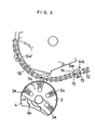
- Fig. 4 is an enlarged plan view of the process of taking out a package which is held by a vacuum on the periphery of the cutting rotor by a holding device;
- Figs 5 to 8 are plan views illustrating actuating conditions in the order of processes;
- Fig. 9 is a perspective view of a long strip of articles in which stick-shaped articles are successively packed, illustrating that the lead portion of the long strip of article is in the state of being cut off; and
- Fig. 10 is a perspective view illustrating one example of how a packed stick-shaped article (straw) is actually used.
- The preferred field of use of the application is related to a packaging container made of paper card board or the like for a beverage, such as fruit juice, as shown in Fig. 10.
- In marketing fruit juice or the like contained in such container A, a straw B as a fitting is attached to said container A. It is usual for sanitary reasons that said straw is packed.
- The most effective packing method of said straws B employs a process in which two long strips of film C, and C2 of continuous lengths, automatically fed out, are used for packing the abovementioned straws B at regular intervals in a widthwise direction of these two films, one over the other between one straw and the adjacent straw, which are melt-welded so as to produce a long strip of article D as shown in Fig. 9 and, after that, a package F in which each of the packed straws is taken out by means of cutting the long strip of article D into pieces at the abovementioned space between connected parts E.
- The present invention relates to a process in which the long strip of article D continuously packs a number of stick-shaped articles B, such as straws, therein and is being successively taken out, the long strip or article D is cut into pieces at the connected parts E so as to produce packages F one by one, and each of packages F is arranged to be supplied to a subsequent process.
- A hold-
down roller 1 is perpendicularly equipped at its outer side with afeed roller 2 which can feed out the long strip of article D one pitch at a time (namely, the distance between a stick-shaped article B and a successive stick-shaped article B in the long strip of article D) by means of the intermittent rotation thereof at the time when a signal is given, and at the periphery of saidfeed roller 2 a plurality ofgrooves 2a are formed at regular intervals in parallel to the central shaft thereof. At this point each of the regular intervals is equal to the distance between a stick-shaped article B and a successive stick-shaped article B, and the parts d expanded out of the bottom in Fig. 9 is one by one housed in each of saidgrooves 2a. Thefeed roller 2, shown in Figs. 1, 5 and 8, is arranged to be counterclockwise rotated. - The
feed roller 2 is perpendicularly equipped at its outer side with acutting rotor 3 which performs such an intermittent rotation that saidcutting rotor 3 is gradually accelerated to some extent and then is gradually decelerated, finally stopping, and at the periphery of said cuttingrotor 3 a plurality of notchedgrooves 3a are formed at regular intervals in parallel to the central shaft. At this point each of the regular intervals is spaced more largely than the distance between a packed long strip of article D and a successive packed one. There exist sixnotched grooves 3a according to the example illustrated by the figure. Thecutting rotor 3, shown in Fig. 1, 5 and 8, is arranged to be rotated clockwise. - The
cutting rotor 3 and thefeed roller 2 are synchronously rotated. - At the positions corresponding to the innermost recess of the
notched grooves 3a at the inner part of thecutting rotor 3 a plurality ofholes 3b (Fig. 2) corresponding to each of thenotched grooves 3a are formed one by one in a concyclic manner. Saidholes 3b are communicated with the periphery of thecutting rotor 3 before and behind the respective corresponding notchedgrooves 3a bysmall holes 3c andsmall holes 3d. - The lower surface of the
cutting rotor 3 is faced with a fixed disk 4 (Fig. 4). The left half portion of the surface of this disk 4 is equipped with a semi-circular portion of groove 4a at the position corresponding to each of theholes 3b in thecutting rotor 3. The groove 4a is communicated with a vacuum device (not shown), whereby when theholes 3b are located on the groove 4a, a vacuum force acts through thesmall holes cutting rotor 3 before and behind thenotched grooves 3a. - The outer part of the
cutting rotor 3 is equipped with a cutter which can rotate on its axis, revolving in a vertical direction at the same time. Thecutter 5 passes vertically in thenotched grooves 3a at the periphery of thecutting rotor 3 which stops by means of the revolution thereof. - Here is now shown an example of the mechanism in which the
cutter 5 rotates on its axis, revolving at the same time; arotary plate 9 is freely fitted on ashaft 8 to which the turning force of amotor 7 is transmitted through abelt 6. Asprocket 10 fixed on saidrotary plate 9 and achain 11 thrown around saidsprocket 10 enable saidrotary plate 9 to separately rotate around theshaft 8 as center. - The
cutter 5 is rotatably mounted on the front surface of therotary plate 9. Saidcutter 5 is arranged to be connected to the turning force of theshaft 8 by abelt 12. - An up-and-down pair of endless chains 13 (Fig. 1 and 4) is disposed closely to the outer side of the cutting rotor 3 (located at the upper side of the space in Fig. 1). Said
chains 13 are equipped at regular intervals with aholding device 14. - The
holding device 14 is formed by lockably fitting two holding pieces to longitudinally- directedpins down chains piece 14b of theholding piece 14a coincides with aguide 16 provided within thechain 13, the legs of theholding device 14 straddle as if a mouth is opened like 14a' shown in Fig. 4 and when the projectingpiece 14b does not coincide with theguide 16, said legs are closed, thereby putting the above- mentioned package F between both holding pieces. - At this moment the
cutter 5 which continues to revolve, rotating on its axis at the same time descends from the upper part and, as shown in Fig. 6, passes into anotched groove 3a, on thecutting rotor 3 thereby cutting the first connected part E. As a result one package F, containing one stick-shaped article is cut off and this package F, is held by vacuum without falling down on the periphery of thecutting rotor 3 in front of thenotched groove 3a, by a vacuum force out of thesmall hole 3d. As shown in Fig. 7, said package F which is still held by vacuum on the periphery thereof is conveyed by the rotation of thecutting rotor 3. - When said package F, is conveyed to a position as shown in Fig. 8, the holding device mounted on the
chain 13 travelling at the fixed speed, continues to straddle as if the mouth is opened like 14a' shown in Fig. 4 and, at the same time, makes an access to the periphery of thecutting rotor 3, and the projectingpiece 14b of anotherholding piece 14a, as soon as it comes off theguide 16 its legs shall be closed. At this moment, as shown in Fig. 8, the package F, held by vacuum on the periphery of thecutting rotor 3 is put between both holding pieces, and then this package F, which is still held between the two parts of theholding device 14 is fed by the travelling ofchain 13 in an arrow direction as shown in Fig. 8. - At the moment when the cut-off package is put between the two parts of the
holding device 14, the vacuum force does not act on the periphery of thecutting rotor 3 to which said package was held by vacuum. That is because thehole 3b corresponding to said part comes off the end part of the groove 4a of the disk 4, whereby the vacuum force cannot act on thehole 3b. - Under the circumstances as shown in Fig. 7 when the subsequent stick-shaped article B comes out by one article in front of the following
notched groove 3a2 on thecutting rotor 3, similar to the previous case, thecutter 5 which revolves, rotating on its axis at the same time passes into saidnotched groove 3a2 thereby cutting the following connected part E so as to produce a package F2. - By means of repeating this operation while the long strip of article in which the stick-shaped articles are packed at regular intervals being successively (by 1 pitch at a time) fed out, each of them is cut off one by one so that the separated packages are successively conveyed at larger intervals than 1 pitch of the long strip of article to the following working process by the holding device.
- Since when the
feed roller 2 is not given the signal, saidfeed roller 2 stops, even if thecutting rotor 3 rotates, the long strip of article D held by vacuum to the periphery thereof only slides on the periphery of thecutting rotor 3 without being taken out, coupled with that said long strip of article D is pressed against the side of thefeed roller 2 by the hold-down roller 1. For this reason even when thecutting rotor 3 stops and thecutter 5 which revolves, rotating on its axis at the same time passes into thenotched grooves 3a, the long strip of article D is not erroneously cut off. - According to the method introduced by the present invention, there is an effect of automatically and effectively performing the work in which the long strip of article containing stick-shaped articles at regular intervals is cut off into pieces and, subsequently, taken out. When the apparatus introduced by the present invention is used, the above-mentioned work can be sequentially performed.
Claims (2)
Applications Claiming Priority (2)
| Application Number | Priority Date | Filing Date | Title |
|---|---|---|---|
| JP21995/80 | 1980-02-22 | ||
| JP55021995A JPS5810293B2 (en) | 1980-02-22 | 1980-02-22 | Method and device for cutting and supplying continuous packages |
Publications (2)
| Publication Number | Publication Date |
|---|---|
| EP0034734A1 EP0034734A1 (en) | 1981-09-02 |
| EP0034734B1 true EP0034734B1 (en) | 1984-05-23 |
Family
ID=12070597
Family Applications (1)
| Application Number | Title | Priority Date | Filing Date |
|---|---|---|---|
| EP81100782A Expired EP0034734B1 (en) | 1980-02-22 | 1981-02-04 | Method and apparatus for cutting and feeding packed articles from a continuous packaging strip |
Country Status (7)
| Country | Link |
|---|---|
| US (1) | US4362075A (en) |
| EP (1) | EP0034734B1 (en) |
| JP (1) | JPS5810293B2 (en) |
| AU (1) | AU541003B2 (en) |
| BR (1) | BR8101042A (en) |
| CA (1) | CA1162841A (en) |
| DE (1) | DE3163700D1 (en) |
Families Citing this family (13)
| Publication number | Priority date | Publication date | Assignee | Title |
|---|---|---|---|---|
| JPS58216530A (en) * | 1982-05-27 | 1983-12-16 | 十條製紙株式会社 | Straw fixture |
| JPS5962113A (en) * | 1982-09-30 | 1984-04-09 | Matsushita Electric Works Ltd | Preparation of multi-layered board |
| JPS59124249A (en) * | 1982-12-24 | 1984-07-18 | エービー テトラパック | Device for delivering beltlike continuous package |
| JPS6171994A (en) * | 1984-09-12 | 1986-04-12 | エービー テトラパック | Cutter for beltlike continuous package |
| SE468983B (en) * | 1987-01-22 | 1993-04-26 | Profor Ab | TRANSPORT UNIT |
| SE463970B (en) * | 1987-03-24 | 1991-02-18 | Roby Teknik Ab | SUGROERSFOERPACKNING |
| SE468008B (en) * | 1991-02-01 | 1992-10-19 | Tetra Alfa Holdings | DEVICE FOR THE CONTROL OF COUNTRY CONNECTED FORMS IN APPLICATION TO PACKAGING CONTAINERS |
| GB2293134A (en) * | 1994-11-10 | 1996-03-20 | Grace W R & Co | Supply of fitments on a flexible tape |
| DE19745855C2 (en) * | 1997-10-16 | 2002-06-20 | Indag Gmbh | Drinking straw attachment device and method for attaching drinking straws to beverage film bags |
| DE102017109118A1 (en) * | 2017-04-27 | 2018-10-31 | Sig Technology Ag | Application device and method for applying additional elements in an application orientation |
| CN111002638B (en) * | 2019-12-16 | 2025-07-04 | 咸宁职业技术学院 | A conjoined chip small cloth bag rotating separation system |
| CN112793826A (en) * | 2021-01-27 | 2021-05-14 | 杨祥贵 | Make things convenient for fruit grower to carry out automatic packing plant of fruit of packing one by one |
| CN114476197A (en) * | 2022-03-11 | 2022-05-13 | 重庆市天实精工科技有限公司 | Camera module pad pasting assembly and camera module pad pasting dyestripping equipment |
Family Cites Families (5)
| Publication number | Priority date | Publication date | Assignee | Title |
|---|---|---|---|---|
| US3057528A (en) * | 1960-09-21 | 1962-10-09 | Ibm | Component delivery and cutoff apparatus |
| US3586586A (en) * | 1969-12-15 | 1971-06-22 | Jack V Berg | Tape applicating and severing means |
| US3903768A (en) * | 1971-12-20 | 1975-09-09 | Owens Illinois Inc | Machine for producing a plastic-covered glass container |
| DE2344989A1 (en) * | 1973-09-06 | 1975-07-24 | Verpa Anstalt | Machine for transverse separation of continuous packing film - has an eccentrically driven semicircular triangular or square cutter |
| SE424847B (en) * | 1978-01-30 | 1982-08-16 | Tetra Pak Int | MACHINE FOR APPLICATION OF SUGROR ON PACKAGING CONTAINER |
-
1980
- 1980-02-22 JP JP55021995A patent/JPS5810293B2/en not_active Expired
-
1981
- 1981-02-04 EP EP81100782A patent/EP0034734B1/en not_active Expired
- 1981-02-04 DE DE8181100782T patent/DE3163700D1/en not_active Expired
- 1981-02-16 CA CA000370933A patent/CA1162841A/en not_active Expired
- 1981-02-17 US US06/235,088 patent/US4362075A/en not_active Expired - Lifetime
- 1981-02-20 AU AU67512/81A patent/AU541003B2/en not_active Ceased
- 1981-02-20 BR BR8101042A patent/BR8101042A/en not_active IP Right Cessation
Also Published As
| Publication number | Publication date |
|---|---|
| BR8101042A (en) | 1981-08-25 |
| JPS5810293B2 (en) | 1983-02-25 |
| DE3163700D1 (en) | 1984-06-28 |
| AU541003B2 (en) | 1984-12-13 |
| EP0034734A1 (en) | 1981-09-02 |
| JPS56131136A (en) | 1981-10-14 |
| US4362075A (en) | 1982-12-07 |
| AU6751281A (en) | 1981-08-27 |
| CA1162841A (en) | 1984-02-28 |
Similar Documents
| Publication | Publication Date | Title |
|---|---|---|
| EP0035645B1 (en) | Method of and apparatus for securing an article to a container | |
| EP0034734A1 (en) | Method and apparatus for cutting and feeding packed articles from a continuous packaging strip | |
| US4338768A (en) | Automatic machine for sorting items of correspondence, particularly magazines, into batches each having a different general destination | |
| EP1042172B1 (en) | An apparatus for applying drinking straws | |
| US3988875A (en) | Apparatus for producing and packaging food chips | |
| US6526725B1 (en) | Apparatus and method for attaching straws to containers | |
| US6732498B2 (en) | Vacuum assisted cut-and-seal apparatus with transfer wheel | |
| IE47986B1 (en) | Improvements in and relating to the attachment of tubes to packaging containers | |
| EP0022595A1 (en) | Machine for wrapping elongated articles in plastic film | |
| US3848725A (en) | Driven-article dropping machine and method | |
| US4372797A (en) | Method for the application of suction tubes to packing containers | |
| US3394798A (en) | Method of and apparatus for dispensing packaged articles | |
| US3877205A (en) | Packing machine | |
| US20040065212A1 (en) | Kebab machine | |
| US3566732A (en) | Vending machine | |
| US4002255A (en) | Recovery of a commodity from a sachet or bag containing the commodity | |
| US3757620A (en) | Cutting apparatus | |
| US5829954A (en) | Rotary motion feeder | |
| JPH056303Y2 (en) | ||
| US5752365A (en) | Apparatus and methods for inserting premium items | |
| US4455902A (en) | Apparatus for parting-off pieces, particularly candy, from a strand of material, particularly a soft plastic strand of material | |
| EP0118289A3 (en) | Method and apparatus for use in de-packaging packaged goods | |
| US2634893A (en) | Apparatus for filling cans | |
| US5870882A (en) | System for automatically opening cartons and removing packages therein | |
| KR850000192B1 (en) | Cutting equipment for continuous packaging |
Legal Events
| Date | Code | Title | Description |
|---|---|---|---|
| PUAI | Public reference made under article 153(3) epc to a published international application that has entered the european phase |
Free format text: ORIGINAL CODE: 0009012 |
|
| AK | Designated contracting states |
Designated state(s): CH DE FR GB IT NL SE |
|
| 17P | Request for examination filed |
Effective date: 19811030 |
|
| ITF | It: translation for a ep patent filed | ||
| GRAA | (expected) grant |
Free format text: ORIGINAL CODE: 0009210 |
|
| AK | Designated contracting states |
Designated state(s): CH DE FR GB IT LI NL SE |
|
| REF | Corresponds to: |
Ref document number: 3163700 Country of ref document: DE Date of ref document: 19840628 |
|
| ET | Fr: translation filed | ||
| PLBE | No opposition filed within time limit |
Free format text: ORIGINAL CODE: 0009261 |
|
| STAA | Information on the status of an ep patent application or granted ep patent |
Free format text: STATUS: NO OPPOSITION FILED WITHIN TIME LIMIT |
|
| 26N | No opposition filed | ||
| ITTA | It: last paid annual fee | ||
| EAL | Se: european patent in force in sweden |
Ref document number: 81100782.2 |
|
| PGFP | Annual fee paid to national office [announced via postgrant information from national office to epo] |
Ref country code: SE Payment date: 19980120 Year of fee payment: 18 |
|
| PGFP | Annual fee paid to national office [announced via postgrant information from national office to epo] |
Ref country code: NL Payment date: 19980121 Year of fee payment: 18 Ref country code: FR Payment date: 19980121 Year of fee payment: 18 |
|
| PGFP | Annual fee paid to national office [announced via postgrant information from national office to epo] |
Ref country code: DE Payment date: 19980123 Year of fee payment: 18 |
|
| PGFP | Annual fee paid to national office [announced via postgrant information from national office to epo] |
Ref country code: CH Payment date: 19980126 Year of fee payment: 18 |
|
| PGFP | Annual fee paid to national office [announced via postgrant information from national office to epo] |
Ref country code: GB Payment date: 19980127 Year of fee payment: 18 |
|
| PG25 | Lapsed in a contracting state [announced via postgrant information from national office to epo] |
Ref country code: GB Free format text: LAPSE BECAUSE OF NON-PAYMENT OF DUE FEES Effective date: 19990204 |
|
| PG25 | Lapsed in a contracting state [announced via postgrant information from national office to epo] |
Ref country code: SE Free format text: LAPSE BECAUSE OF NON-PAYMENT OF DUE FEES Effective date: 19990205 |
|
| PG25 | Lapsed in a contracting state [announced via postgrant information from national office to epo] |
Ref country code: LI Free format text: LAPSE BECAUSE OF NON-PAYMENT OF DUE FEES Effective date: 19990228 Ref country code: CH Free format text: LAPSE BECAUSE OF NON-PAYMENT OF DUE FEES Effective date: 19990228 |
|
| PG25 | Lapsed in a contracting state [announced via postgrant information from national office to epo] |
Ref country code: NL Free format text: LAPSE BECAUSE OF NON-PAYMENT OF DUE FEES Effective date: 19990901 |
|
| GBPC | Gb: european patent ceased through non-payment of renewal fee |
Effective date: 19990204 |
|
| REG | Reference to a national code |
Ref country code: CH Ref legal event code: PL |
|
| PG25 | Lapsed in a contracting state [announced via postgrant information from national office to epo] |
Ref country code: FR Free format text: LAPSE BECAUSE OF NON-PAYMENT OF DUE FEES Effective date: 19991029 |
|
| EUG | Se: european patent has lapsed |
Ref document number: 81100782.2 |
|
| PG25 | Lapsed in a contracting state [announced via postgrant information from national office to epo] |
Ref country code: DE Free format text: LAPSE BECAUSE OF NON-PAYMENT OF DUE FEES Effective date: 19991201 |
|
| REG | Reference to a national code |
Ref country code: FR Ref legal event code: ST |