EP0034396A1 - Procédé pour contrôler la gestion énergétique d'un système énergétique et un système énergétique basé sur cette méthode - Google Patents
Procédé pour contrôler la gestion énergétique d'un système énergétique et un système énergétique basé sur cette méthode Download PDFInfo
- Publication number
- EP0034396A1 EP0034396A1 EP81200197A EP81200197A EP0034396A1 EP 0034396 A1 EP0034396 A1 EP 0034396A1 EP 81200197 A EP81200197 A EP 81200197A EP 81200197 A EP81200197 A EP 81200197A EP 0034396 A1 EP0034396 A1 EP 0034396A1
- Authority
- EP
- European Patent Office
- Prior art keywords
- heat
- temperature
- collector
- heat capacity
- recovery circuit
- Prior art date
- Legal status (The legal status is an assumption and is not a legal conclusion. Google has not performed a legal analysis and makes no representation as to the accuracy of the status listed.)
- Granted
Links
- 238000000034 method Methods 0.000 title claims abstract description 42
- 230000004907 flux Effects 0.000 claims abstract description 109
- 238000011084 recovery Methods 0.000 claims abstract description 75
- 239000012530 fluid Substances 0.000 claims abstract description 52
- 230000005855 radiation Effects 0.000 claims description 21
- 230000006870 function Effects 0.000 claims description 11
- 238000001514 detection method Methods 0.000 claims description 6
- 239000013529 heat transfer fluid Substances 0.000 claims description 6
- 230000003247 decreasing effect Effects 0.000 claims description 5
- 238000009826 distribution Methods 0.000 claims description 5
- 238000004364 calculation method Methods 0.000 claims description 4
- 230000001419 dependent effect Effects 0.000 claims description 3
- 230000002708 enhancing effect Effects 0.000 claims description 3
- 230000003292 diminished effect Effects 0.000 claims description 2
- 230000002250 progressing effect Effects 0.000 claims description 2
- 230000000630 rising effect Effects 0.000 claims description 2
- 238000003860 storage Methods 0.000 description 11
- XLYOFNOQVPJJNP-UHFFFAOYSA-N water Substances O XLYOFNOQVPJJNP-UHFFFAOYSA-N 0.000 description 9
- 230000006978 adaptation Effects 0.000 description 7
- 238000010586 diagram Methods 0.000 description 7
- 238000010438 heat treatment Methods 0.000 description 7
- 238000013517 stratification Methods 0.000 description 7
- 238000011161 development Methods 0.000 description 5
- 230000018109 developmental process Effects 0.000 description 5
- 238000000926 separation method Methods 0.000 description 5
- 230000008859 change Effects 0.000 description 4
- 230000007423 decrease Effects 0.000 description 4
- 230000001276 controlling effect Effects 0.000 description 3
- 238000007667 floating Methods 0.000 description 3
- 239000007798 antifreeze agent Substances 0.000 description 2
- 230000008901 benefit Effects 0.000 description 2
- 238000001816 cooling Methods 0.000 description 2
- 238000004519 manufacturing process Methods 0.000 description 2
- 238000005259 measurement Methods 0.000 description 2
- 238000012986 modification Methods 0.000 description 2
- 230000004048 modification Effects 0.000 description 2
- 238000004393 prognosis Methods 0.000 description 2
- 230000009291 secondary effect Effects 0.000 description 2
- 239000007787 solid Substances 0.000 description 2
- 239000000126 substance Substances 0.000 description 2
- 239000008399 tap water Substances 0.000 description 2
- 235000020679 tap water Nutrition 0.000 description 2
- 238000012546 transfer Methods 0.000 description 2
- 238000004458 analytical method Methods 0.000 description 1
- 230000006399 behavior Effects 0.000 description 1
- 235000021152 breakfast Nutrition 0.000 description 1
- 238000006243 chemical reaction Methods 0.000 description 1
- 238000011217 control strategy Methods 0.000 description 1
- 230000008878 coupling Effects 0.000 description 1
- 238000010168 coupling process Methods 0.000 description 1
- 238000005859 coupling reaction Methods 0.000 description 1
- 238000005520 cutting process Methods 0.000 description 1
- 230000006866 deterioration Effects 0.000 description 1
- 238000006073 displacement reaction Methods 0.000 description 1
- 235000020188 drinking water Nutrition 0.000 description 1
- 239000003651 drinking water Substances 0.000 description 1
- 230000000694 effects Effects 0.000 description 1
- 238000005516 engineering process Methods 0.000 description 1
- 230000001747 exhibiting effect Effects 0.000 description 1
- 238000002474 experimental method Methods 0.000 description 1
- 239000011521 glass Substances 0.000 description 1
- 230000003760 hair shine Effects 0.000 description 1
- 230000017525 heat dissipation Effects 0.000 description 1
- 239000011810 insulating material Substances 0.000 description 1
- 238000009413 insulation Methods 0.000 description 1
- 230000001788 irregular Effects 0.000 description 1
- 230000003287 optical effect Effects 0.000 description 1
- 238000002360 preparation method Methods 0.000 description 1
- 230000008569 process Effects 0.000 description 1
- 239000010453 quartz Substances 0.000 description 1
- 230000001105 regulatory effect Effects 0.000 description 1
- 238000009877 rendering Methods 0.000 description 1
- 230000000717 retained effect Effects 0.000 description 1
- 230000033764 rhythmic process Effects 0.000 description 1
- 150000003839 salts Chemical class 0.000 description 1
- 239000004065 semiconductor Substances 0.000 description 1
- VYPSYNLAJGMNEJ-UHFFFAOYSA-N silicon dioxide Inorganic materials O=[Si]=O VYPSYNLAJGMNEJ-UHFFFAOYSA-N 0.000 description 1
- 230000003595 spectral effect Effects 0.000 description 1
- 239000004575 stone Substances 0.000 description 1
- 230000001360 synchronised effect Effects 0.000 description 1
- 229920003002 synthetic resin Polymers 0.000 description 1
- 239000000057 synthetic resin Substances 0.000 description 1
- 230000036962 time dependent Effects 0.000 description 1
- 230000000007 visual effect Effects 0.000 description 1
- 238000005406 washing Methods 0.000 description 1
- 239000002699 waste material Substances 0.000 description 1
Images

Classifications
-
- F—MECHANICAL ENGINEERING; LIGHTING; HEATING; WEAPONS; BLASTING
- F28—HEAT EXCHANGE IN GENERAL
- F28D—HEAT-EXCHANGE APPARATUS, NOT PROVIDED FOR IN ANOTHER SUBCLASS, IN WHICH THE HEAT-EXCHANGE MEDIA DO NOT COME INTO DIRECT CONTACT
- F28D20/00—Heat storage plants or apparatus in general; Regenerative heat-exchange apparatus not covered by groups F28D17/00 or F28D19/00
- F28D20/0034—Heat storage plants or apparatus in general; Regenerative heat-exchange apparatus not covered by groups F28D17/00 or F28D19/00 using liquid heat storage material
- F28D20/0039—Heat storage plants or apparatus in general; Regenerative heat-exchange apparatus not covered by groups F28D17/00 or F28D19/00 using liquid heat storage material with stratification of the heat storage material
-
- F—MECHANICAL ENGINEERING; LIGHTING; HEATING; WEAPONS; BLASTING
- F24—HEATING; RANGES; VENTILATING
- F24D—DOMESTIC- OR SPACE-HEATING SYSTEMS, e.g. CENTRAL HEATING SYSTEMS; DOMESTIC HOT-WATER SUPPLY SYSTEMS; ELEMENTS OR COMPONENTS THEREFOR
- F24D11/00—Central heating systems using heat accumulated in storage masses
- F24D11/002—Central heating systems using heat accumulated in storage masses water heating system
- F24D11/003—Central heating systems using heat accumulated in storage masses water heating system combined with solar energy
-
- F—MECHANICAL ENGINEERING; LIGHTING; HEATING; WEAPONS; BLASTING
- F24—HEATING; RANGES; VENTILATING
- F24D—DOMESTIC- OR SPACE-HEATING SYSTEMS, e.g. CENTRAL HEATING SYSTEMS; DOMESTIC HOT-WATER SUPPLY SYSTEMS; ELEMENTS OR COMPONENTS THEREFOR
- F24D19/00—Details
- F24D19/10—Arrangement or mounting of control or safety devices
- F24D19/1006—Arrangement or mounting of control or safety devices for water heating systems
- F24D19/1009—Arrangement or mounting of control or safety devices for water heating systems for central heating
- F24D19/1042—Arrangement or mounting of control or safety devices for water heating systems for central heating the system uses solar energy
-
- F—MECHANICAL ENGINEERING; LIGHTING; HEATING; WEAPONS; BLASTING
- F24—HEATING; RANGES; VENTILATING
- F24S—SOLAR HEAT COLLECTORS; SOLAR HEAT SYSTEMS
- F24S50/00—Arrangements for controlling solar heat collectors
-
- F—MECHANICAL ENGINEERING; LIGHTING; HEATING; WEAPONS; BLASTING
- F28—HEAT EXCHANGE IN GENERAL
- F28D—HEAT-EXCHANGE APPARATUS, NOT PROVIDED FOR IN ANOTHER SUBCLASS, IN WHICH THE HEAT-EXCHANGE MEDIA DO NOT COME INTO DIRECT CONTACT
- F28D20/00—Heat storage plants or apparatus in general; Regenerative heat-exchange apparatus not covered by groups F28D17/00 or F28D19/00
- F28D2020/0065—Details, e.g. particular heat storage tanks, auxiliary members within tanks
- F28D2020/0069—Distributing arrangements; Fluid deflecting means
- F28D2020/0073—Distributing arrangements; Fluid deflecting means movable
-
- F—MECHANICAL ENGINEERING; LIGHTING; HEATING; WEAPONS; BLASTING
- F28—HEAT EXCHANGE IN GENERAL
- F28D—HEAT-EXCHANGE APPARATUS, NOT PROVIDED FOR IN ANOTHER SUBCLASS, IN WHICH THE HEAT-EXCHANGE MEDIA DO NOT COME INTO DIRECT CONTACT
- F28D20/00—Heat storage plants or apparatus in general; Regenerative heat-exchange apparatus not covered by groups F28D17/00 or F28D19/00
- F28D2020/0065—Details, e.g. particular heat storage tanks, auxiliary members within tanks
- F28D2020/0078—Heat exchanger arrangements
-
- F—MECHANICAL ENGINEERING; LIGHTING; HEATING; WEAPONS; BLASTING
- F28—HEAT EXCHANGE IN GENERAL
- F28D—HEAT-EXCHANGE APPARATUS, NOT PROVIDED FOR IN ANOTHER SUBCLASS, IN WHICH THE HEAT-EXCHANGE MEDIA DO NOT COME INTO DIRECT CONTACT
- F28D20/00—Heat storage plants or apparatus in general; Regenerative heat-exchange apparatus not covered by groups F28D17/00 or F28D19/00
- F28D2020/0065—Details, e.g. particular heat storage tanks, auxiliary members within tanks
- F28D2020/0086—Partitions
- F28D2020/0095—Partitions movable or floating
-
- Y—GENERAL TAGGING OF NEW TECHNOLOGICAL DEVELOPMENTS; GENERAL TAGGING OF CROSS-SECTIONAL TECHNOLOGIES SPANNING OVER SEVERAL SECTIONS OF THE IPC; TECHNICAL SUBJECTS COVERED BY FORMER USPC CROSS-REFERENCE ART COLLECTIONS [XRACs] AND DIGESTS
- Y02—TECHNOLOGIES OR APPLICATIONS FOR MITIGATION OR ADAPTATION AGAINST CLIMATE CHANGE
- Y02B—CLIMATE CHANGE MITIGATION TECHNOLOGIES RELATED TO BUILDINGS, e.g. HOUSING, HOUSE APPLIANCES OR RELATED END-USER APPLICATIONS
- Y02B10/00—Integration of renewable energy sources in buildings
- Y02B10/20—Solar thermal
-
- Y—GENERAL TAGGING OF NEW TECHNOLOGICAL DEVELOPMENTS; GENERAL TAGGING OF CROSS-SECTIONAL TECHNOLOGIES SPANNING OVER SEVERAL SECTIONS OF THE IPC; TECHNICAL SUBJECTS COVERED BY FORMER USPC CROSS-REFERENCE ART COLLECTIONS [XRACs] AND DIGESTS
- Y02—TECHNOLOGIES OR APPLICATIONS FOR MITIGATION OR ADAPTATION AGAINST CLIMATE CHANGE
- Y02B—CLIMATE CHANGE MITIGATION TECHNOLOGIES RELATED TO BUILDINGS, e.g. HOUSING, HOUSE APPLIANCES OR RELATED END-USER APPLICATIONS
- Y02B10/00—Integration of renewable energy sources in buildings
- Y02B10/70—Hybrid systems, e.g. uninterruptible or back-up power supplies integrating renewable energies
-
- Y—GENERAL TAGGING OF NEW TECHNOLOGICAL DEVELOPMENTS; GENERAL TAGGING OF CROSS-SECTIONAL TECHNOLOGIES SPANNING OVER SEVERAL SECTIONS OF THE IPC; TECHNICAL SUBJECTS COVERED BY FORMER USPC CROSS-REFERENCE ART COLLECTIONS [XRACs] AND DIGESTS
- Y02—TECHNOLOGIES OR APPLICATIONS FOR MITIGATION OR ADAPTATION AGAINST CLIMATE CHANGE
- Y02E—REDUCTION OF GREENHOUSE GAS [GHG] EMISSIONS, RELATED TO ENERGY GENERATION, TRANSMISSION OR DISTRIBUTION
- Y02E10/00—Energy generation through renewable energy sources
- Y02E10/40—Solar thermal energy, e.g. solar towers
-
- Y—GENERAL TAGGING OF NEW TECHNOLOGICAL DEVELOPMENTS; GENERAL TAGGING OF CROSS-SECTIONAL TECHNOLOGIES SPANNING OVER SEVERAL SECTIONS OF THE IPC; TECHNICAL SUBJECTS COVERED BY FORMER USPC CROSS-REFERENCE ART COLLECTIONS [XRACs] AND DIGESTS
- Y02—TECHNOLOGIES OR APPLICATIONS FOR MITIGATION OR ADAPTATION AGAINST CLIMATE CHANGE
- Y02E—REDUCTION OF GREENHOUSE GAS [GHG] EMISSIONS, RELATED TO ENERGY GENERATION, TRANSMISSION OR DISTRIBUTION
- Y02E60/00—Enabling technologies; Technologies with a potential or indirect contribution to GHG emissions mitigation
- Y02E60/14—Thermal energy storage
Definitions
- the invention relates to a method of controlling the energy management of a system for capturing, accumulating and transferring heat comprising a heat collector and a heat accumulator of the thermally stratified type forming a part of a heat recovery circuit adapted to be flushed by a heat transport fluid, said heat accumulator forming, in addition, part of a consuming circuit adapted to be flushed by the heat transport fluid.
- the heat may be constituted by solar energy, energy obtained from the surroundings through heat pumps or by waste or residual heat of the kind becoming periodically available.
- a heat accumulator of the type having stratified storage in contrast to the mixed storage is to mean herein a storing vessel in which practically no temperature equalisation takes place in the fluid. Heat of higher temperature is retained in higher layers of the storing fluid and heat of lower temperature in lower layers of the fluid (a different order of succession can be imagined, but in practice this is quite an exception).
- the thermally stratified storage has the advantage that the supply temperature of the fluid withdrawn from the heat accumulator for conducting away the heat captured by the collectors may be appreciably below the mean temperature in the heat accumulator, that is to say, it may be substantially equal to the lowest temperature in the heat accumulator. Conditions being otherwise the same, a lower value of said temperature of the heat transport fluid leads to lower temperatures of the heat absorbing elements in the collector(s) and hence to lower heat losses of the collector(s) towards the surroundings and a higher yield of the system.
- Energy systems generally operate under constantly varying conditions.
- the intensity of the solar radiation, the radiation temperature of the sky, the ambient temperature, the wind rate and so on on the one hand are usually highly variable, and-on the other hand drastic fluctuations occur in the need for heat in terms of size and temperature of the consuming circuit, which may comprise, for example, one or more central heating units and/or tapwater units.
- the influence of said meteorological magnitudes may be represented by an "equivalent temperature” i.e. the temperature stagnant open air should have for transferring exactly the same heat flux to a non-exposed collector.
- the heat accumulator serves to ensure optimum attenuation of the changes of heat supply and heat demand. Instantaneously redundant energy is stored for use at a later time.
- low-caloric energy system i.e. systems intended for supplying heat at.temperatures between about ambient temperature and about 150 0 C the heat is often stored in water and/or another fluid.
- storage may take place in a mass of stone or earth, in salts or in other substances exhibiting phase changes at temperature fluctuations or in hygroscopic substances bonding more or less water as a function of temperature. In all these cases heat can be stored in a stratified manner.
- a first idea of the sense of the adaptation can be obtained by imagining the uniform operation of the collectors to be replaced by an intermittent operation in which the sun uniformly shines for a given number of hours (for example 8 hours) per natural day, however, with an intensity inversely proportional to the number of operational hours.
- the storage vessel is (exactly) sufficiently large for containing the fluid supplied during the operation of the collectors in excess of the fluid taken by the consumer circuit. In this period the storage vessel is filled with heated fluid starting at the top and going gradually further downwards. The resultant "heat front" i.e.
- the interface between the fluid from the collectors and the colder return fluid from the distribution system attains (exactly) the bottom side of the vessel at the end of an operational peroid of the collector. Immediately thereupon it reverts its direction of movement and reaches again the top side of the vessel (exactly) at the beginning of the next operational period.
- the first property means that provided the inlet temperature is constant or at least independent of the heat capacity flux through the collector any increase in said heat capacity flux brings about an increase in heat yield.
- a reliable weather forecast may be used as informative data for adapting the heat capacity flux through the heat recovery circuit.
- a foreseeable change of the weather with respect to that of the preceding day may be used as an information for adapting the heat capacity flux through the heat recovery system.
- an expected or intended deviation of the heat capacity flux through the consumer circuit may be used as an information for adapting the heat capacity flux through the heat recovery circuit. Consequently in this case an expected, future pattern of need for heat is taken into account.
- the adaptation of the boiler temperature to the external climate known in heat technology may provide such an expected deviation.
- the heat capacity flux through the heat recovery circuit can be adjusted to a correspondingly higher value at the occurrence of the first radiation at an instant later than the selected time of the day.
- the heat capacity flux through the heat recovery system can be further adapted to the difference of the instantaneous equivalent temperature of the surroundings or the heat exchange fluid from the inlet temperature of the collector.
- This temperature difference will hereinafter be termed "the equivalent temperature difference".
- the instantaneous equivalent temperature may be determined inter alia by measuring the temperature in a thermally insulated part of the collector.
- the aforesaid adaptation to the equivalent temperature difference can be carried out in a manner such that at the occurrence of variations of said equivalent temperature difference the heat capacity flux through the.heat recovery circuit is varied accordingly.
- Very satisfactory results provides a control in which the heat capacity flux through the heat recovery circuit is varied proportionally to at least substantially the 0.5 power of the intensity of the equivalent temperature difference reduced by a predetermined threshold value, below which the heat capacity flux through the heat recovery circuit is maintained at zero value.
- a method may be employed in which in accordance with the invention a different flux is passed through one of the pipes and the difference between the outlet temperature of a pipe passing a different flux as well as the difference between the outlet temperature and the inlet temperature of one or more pipes are measured, it being calculated on the basis of the resultant values to what extent the collector yield depends upon the flux difference between a pipe of normal flux and the pipe of-different flux, the result of the calculation being used for resetting the collector yield in a manner such that the result of calculation is, as far as possible, equal to a predetermined value.
- a very satisfactory control is bbtained when the aforesaid preselected time interval has at least approximately a duration of an integer multiple of 24 hours. It is thus ensured that the mode of operation exhibits to some extent a given synchronism with the rhythm of the days.
- the time interval to be preselected extends preferably from one sunset to the next.
- a sunset is a good gauging instant in the case of a solar energy system. It should be noted that the time interval from one sunset to the next differs slightly from 24 hours.
- time interval to be preselected may extend from one sunrise to the next one or from the first collector start at a day to the last collector stop at a day.
- an assessed pattern of use may be taken, that is to say, the amount of heat given off by the consumer circuit as a function of time.
- the variation of the consumption in a time interval of a plurality of days directly prededing said instant may serve as an information for the adaptation of the heat capacity flux through the heat recovery circuit.
- a further development of this principle constitutes a method in which a progressing average of said variation of the consumption is assessed.
- a refinement thereof is a method in which a weighted mean is determined by using weight function being a monotonous non-rising function of the time elapsing between an instant under consideration and the aforesaid instant.
- a time-dependent weighting is obtained, including a given "forget function".
- a non-weighted average can be determined for seven days, the preceding eighth day and the days preceding the same being left out of consideration.
- the days may have an individual decreasing weight factor and finally it may be imagined to use:a weight factor gradually decreasing with time.
- the mean value of the heat capacity flux through the consumer circuit during a time interval directly preceding said instant may be used as an information for adapting the heat capacity flux through the heat recovery circuit.
- This system comprises a heat collector included in a heat recovery circuit adapted to pass a heat transferring fluid. and a heat accumulator which is furthermore included in a consumer circuit adapted to pass a heat transport fluid and according to the invention the system is characterized by means for assessing the heat capacity flux through the consumer circuit, time-measuring means, memory means for storing measuring data from the flux measuring means and the time measuring means, arithmetic means for calculating the mean value of the heat capacity flux through the consumer circuit during a selected-time interval and by control-means for regulating the heat capacity flux through the heat recovery circuit in dependence upon the mean value calculated by the arithmetic means.
- the said assessing means may be constructed in the form of a matter flow meter providing an electric output signal and a multiplying unit for multiplying the output signal of the flow meter by a factor corresponding to the specific heat of the relevant heat transport fluid.
- the memory means may be designed for storing the data from the arithmetic means in addition to the data from the assessing means and the time-measuring means.
- Read means may be provided for introducing information into the memory means.
- the arithmetic means may be coupled with the memory means for the reception of information therefrom for selecting the said time interval to be chosen.
- the control-means may be constructed in the form of an adjustable pump included in the heat recovery system either of the continuously or stepwise adjustable type.
- the heat recovery circuit may, as an alternative, include a pump whilst the control-means are formed by a choke and/or distribution valve also included in the heat recovery circuit either of the continuously or stepwise adjustable type.
- control-means may be coupled radiation detection means for detecting radiation from the sun in order to set the heat capacity flux through the heat recovery circuit at a higher value according as the instant of the first solar radiation is later than the instant of the day to be selected.
- measuring means may be coupled with the control-means for assessing the equivalent temperature difference i.e. the difference between the instantaneous equivalent temperature and the inlet temperature of the collector.
- These measuring means may be formed by a photo-electric element or a temperature detector at the input and at the output sides of the solar energy collector for measuring the temperature difference between the input and the output of the collector, measuring means for measuring the heat capacity flux through the heat recovery circuit and a temperature detector disposed freely in the surroundings, the outputs of said temperature detectors and the measuring means being connected with an arithmetic unit for assessing the equivalent temperature difference.
- control-means may be connected means for assessing the equivalent temperature, said means being formed by a temperature detector arranged in a collector plate forming part of the solar energy collector and arranged in an essentially thermally insulated part thereof, in which part the heat transfer fluid is stagnant or lacking.
- the invention provides, as stated above, a method in which said time interval to be selected is chosen in accordance with the heat content of the heat accumulator.
- the invention provides a system comprising a temperature feeler thermally coupled with the consumer circuit, having its output connected with an input of a comparator, to the other input of which is applied a reference signal corresponding to a desired temperature at the area of the temperature feeler. It should be noted that the system condition can be calculated on the basis of the measurements of input and output magnitudes.
- the dimensions of the system according to the invention are chosen in accordance with the amount of solar energy to be captured by the solar energy collector in the preselected time interval and with the energy to be expectantly given off through the consumer circuit during a time interval of the same duration.
- thermoelectric flux may be provided for enhancing the heat capacity flux through the heat recovery circuit at an imminent transgression of a predetermined value of the heat transfer heat mean temperature at the output of the collector, in particular, by rendering the heat capacity flux additionally dependent upon the exit temperature of the collector, for example, to an extent such that it means substantially constant.
- temperature measuring means can be arranged in said heat accumulator in the form of at least one temperature feeler mounted at least at about one third of the height of the heat accumulator in a preferred embodiment.
- each temperature feeler may be coupled means for decreasing or increasing the heat capacity flux through the heat recovery circuit when the temperature measured by the temperature feeler becomes higher or lower respectively than a predetermined value, which may vary with the season, the weather and/or the climate.
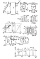
- FIG. 1 shows a generalized basic diagram of a solar energy system.
- This solar energy system comprises a solar energy collector 1 constructed in the form of at least one collector plate adapted to pass a heat transport fluid and having its inlet 2 connected through a duct 3 with a first outlet 4 of a heat accumulator 5.
- the outlet 6 of the solar energy collector 1 communicates through a duct'7 with a first inlet 8 of the heat accumulator 5.
- the heat accumulator 5 has furthermore a second inlet 9 and a second outlet 10.
- the duct 3, the solar energy collector 1 and the duct 7 together with part of the heat accumulator 5 constitute a heat recovery circuit through which passes a heat transport fluid.
- This heat transport fluid is heated by radiation incident to the collector 1 and then serves for enhancing the heat content of the heat accumulator 5.
- the heat capacity flux i.e. the mass flux x the specific heat of the heat transport fluid through the heat recovery circuit is indicated by the arrows W in Fig. 1.
- the heat accumulator 5 is furthermore included in a consumer circuit, part of which is formed by the second inlet 9 and the second outlet 10 of the heat accumulator 5.
- the heat capacity flux through this consumer circuit is indicated in the drawing by the arrows W d .
- the heat capacity flux W d through the consumer circuit depends upon the heat consumption pattern i.e. on the amount of heated fluid and its temperature as a function of time and that it may highly differ from one solar energy system to another.
- This heat capacity flux W d may be considered to be a datum that, in principle, cannot be influenced. This datum may be used for obtaining a high efficiendy of the energy management of the solar.energy system.
- maximum efficiency is attained by adapting the heat capacity flux W through the heat catchment circuit inter alia to be assessed or foreseeable heat capacity flux W d through the consumer circuit.
- the heat capacity flux on the consumer side may, of course, be varied, since the invention relates to the difference between the heat capacity fluxes at the inlet and the outlet W c and W d respectively.
- FIG 1 shows the simplest diagram of a solar energy system.
- Figs. 2a to 2e illustrate more in detail how the heat coupling between the heat recovery circuit and the consumer circuit can be established.
- FIG. 2a shows a heat accumulator 13 having two connections withthe junction of the ducts 7 and 11 and with the junction of the ducts 3 and 12 respectively.
- the topmost duct of the heat accumulator 13 serves both as a first inlet and as a second outlet.
- the lowermost duct of the accumulator 13 serves both as a first outlet and as a second inlet. Therefore, the said top duct is designated by 8, 10 and the lower ducth by 4, 9.
- the solid arrows near the ducts 8, 10, and 4, 9 denote the case in which heated fluid stored in the heat accumulator 13 leaves the heat accumulator 13 in the direction of the duct 11, whereas the broken arrows indicate the case in which relatively cool medium on the lower side in the heat accumulator 13 flows in the direction of the duct 3 for being further heated by a solar energy collector.
- Fig. 2b shows a variant of the arrangement of Fig. 2a.
- the ducts 7 and 11 and the ducts 3 and 12 are not interconnected, but they individually communicate with the heat accumulator 14.
- Figs. 2a and 2b have obviously in common that there is no separation between the heat recovery circuit and the consumer circuit. If it is desired to use the system for hot tapwater supply, the whole system is fed by water from the water mains. For such a use these systems of Figs. 2a and 2b have the disadvantage that the use of anti-freeze agents is not possible.
- Figs. 2c and 2d show an arrangement in which a singular separation is made between the heat recovery circuit and the consumer circuit.
- the heat accumulator 15 comprises a helically wound tubing 26 serving as a heat exchanger 26 connected between the first inlet 8 and the first outlet 4, said helix being completely surrounded by heat transfer fluid of the consumer circuit.
- a heat exchanger helix 27 forms part of the consumer circuit so that here the heat accumulator 16 is completely filled with heat transport fluid of the heat recovery circuit.
- Fig. 2e shows a further development of the arrangement of Fig. 2d.
- the ducts 7 and 10 are not directly coupled with the first inlet 8 and the first outlet 4 respectively of the heat accumulator 16, since between them is, in addition, arranged a heat exchanger 17.
- This heat exchanger 17 is constructed as follows; between the ducts 3 and 7 is arranged a helical duct 28, around which inner helix is arranged substantially coaxially a hollow outer helix 29, the ends of which are connected with the heat accumulator 16 through a duct 30 with the first inlet 8 and through a duct 31 respectively with the first outlet 4.
- Fig. 3 shows a variant of the heat accumulator of Fig. 2b, that is to say, an accumulator without fluid separation between the two circuits.
- the accumulator 32 of Fig. 3 comprises means for ensuring an excellent stratification.
- the first inlet 8 of the accumulator 32 is placed approximately midway the height of the vessel. With this inlet 8 is connected an extremely thin-walled, flexible, "floating" inlet tube 33, the free end of which opens out in the interior of the heat accumulator 32.
- the heat transfer fluid entering through the duct 7 has a temperature T in .
- the fluid inside the heat accumulator 32 has a thermally inhomogeneous structure and may be thermally stratified as is indicated in the graph on the right-hand side of Fig. 3.
- the graph shows the temperature ) plotted on the abscissa as a function of the height with respect to the lower boundary of the accumulator 32. It is known that the density of each fluid depends upon its temperature. If the floating inlet tube 33, particularly its free end were located in such a part of the heat accumulator that the temperature of the fluid inside the inlet tube 33 is higher than that at the point concerned, an upward force is produced, which decreases according as the temperature difference decreases. According to circumstances the same reasoning applies to the situation in which the end of the inlet tube 33 is at a temperature level above T in .
- Fig. 4 shows a heat accumulator 34 communicating on the one hand with the ducts 7 and 3 and on the other hand with a bipartite consumer circuit.
- One part of the consumer circuit is formed by a duct 24, which may be connected with a water mains, by a water inlet from said water mains towards the interior of the accumulator 34, by a second outlet 21 for said water, by a duct 22 in a heat capacity flux meter constructed in the form of a flow rate meter, said duct 22 being finally connected with hot water taps.
- the heat recovery circuit may also include means for measuring the heat capacity flux.
- the second part of the consumer circuit comprises a duct 25, a third inlet for the heat accumulator 34, a heat exchanger helix 27 (see also Fig. 2d), a third outlet 20 and a duct 23 including a pump 36. Between the ducts 23 and 25 is connected a heating system having a plurality of heating units 37. It is emphasized that the heat-capacity flux through the overall consumer circuit, that is to say, the heat capacity flux through the ducts 22, 24 and the ducts 23, 25 corresponds to the heat capacity flux W d through the consumer circuit indicated in Figs. 1, 2 and 3. Hereinafter it will be described more in detail how the results measured by the flow rate meter are used as data for controlling the solar energy system according to the invention.
- the pump 36 is provided with an energizing unit (not shown) for switching it on or off so that the energizing signal is also indicative of the heat capacity flux though the ducts 23, 25.
- the energizing signal together with the output signal of the flow rate meter 35 may serve to determine the overall heat capacity flux through the complete consumer circuit.
- the use of the energizing signal constitutes essentially the simplest form of the aforesaid assessing means.
- Fig. 5 shows by way of example a strongly simplified, stylized diagram of the potential variation of the heat capacity flux W d through the consumer circuit and of the heat capacity flux W c through the heat recovery circuit for a period of about three days. The time is plotted on the abscissa. One day from 0 to 24 hours corresponds to each interval indicated by vertical, broken lines.
- the heat capacity flux W d through the consumer circuit is usually considered as an input datum. This is not altered by a control-system of the embodiments shown. It should be noted, however, that the control criterion according to the invention is concerned with the relationship between the heat capacity fluxes through the heat recovery circuit and the consumer circuit so that an adaptation of the heat capacity flux on the consumer side also lies within the scope of the invention.
- the first need for heat on the side of the consumer(s) occurs, for example, at seven o'clock in the morning.
- the heat emanating from the heat accumulator is employed for heating a house by means of a central heating system, for washing, a shower bath, the preparation of the breakfast and so on.
- This need for heat is found to be comparatively high at the beginning of the day and afterwards it drops to a comparatively low, more or less stable value.
- the need for heat again increases, for example, because most members of a family are at home or because the outdoor temperature becomes lower. A more or less analogous pattern can be found the second day.
- the overall need for heat that is to say, a magnitude corresponding to the integral of W d that can be Derived from the Figure in the form of the surface bounded by the t-axis and the W d curve appears to be higher at the second day than at the first day.
- the third day shows a variation, for example, due to be absence of the consumers, whilst a central heating system automatically switches on at a given instant.
- the increase in heat consumption towards the evening is referred to above.
- Fig. 5 shows the variation of the heat capacity flux W through the heat recovery circuit.
- W appears to be equal to zero. This is to be attributed to the fact that prior to said instant there apparently was.no or no sufficient solar radiation for producing a temperature increase of the heat transport fluid which may flow through the solar energy collector. If the value of W c during the night were not equal to zero the heat content of the accumulator might and even would most probably decrease, since the solar energy collector gives off heat to the surroundings. This is, of course, undesirable, unless cooling rather than heating is aimed at.
- W c the first two days indicated in Fig.
- the interval a and the instant.t in Fig. 5 show by way of example how the desired adaptation of W c can take place under consideration of past and future.
- the interval a has a duration of 24 hours from an instant t - 24 (wherein t is expressed in hours) to the instant t , i.e. the instant at which a control decision is taken, that is to say, at "the present". Strictly speaking the variation after to at the present is not known so that the graphs of Wd and Ware not completed.
- the expected' mean heat capacity flux W d is employed by the consumer circuit as the input datum in order to determine which heat capacity flux W through the heat recovery circuit has to be adjusted for the closest approximation of said criterion, that is to say, the relationship of the mean heat capacity fluxes.
- This rule implies the expectation that during the twelve hours after the instant t o the heat capacity flux W d through the consumer circuit will not appreciably differ from W d during the corresponding twelve hours of the preceding day.
- Fig. 6 illustrates a diagram of a solar energy system according to the invention.
- This system is basically identical to the system shown in Fig. 1, but means are added for controlling partly automatically and partly by external intervention the heat management of the system on the basis of the aforesaid control criteria.
- the heat capacity flux through the heat recovery circuit is obtained from a pump 37 included in the heat recovery circuit.
- the actuation of this pump depends on an energizing unit 38, which in turn receives control-signals from a memory/arithmetic unit 41.
- the consumer circuit includes a flow rate meter 40 for measuring the heat capacity flux through the consumer circuit.
- the output signals of this flow rate meter are applied to the memory/arithmetic unit 41, which also receives data from a time measuring unit 42.
- This time measuring unit 42 may be synchronized with the electric mains, but it may alternatively be formed by a quartz clock.
- To the unit 41 are furthermore applied data emanating from a read-in unit 43.
- This read-in unit 43 may serve to introduce an encoded weather forecast, an expected consumption pattern or the like.
- Known optical display means for the visual indication of data applied by the read-in unit to the memory or of other relevant data or information available in the control-system and of interest to the consumer are omitted from the Figure.
- the arithmetic unit 39 furthermore receives signals emanating from a photo-electric cell 44 and being a measure for the intensity of the incident radiation so that reaction to the instantaneous intensity of this radiation is also possible.
- the arithmetic unit 39 may also be provided with comparison means to ensure detection of the occurrence of a given minimum intensity. This corresponds, for example, to the variation of W c in Fig. 5 during the third day.
- the output signals of the flow rate meter in themselves do not provide sufficient data for determining the heat capacity flux through the duct 11. These output signals have to be multiplied by a factor corresponding to the specific heat of the heat transport fluid concerned. This multiplication can be simply carried out by amplifying or attenuating the output signals of the flow rate meter by the correct value.
- the arithmetic unit 41 may be adapted to process the signal from the photo-electric cell 44 in a manner such that the heat capacity flux W through the heat recovery circuit is varied proportionally to at least approximately the 0.5 power of the equivalent temperature difference diminished by a predetermined threshold value, below which threshold value the heat capacity flux through the heat recovery circuit is maintained at zero value by not energizing the energizing unit 38.
- Fig. 7 shows a variant of the system of Fig..6.
- the difference between the equivalent temperature and the inlet temperature of the collector is assessed by measuring the temperature difference between the inlet and outlet of the solar energy collector, the heat capacity flux through the solar energy collector forming part of the heat recovery circuit and the ambient temperature.
- the inlet and the outlet of the solar energy collector 1 are provided each with a temperature feeler 45 and 46 respectively, whilst in the free surroundings near the solar energy collect- tor, an outer temperature feeler 47 is disposed.
- the temperature feelers 45 and 46 apply their output signals to a measuring and comparing unit 48.
- the output signal of the unit 48 like the output signal of the outer temperature feeler 47 and that of a flow rate meter 49 included in the consumer circuit is applied to an arithmetic unit 50. It will be apparent to the expert that these three input data are sufficient to determine the aforesaid temperature difference. In this example a measurement of the speed of wind is dispensed with because it is assumed that it represents a secondary effect.
- the output signal of the arithmetic unit is applied to an energizing unit 151, which serves to govern the energization condition of a pump 51 included in the duct 3.
- To the computer unit 50 are applied further data in analogy with the system shown in Fig. 7 wich is symbolically designated by the input connection 52.
- Fig. 8 shows a heat accumulator 53 in which a plurality of temperature feelers 54 are distributed from the lower wall to the top wall of the heat accumulator 53.
- the temperature feelers 54 are all connected separately with a temperature measuring unit 55, which is capable of assessing the temperature distribution in the heat accumulator on the basis of the output signals of the temperature feelers 54.
- a temperature variation with the height can be obtained as is graphically indicated on the right-hand side of the heat accumulator 53. It will be obvious that this graphical representation must have a discrete form. For the sake of clarity it is represented in a continuous form.
- the temperature measuring unit is coupled with an arithmetic unit (not shown) for the supply of signals corresponding to the temperature profile or variations thereof.since the shift of the temperature profile in the heat accumulator 53 constitutes an important datum for the combination of heat supply to the accumulator from the heat recovery circuit and the heat dissipation through the consumer circuit. Therefore, the temperature measuring unit 55 may be provided with comparing means coupled, for example, with the lower and the upper temperature feelers 54 in order to detect the rise or the drop of the temperature above or below a given value respectively. As stated above, such a detection can be responded to by increasing or decreasing the heat capacity flux through the heat recovery circuit.
- Fig. 9 shows a simplified variant of the system of Fig. 8, in which a heat accumulator 56 is provided with a temperature feeler 57 arranged at about one third of its height.
- the output signal of the temperature feeler 57 is applied to a temperature measuring and comprising unit 58.
- the latter compares the output signal of the temperature feeler 57 with a comparison signal corresponding to a given temperature in order to detect the occurrence of a given temperature change. It can thus be assessed whether the heat front referred to above passes by the temperature feeler 57.
- the graph on the right-hand side of the heat accumulator 56 shows a temperature variation in the heat accumulator as a function of the height at three different instants.
- the two solid arrows indicate a shift of the heat front.
- the broken arrows indicate the corresponding change of the temperature detected by the temperature feeler 57.
- Fig. 10a shows with reference to a cross-sectional view of a solar energy collector according to the invention, how the equivalent temperature can be measured.
- the collector 66 comprises a trough 67, which is open on the top side and in which a collector plate 70 provided with flow tubes 69 is arranged on a thermally insulating layer 68.
- a cover plate 71 of glass or a transparent synthetic resin On the open top side the trough 67 is covered by a cover plate 71 of glass or a transparent synthetic resin, the downwardly extending sides of which cover the outer sides of the trough 67.
- An air cavity 72 is formed between the collector plate 70 and the cover plate 71.
- Fig. 10 shows that in this embodiment the collector plate 70 has a part cut away for accommodating a separate plate portion 73 in a thermally insulated manner. At the edges the plate portion 73 is surrounded by a thermally insulating cylinder 74, which together with the plate portion 73 and the bottom of the trough 67, defines a space in which a thermally insulating layer 75 is provided.
- the plate portion 73 is provided with tubes 76, which are not traversed by fluid in contrast to the tubes 69. They are filled with fluid and closed at their ends.
- a temperature feeler 77 for example, a semiconductor element is thermally coupled with the plate portion 73.
- the measuring part of the solar energy collector 66 comprising the elements 74 to 77 is designed for indicating the temperature of the solar energy collector in the case of stagnant fluid. This temperature is the equivalent temperature.
- the output signal of the feeler 77 corresponding to its temperature can be applied, fully in analogy with the configuration of Fig. 6, to a memory/computer unit 41 designed for adjusting the heat capacity flux through the heat recovery circuit also on the basis of the assessed equivalent temperature difference.
- the measuring part may, as an alternative, be designated so that it comprises a plate portion corresponding with the plate portion 73 without tubes or with empty tubes.
- the measuring part also comprises a thermally insulated portion of the cover plate.
- the measuring part may be constructed in the form of a separate collector unit.
- Fig. 10b is a plan view of a cut-out portion of the collector shown in Fig. 10a, in which the measuring part is accommodated.
- the respective components are designated by the same reference numerals as in Fig. 12a.
- the detection of the passage of the heat front as it takes place in the accumulator shown in Fig. 9 with the aid of the temperature feeler 57 may, as an alternative, be carried out by means of a bimetallic element arranged at a corresponding place, whose temperature-dependent flexure may serve for the mechanical control of a valve included in the duct 3 or 8.
- the heat catchment circuit may furthermore be employed a pump provided with means lowering the fluid displacement of the pump with an increasing inlet temperature.
- a very compact and very flexible control unit can be obtained by incorporating a number of the electronic control units described in a computer. This applies in particular to the memory 41, the time measuring unit 42, the arithmetic unit 39, the arithmetic unit 50, the temperature measuring unit 55, the temperature measuring and comparing unit 58 and the arithmetic unit 61.
- An important advantage of a programmable computer is that, if desired, drastic modifications of the desired, complicated control strategy can be simply and rapidly carried out, for example, if they are required due to changes of the solar energy system or of the surroundings.
- the separation between the circuits by the additional heat exchanger may, as an alternative and probably with preference, be carried out on the side of the consumer circuit.
- the collector may, for example, be manufactured at lower cost by omitting the conventional cover plate and/or the spectral selective layer.
- the temperature sensor 57 shown in Fig. 9 may be vertically movable. Thus, with the aid of a single sensor information can be obtained about the temperature distribution in the entire storage vessel as, for example, in the embodiment shown in Fig. 8.
Priority Applications (1)
| Application Number | Priority Date | Filing Date | Title |
|---|---|---|---|
| AT81200197T ATE31803T1 (de) | 1980-02-19 | 1981-02-18 | Verfahren zum regeln des energiehaushalts eines energiesystems und auf diesem verfahren basiertes energiesystem. |
Applications Claiming Priority (2)
| Application Number | Priority Date | Filing Date | Title |
|---|---|---|---|
| NL8001008 | 1980-02-19 | ||
| NL8001008A NL8001008A (nl) | 1980-02-19 | 1980-02-19 | Werkwijze voor het regelen van de energiehuishouding van een zonne-energiesysteem, alsmede een daarop gebaseerd zonne-energiesysteem. |
Publications (2)
| Publication Number | Publication Date |
|---|---|
| EP0034396A1 true EP0034396A1 (fr) | 1981-08-26 |
| EP0034396B1 EP0034396B1 (fr) | 1988-01-07 |
Family
ID=19834857
Family Applications (1)
| Application Number | Title | Priority Date | Filing Date |
|---|---|---|---|
| EP81200197A Expired EP0034396B1 (fr) | 1980-02-19 | 1981-02-18 | Procédé pour contrôler la gestion énergétique d'un système énergétique et un système énergétique basé sur cette méthode |
Country Status (10)
| Country | Link |
|---|---|
| US (1) | US4420032A (fr) |
| EP (1) | EP0034396B1 (fr) |
| JP (1) | JPS56137043A (fr) |
| AT (1) | ATE31803T1 (fr) |
| CA (1) | CA1195892A (fr) |
| DE (1) | DE3176593D1 (fr) |
| DK (1) | DK70681A (fr) |
| ES (1) | ES499541A0 (fr) |
| NL (1) | NL8001008A (fr) |
| PT (1) | PT72509B (fr) |
Cited By (4)
| Publication number | Priority date | Publication date | Assignee | Title |
|---|---|---|---|---|
| GB2125533A (en) * | 1982-08-20 | 1984-03-07 | Univ Birmingham | Solar energy collection system |
| EP0455184A1 (fr) * | 1990-04-28 | 1991-11-06 | Rud. Otto Meyer | Procédé de chauffage et/ou refroidissement d'un bâtiment par l'énergie solaire avec utilisation d'une isolation transparente et installation utilisant ce procédé |
| EP1039256A1 (fr) * | 1999-03-23 | 2000-09-27 | Artur Markart | Accumulateur d'eau chaude |
| EP1584882A3 (fr) * | 2004-04-08 | 2008-05-07 | Wolf GmbH | Réservoir d'eau, en particulier accumulateur stratifié |
Families Citing this family (19)
| Publication number | Priority date | Publication date | Assignee | Title |
|---|---|---|---|---|
| JPS60223960A (ja) * | 1984-04-20 | 1985-11-08 | Matsushita Electric Ind Co Ltd | 太陽熱システムの制御方法 |
| JPS6162746A (ja) * | 1984-08-31 | 1986-03-31 | Matsushita Electric Ind Co Ltd | 冷暖房・給湯装置 |
| DE3440275A1 (de) * | 1984-11-03 | 1986-05-15 | Siempelkamp Gießerei GmbH & Co, 4150 Krefeld | Solaranlage |
| US5361215A (en) | 1987-05-27 | 1994-11-01 | Siege Industries, Inc. | Spa control system |
| US6965815B1 (en) | 1987-05-27 | 2005-11-15 | Bilboa Instruments, Inc. | Spa control system |
| DK0880659T3 (da) * | 1996-03-13 | 2000-11-27 | Volker Boehringer | Modulerende solenergi regulator |
| DE19917680A1 (de) * | 1999-04-19 | 2001-03-08 | Winkelmann & Pannhoff Gmbh Sta | Warmwasserspeicher und Verfahren zum Bereitstellen von Warmwasser |
| AT409659B (de) * | 1999-09-24 | 2002-10-25 | Vaillant Gmbh | Schichtenspeicher-anlage |
| EP1561080A1 (fr) * | 2002-11-16 | 2005-08-10 | Karl Heinz Gast | Dispositif de positionnement pour elements de composants de chauffage, procede pour le faire fonctionner et utilisation |
| DE102006045381B3 (de) | 2006-09-26 | 2008-04-10 | Robert Bosch Gmbh | Ermittlungsverfahren eines Beladungszustandes einer Schichtladespeichervorrichtung sowie Schichtladespeichervorrichtung |
| FR2913756A1 (fr) * | 2007-03-14 | 2008-09-19 | Catherine Baldo | Systeme de chauffage solaire independant |
| FR2917488A1 (fr) * | 2007-06-14 | 2008-12-19 | Quezourec Thierry Le | Installation de chauffage central et/ou de production d'eau chaude dont au moins un moyen de captage et/ou de generation de calories est pilote par des moyens d'exploitation de donnees meteorologiques |
| WO2009143933A2 (fr) * | 2008-04-15 | 2009-12-03 | Muscinesi, Auguste | Systeme de chauffage solaire autonome et independant d'une autre source d'energie |
| US8931475B2 (en) * | 2008-07-10 | 2015-01-13 | Brightsource Industries (Israel) Ltd. | Systems and methods for control of a solar power tower using infrared thermography |
| US20100319348A1 (en) * | 2009-05-26 | 2010-12-23 | Worleyparsons Group, Inc. | Waste heat recovery system |
| US8997511B2 (en) * | 2010-09-21 | 2015-04-07 | Denering Berrio | Heating or cooling system featuring a split buffer tank |
| JP6329347B2 (ja) * | 2013-08-07 | 2018-05-23 | 大和ハウス工業株式会社 | 太陽エネルギー利用システム |
| DE102013014503A1 (de) * | 2013-09-02 | 2015-03-05 | Dräger Safety AG & Co. KGaA | Verfahren für die Kühlung eines Fluchtraums in einer Notfallsituation |
| GB2511590B (en) * | 2013-09-06 | 2015-11-11 | Gannet Ltd | An inlet system for a thermal storage vessel |
Citations (1)
| Publication number | Priority date | Publication date | Assignee | Title |
|---|---|---|---|---|
| FR2405443A1 (fr) * | 1977-10-07 | 1979-05-04 | Chatelain Michel | Procede et dispositif de regulation d'une installation de chauffage solaire |
Family Cites Families (6)
| Publication number | Priority date | Publication date | Assignee | Title |
|---|---|---|---|---|
| US3977601A (en) * | 1975-04-14 | 1976-08-31 | Sunlife S.P.A. | System for recovering solar energy and its direct utilization |
| CA994553A (en) * | 1975-05-16 | 1976-08-10 | Canada Square Management Ltd. | Temperature control system |
| US4052000A (en) * | 1976-04-19 | 1977-10-04 | Allen K. Cooper | Solar energy augmented water heating system |
| US4034912A (en) * | 1976-06-07 | 1977-07-12 | Johnson Controls, Inc. | Method and control arrangement for a heating system including solar and fuel-fired heating apparatus |
| DE2637482A1 (de) * | 1976-08-20 | 1978-02-23 | Thyssen Industrie | Stehender, isolierter doppelmantelwaermetauscher |
| US4190199A (en) * | 1978-01-06 | 1980-02-26 | Lennox Industries Inc. | Combination heating system including a conventional furnace, heat pump and solar energy subsystem |
-
1980
- 1980-02-19 NL NL8001008A patent/NL8001008A/nl not_active Application Discontinuation
-
1981
- 1981-02-16 PT PT72509A patent/PT72509B/pt unknown
- 1981-02-18 DE DE8181200197T patent/DE3176593D1/de not_active Expired
- 1981-02-18 ES ES499541A patent/ES499541A0/es active Granted
- 1981-02-18 AT AT81200197T patent/ATE31803T1/de not_active IP Right Cessation
- 1981-02-18 CA CA000371138A patent/CA1195892A/fr not_active Expired
- 1981-02-18 EP EP81200197A patent/EP0034396B1/fr not_active Expired
- 1981-02-18 DK DK70681A patent/DK70681A/da not_active Application Discontinuation
- 1981-02-18 US US06/235,755 patent/US4420032A/en not_active Expired - Fee Related
- 1981-02-19 JP JP2365381A patent/JPS56137043A/ja active Pending
Patent Citations (1)
| Publication number | Priority date | Publication date | Assignee | Title |
|---|---|---|---|---|
| FR2405443A1 (fr) * | 1977-10-07 | 1979-05-04 | Chatelain Michel | Procede et dispositif de regulation d'une installation de chauffage solaire |
Cited By (4)
| Publication number | Priority date | Publication date | Assignee | Title |
|---|---|---|---|---|
| GB2125533A (en) * | 1982-08-20 | 1984-03-07 | Univ Birmingham | Solar energy collection system |
| EP0455184A1 (fr) * | 1990-04-28 | 1991-11-06 | Rud. Otto Meyer | Procédé de chauffage et/ou refroidissement d'un bâtiment par l'énergie solaire avec utilisation d'une isolation transparente et installation utilisant ce procédé |
| EP1039256A1 (fr) * | 1999-03-23 | 2000-09-27 | Artur Markart | Accumulateur d'eau chaude |
| EP1584882A3 (fr) * | 2004-04-08 | 2008-05-07 | Wolf GmbH | Réservoir d'eau, en particulier accumulateur stratifié |
Also Published As
| Publication number | Publication date |
|---|---|
| ES8206817A1 (es) | 1982-08-16 |
| US4420032A (en) | 1983-12-13 |
| NL8001008A (nl) | 1981-09-16 |
| EP0034396B1 (fr) | 1988-01-07 |
| DE3176593D1 (en) | 1988-02-11 |
| ATE31803T1 (de) | 1988-01-15 |
| PT72509A (en) | 1981-03-01 |
| PT72509B (en) | 1982-02-26 |
| ES499541A0 (es) | 1982-08-16 |
| JPS56137043A (en) | 1981-10-26 |
| CA1195892A (fr) | 1985-10-29 |
| DK70681A (da) | 1981-08-20 |
Similar Documents
| Publication | Publication Date | Title |
|---|---|---|
| EP0034396B1 (fr) | Procédé pour contrôler la gestion énergétique d'un système énergétique et un système énergétique basé sur cette méthode | |
| US20180128502A1 (en) | Water Heater Controller or System | |
| US4340030A (en) | Solar heating system | |
| US20110030753A1 (en) | Control of power generation system having thermal energy and thermodynamic engine components | |
| US7971796B2 (en) | Control device for conserving energy of a water heater | |
| Porras-Prieto et al. | Influence of required tank water temperature on the energy performance and water withdrawal potential of a solar water heating system equipped with a heat pipe evacuated tube collector | |
| CN111051804A (zh) | 蓄热装置、蓄热系统及蓄热方法 | |
| Furbo et al. | Smart solar tanks for small solar domestic hot water systems | |
| WO2019143988A1 (fr) | Humidificateur avec détermination automatique d'intervalle de vidange | |
| US4313419A (en) | Solar heating system | |
| US4413614A (en) | Solar heating system | |
| JP2023086633A (ja) | 太陽熱供給システム | |
| Reddy et al. | Solar thermal energy conversion | |
| Fanney | An experimental technique for testing thermosyphon solar hot water systems | |
| Parker | The performance of a solar water heating system in a dwelling in Christchurch, New Zealand | |
| JPS58184444A (ja) | 太陽熱集熱システム | |
| EP0102791A2 (fr) | Système pour assembler de l'énergie solaire | |
| US20240044550A1 (en) | Improvements in heating systems | |
| Ammar et al. | Investigation of optimum parameters for solar domestic hot water system in Alexandria, Egypt | |
| Ghoneim et al. | Design of a solar water heating system for Alexandria, Egypt | |
| HUMIRE | Modelling Latent Heat Thermal Energy Storage with Novel PCM Encapsulation Design | |
| GB2604216A (en) | Improvements in heating systems | |
| Celentano et al. | An experimental study of a “Once-Through” thermosiphon system | |
| JPS5939301A (ja) | 多段濃縮装置の被濃縮液供給量制御システム | |
| Vitali et al. | EXPERIMENTAL HYBRID SOLAR CONCENTRATOR UNIT SYSTEM FOR SANITARY WATER |
Legal Events
| Date | Code | Title | Description |
|---|---|---|---|
| PUAI | Public reference made under article 153(3) epc to a published international application that has entered the european phase |
Free format text: ORIGINAL CODE: 0009012 |
|
| AK | Designated contracting states |
Designated state(s): AT BE CH DE FR GB IT NL SE |
|
| 17P | Request for examination filed |
Effective date: 19820219 |
|
| GRAA | (expected) grant |
Free format text: ORIGINAL CODE: 0009210 |
|
| ITF | It: translation for a ep patent filed |
Owner name: STUDIO INGG. FISCHETTI & WEBER |
|
| AK | Designated contracting states |
Kind code of ref document: B1 Designated state(s): AT BE CH DE FR GB IT LI NL SE |
|
| PG25 | Lapsed in a contracting state [announced via postgrant information from national office to epo] |
Ref country code: NL Effective date: 19880107 Ref country code: FR Free format text: THE PATENT HAS BEEN ANNULLED BY A DECISION OF A NATIONAL AUTHORITY Effective date: 19880107 Ref country code: BE Effective date: 19880107 |
|
| REF | Corresponds to: |
Ref document number: 31803 Country of ref document: AT Date of ref document: 19880115 Kind code of ref document: T |
|
| PG25 | Lapsed in a contracting state [announced via postgrant information from national office to epo] |
Ref country code: SE Effective date: 19880131 |
|
| PG25 | Lapsed in a contracting state [announced via postgrant information from national office to epo] |
Ref country code: AT Effective date: 19880203 |
|
| REF | Corresponds to: |
Ref document number: 3176593 Country of ref document: DE Date of ref document: 19880211 |
|
| PG25 | Lapsed in a contracting state [announced via postgrant information from national office to epo] |
Ref country code: LI Effective date: 19880229 Ref country code: CH Effective date: 19880229 |
|
| EN | Fr: translation not filed | ||
| NLV1 | Nl: lapsed or annulled due to failure to fulfill the requirements of art. 29p and 29m of the patents act | ||
| REG | Reference to a national code |
Ref country code: CH Ref legal event code: PL |
|
| PG25 | Lapsed in a contracting state [announced via postgrant information from national office to epo] |
Ref country code: DE Effective date: 19881101 |
|
| PLBE | No opposition filed within time limit |
Free format text: ORIGINAL CODE: 0009261 |
|
| STAA | Information on the status of an ep patent application or granted ep patent |
Free format text: STATUS: NO OPPOSITION FILED WITHIN TIME LIMIT |
|
| PG25 | Lapsed in a contracting state [announced via postgrant information from national office to epo] |
Ref country code: GB Free format text: LAPSE BECAUSE OF NON-PAYMENT OF DUE FEES Effective date: 19881118 |
|
| GBPC | Gb: european patent ceased through non-payment of renewal fee | ||
| 26N | No opposition filed | ||
| EUG | Se: european patent has lapsed |
Ref document number: 81200197.2 Effective date: 19880105 |