EP0034094B1 - Ensemble de commande d'un réacteur nucléaire - Google Patents
Ensemble de commande d'un réacteur nucléaire Download PDFInfo
- Publication number
- EP0034094B1 EP0034094B1 EP81400175A EP81400175A EP0034094B1 EP 0034094 B1 EP0034094 B1 EP 0034094B1 EP 81400175 A EP81400175 A EP 81400175A EP 81400175 A EP81400175 A EP 81400175A EP 0034094 B1 EP0034094 B1 EP 0034094B1
- Authority
- EP
- European Patent Office
- Prior art keywords
- cover
- vertical
- control assembly
- enclosures
- reactor
- Prior art date
- Legal status (The legal status is an assumption and is not a legal conclusion. Google has not performed a legal analysis and makes no representation as to the accuracy of the status listed.)
- Expired
Links
- 230000007246 mechanism Effects 0.000 claims description 30
- 238000009423 ventilation Methods 0.000 claims description 17
- 239000000463 material Substances 0.000 claims description 7
- 230000003014 reinforcing effect Effects 0.000 claims 1
- 230000002745 absorbent Effects 0.000 description 10
- 239000002250 absorbent Substances 0.000 description 10
- 238000006073 displacement reaction Methods 0.000 description 8
- XLYOFNOQVPJJNP-UHFFFAOYSA-N water Substances O XLYOFNOQVPJJNP-UHFFFAOYSA-N 0.000 description 5
- 230000000712 assembly Effects 0.000 description 4
- 238000000429 assembly Methods 0.000 description 4
- 238000004891 communication Methods 0.000 description 4
- 239000000446 fuel Substances 0.000 description 4
- 238000009413 insulation Methods 0.000 description 4
- 239000011358 absorbing material Substances 0.000 description 3
- 239000011810 insulating material Substances 0.000 description 3
- 238000012423 maintenance Methods 0.000 description 3
- 238000001816 cooling Methods 0.000 description 2
- 230000000694 effects Effects 0.000 description 2
- 238000003780 insertion Methods 0.000 description 2
- 230000037431 insertion Effects 0.000 description 2
- 230000005865 ionizing radiation Effects 0.000 description 2
- 230000003750 conditioning effect Effects 0.000 description 1
- 230000006866 deterioration Effects 0.000 description 1
- 230000005611 electricity Effects 0.000 description 1
- 238000000605 extraction Methods 0.000 description 1
- 239000012530 fluid Substances 0.000 description 1
- 238000004519 manufacturing process Methods 0.000 description 1
- 239000002184 metal Substances 0.000 description 1
- 239000011150 reinforced concrete Substances 0.000 description 1
- 230000002787 reinforcement Effects 0.000 description 1
- 230000035939 shock Effects 0.000 description 1
- 238000013024 troubleshooting Methods 0.000 description 1
- 238000004804 winding Methods 0.000 description 1
Images

Classifications
-
- G—PHYSICS
- G21—NUCLEAR PHYSICS; NUCLEAR ENGINEERING
- G21C—NUCLEAR REACTORS
- G21C7/00—Control of nuclear reaction
- G21C7/06—Control of nuclear reaction by application of neutron-absorbing material, i.e. material with absorption cross-section very much in excess of reflection cross-section
- G21C7/08—Control of nuclear reaction by application of neutron-absorbing material, i.e. material with absorption cross-section very much in excess of reflection cross-section by displacement of solid control elements, e.g. control rods
- G21C7/12—Means for moving control elements to desired position
-
- Y—GENERAL TAGGING OF NEW TECHNOLOGICAL DEVELOPMENTS; GENERAL TAGGING OF CROSS-SECTIONAL TECHNOLOGIES SPANNING OVER SEVERAL SECTIONS OF THE IPC; TECHNICAL SUBJECTS COVERED BY FORMER USPC CROSS-REFERENCE ART COLLECTIONS [XRACs] AND DIGESTS
- Y02—TECHNOLOGIES OR APPLICATIONS FOR MITIGATION OR ADAPTATION AGAINST CLIMATE CHANGE
- Y02E—REDUCTION OF GREENHOUSE GAS [GHG] EMISSIONS, RELATED TO ENERGY GENERATION, TRANSMISSION OR DISTRIBUTION
- Y02E30/00—Energy generation of nuclear origin
- Y02E30/30—Nuclear fission reactors
Definitions
- the invention relates to a control assembly for a nuclear reactor used for the production of electricity or naval propulsion comprising a plurality of sealed enclosures in communication with the interior of the reactor vessel, each containing a movement mechanism for a cluster of neutron absorbing material in the reactor core.
- clusters of highly neutron absorbing material are used which are moved vertically in the reactor core between the fuel elements, so as to regulate the power supplied by the reactor according to the requested power program.
- these clusters of absorbent material also serve to obtain the emergency shutdown of the reactor, when they are dropped all together in the position of maximum insertion into the reactor core.
- displacement mechanisms are used which cooperate with the control rod and which are arranged inside sealed enclosures in communication. with the inside of the reactor vessel where the core is located.
- the displacement mechanisms for example pawls, are driven by a motor device which is generally arranged at the bottom of the sealed enclosures which extend the reactor vessel upwards from the cover of this vessel. Consequently, the height of the sealed enclosures above the ratchet mechanism, cooperating with the control rod, comprising notches also distributed over the length of the rod, must be at least equal to the height of the fuel assemblies.
- Sealed enclosures of very high height must be maintained at their upper part using an anti-seismic device constituted by a plate itself held in position by means of tie rods arranged on the walls of the reactor pool. It is extremely important indeed, to limit the stresses and the deformations in the mechanisms in the event of earthquakes to allow the emergency stop of the reactor by fall of the clusters of absorbent material in the case where the reactor undergoes earthquakes.
- This plate holding the upper part of the sealed enclosures also plays the role of anti-missile plate because it is designed to stop the sealed enclosures in the event that the latter are ejected so as to prevent any deterioration of the adjacent equipment.
- control assemblies as described above have drawbacks due to the fact that their significant height above the cover of the tank substantially increases the height of the latter and its bulk and that the presence of the anti-seismic devices fixed on the walls of the reactor pool complicates the opening and closing operations of the tank cover.
- the presence of the anti-seismic plate above the motors and in the upper part of the sealed enclosures is also troublesome when it is necessary to change a faulty engine or a part of the mechanism located in the sealed enclosure, an operation which 'it is necessary to perform in the presence of ionizing radiation.
- the object of the invention is therefore to propose a control assembly for a nuclear reactor comprising a plurality of sealed enclosures, in communication with the interior of the reactor vessel, extending this vessel above its cover, in the vertical direction and each containing a mechanism for moving a cluster of neutron absorbing material in the reactor core, driven by a motor device, this control assembly being of a reduced height above the cover of the tank and allowing effective protection of watertight enclosures and mechanisms in the event of earthquakes, disassembly and reassembly of the tank cover facilitated, good ventilation of the motor devices of the mechanisms without the use of complex ventilation devices, efficient thermal insulation of all the sealed enclosures, as well as easier access to the motors and to the mechanism placed in the sealed enclosure to carry out any maintenance and troubleshooting operations.
- the motor devices are placed at the top of the sealed enclosures, inside vertical ventilation chimneys and the control assembly comprises a device for supporting and isolating the sealed enclosures constituted by a resistant structure.
- a device for supporting and isolating the sealed enclosures constituted by a resistant structure.
- vertical secured to the cover of the tank occupying the entire height of the sealed enclosures to a level below the level of the drive device, a horizontal plate fixed to the upper part of the vertical structure having openings for the passage of the sealed enclosures as well as '' an envelope and a horizontal plate thermally insulating the sealed enclosures from the external environment to a level below the level of the motor device.
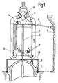
- FIG. 1 we see the tank 1 of a pressurized water nuclear reactor closed at its upper part by a hemispherical cover 2, crossed by a sealed enclosure 3 inside which is disposed a ratchet mechanism 4 allowing the displacement of a control rod of great length, to the lower part of which is fixed an absorbent assembly that the device 4 makes it possible to move inside the reactor.
- control assembly of the reactor comprises a large number of devices each allowing the movement of an absorbent assembly.
- the sealed enclosures 3 are connected at their upper part to an anti-seismic plate of great resistance 6 which is itself held relative to the wall 7 of the reactor pool by a set of anti-seismic tie rods 8.
- a set of lifting rods 9 allows the lifting of the tank cover by a lifting assembly 10 which can be connected to the traveling crane serving the reactor.
- a heat-insulating envelope 13 makes it possible to thermally isolate the cover 2 of the tank from the external environment.
- the height of the sealed enclosure 3 above the mechanisms 4 must be at least equal to the height of the fuel assemblies, which increases the overall size of the reactor vessel or its cover.
- the cover 16 of the tank 15 is crossed by this sealed enclosure 17 extending the tank upwards over a certain height.
- the drive mechanism of the control cluster in its vertical movement inside the core is constituted by a screw and nut device at least partially disposed below the cover 16 of the tank, which makes it possible to reduce the height of the sealed enclosure above the cover of this tank.
- the screw driven in translation is connected to an intermediate rod allowing the attachment of the absorbent cluster to the mechanism.
- a cluster support 19 allows the cluster to be guided when the latter is extracted from the reactor core over a fairly long length.
- this enclosure 20 occupies a height much greater above the cover of the tank than the height occupied by the enclosure 17.
- a vertical resistant structure 23 is fixed on the cover 16 of the tank and extends upwards until '' at a level slightly lower than the level of watertight enclosures such as 17 where the motor devices are located.
- This structure 23 comprises vertical elements 24 of great resistance and horizontal elements 25 constituted by killing a polygonal contour at the lower part and at the upper part of the structure 23 of prismatic shape.
- Stiffening elements 26 ensure the rigidity of the entire structure 23.
- a horizontal plate 27 rests on the horizontal elements 25 at the upper part of the structure and has openings 28 for the passage of the upper parts of the sealed enclosures 17.
- the openings 28 allow passage of the enclosures 17 with a certain clearance so that the enclosures can move freely under the effect of thermal expansion and deformations of the tank cover.
- the reactor vessel and the sealed enclosures contain water under high pressure and at high temperature so that deformations are possible during the operation of the reactor.
- An adapter piece 30 provides the connection between the plate 27 and the sealed enclosure 17 and makes it possible to absorb the shocks between the plate 27 and the enclosure 17 in the event of an earthquake.
- the motors 18 are generally constituted by a flooded rotor disposed inside the enclosure 17 whose axis rotates the nut of the screw-nut mechanism by means of a drive part and by a stator disposed outside the sealed enclosure.
- the motor 18 and the corresponding part of the enclosure are placed inside a chimney 32 which allows, by natural draft, ventilation of the motor 18.
- the set of chimneys such as 32 associated with each of the mechanisms arranged in a sealed enclosure constitutes a removable overall structure 33 fixed by means of a support 34 on the upper part of the vertical structure 23.
- the assembly 33 consisting of chimneys 32 is disposed a little above the horizontal plate 27 ensuring the maintenance of the upper part of the sealed enclosures 17 in the event of an earthquake.
- An enclosure 36 made of insulating material allows thermal insulation of the cover of the tank and of the part of the sealed enclosures 17 placed below the motor 18, with respect to the external environment.
- This large heat-insulating envelope 36 therefore contains all the sealed enclosures 17 passing through the cover 16 of the tank.
- the envelope 36 is closed at its upper part by a horizontal insulating plate 37 placed on the resistant plate 27 and comprising openings corresponding to each of the sealed enclosures containing a mechanism.
- Vertical tie rods 40 allow the lid of the tank to be lifted using a lifting device such as the device 10 shown in FIG. 1.
- the vertical resistant structure 23 and the plate 27 make it possible to constitute an anti-seismic protection device for the reactor control assembly, without the use of tie rods fixed to the walls of the reactor pool.
- the position of the motor above the anti-seismic plate and free access to the upper part of the sealed enclosure allow maintenance of the engine and the mechanism located in the sealed enclosure, without having to dismantle the anti-seismic plate beforehand, which is very advantageous since these works are carried out in the presence of ionizing radiation.
- the main advantages of the device according to the invention are to reduce the height above the tank cover, the control assembly, to avoid the use of anti-seismic tie rods fixed on the walls of the reactor, to allow easy access to the engine and to the mechanism located in the sealed enclosure, to allow natural cooling of the engines in ventilation chimneys, to provide effective thermal insulation of the sealed enclosures containing the mechanisms and to allow faster and easier handling of the tank cover.
- control assembly can be used not only in the case of a pressurized water nuclear reactor with a control moving absorbent clusters using a screw-nut mechanism but also in the case of any other nuclear reactor where the control is carried out by vertical displacement of clusters of absorbent material in the core of the reactor and / or the mechanisms of displacement of the clusters of absorbent material are arranged in sealed enclosures in communication with the interior of the reactor vessel.
Landscapes
- Physics & Mathematics (AREA)
- Engineering & Computer Science (AREA)
- Chemical & Material Sciences (AREA)
- Chemical Kinetics & Catalysis (AREA)
- Plasma & Fusion (AREA)
- General Engineering & Computer Science (AREA)
- High Energy & Nuclear Physics (AREA)
- Structure Of Emergency Protection For Nuclear Reactors (AREA)
- Monitoring And Testing Of Nuclear Reactors (AREA)
- Motor Or Generator Frames (AREA)
Applications Claiming Priority (2)
| Application Number | Priority Date | Filing Date | Title |
|---|---|---|---|
| FR8002861 | 1980-02-08 | ||
| FR8002861A FR2475781A1 (fr) | 1980-02-08 | 1980-02-08 | Ensemble de commande d'un reacteur nucleaire |
Publications (3)
| Publication Number | Publication Date |
|---|---|
| EP0034094A2 EP0034094A2 (fr) | 1981-08-19 |
| EP0034094A3 EP0034094A3 (en) | 1981-09-02 |
| EP0034094B1 true EP0034094B1 (fr) | 1983-06-22 |
Family
ID=9238400
Family Applications (1)
| Application Number | Title | Priority Date | Filing Date |
|---|---|---|---|
| EP81400175A Expired EP0034094B1 (fr) | 1980-02-08 | 1981-02-04 | Ensemble de commande d'un réacteur nucléaire |
Country Status (9)
| Country | Link |
|---|---|
| US (1) | US4708843A (enExample) |
| EP (1) | EP0034094B1 (enExample) |
| JP (1) | JPS56122994A (enExample) |
| BR (1) | BR8100671A (enExample) |
| CA (1) | CA1162334A (enExample) |
| DE (1) | DE3160446D1 (enExample) |
| ES (1) | ES8602288A1 (enExample) |
| FR (1) | FR2475781A1 (enExample) |
| ZA (1) | ZA81574B (enExample) |
Families Citing this family (15)
| Publication number | Priority date | Publication date | Assignee | Title |
|---|---|---|---|---|
| US4797247A (en) * | 1983-07-05 | 1989-01-10 | Westinghouse Electric Corp. | Thermal insulation of nuclear reactor |
| US4574070A (en) * | 1983-07-05 | 1986-03-04 | Westinghouse Electric Corp. | Thermal insulation of nuclear reactor |
| US4678623A (en) * | 1984-02-03 | 1987-07-07 | Westinghouse Electric Corp. | Modular head assembly and method of retrofitting existing nuclear reactor facilities |
| US4828789A (en) * | 1984-02-03 | 1989-05-09 | Westinghouse Electric Corp. | Reactor vessel head permanent shield |
| US4666657A (en) * | 1984-06-22 | 1987-05-19 | Westinghouse Electric Corp. | Remotely adjustable intermediate seismic support |
| US4654188A (en) * | 1985-01-11 | 1987-03-31 | Westinghouse Electric Corp. | Pivotably mounted reactor shroud shield and shielding method |
| US4699752A (en) * | 1985-09-13 | 1987-10-13 | Brahm Leroy D | Shielding device |
| US4830814A (en) * | 1987-06-29 | 1989-05-16 | Westinghouse Electric Corp. | Integrated head package for a nuclear reactor |
| US5084233A (en) * | 1989-02-27 | 1992-01-28 | Combustion Engineering, Inc. | Reactor head shielding apparatus |
| GB2251974B (en) * | 1991-01-17 | 1995-01-11 | Westinghouse Electric Corp | Apparatus + method for passively cooling control rod drive mechanisms in a nuclear reactor |
| FR2701764B1 (fr) * | 1993-02-17 | 1995-05-24 | Framatome Sa | Enceinte de confinement et de recouvrement d'une paroi et en particulier du couvercle de cuve d'un réacteur nucléaire. |
| US5715288A (en) * | 1996-05-09 | 1998-02-03 | Combustion Engineering, Inc. | Integral head rig, head area cable tray and missile shield for pressurized water reactor |
| US5742652A (en) * | 1996-07-16 | 1998-04-21 | Westinghouse Electric Corporation | Head assembly |
| US20040136488A1 (en) * | 2003-07-22 | 2004-07-15 | Wmg, Inc. | Universal modular container for reactor pressure vessel heads |
| JP2009198400A (ja) * | 2008-02-22 | 2009-09-03 | Mitsubishi Heavy Ind Ltd | 制御棒駆動装置の冷却構造及び方法並びに原子炉 |
Family Cites Families (15)
| Publication number | Priority date | Publication date | Assignee | Title |
|---|---|---|---|---|
| US2863815A (en) * | 1953-07-23 | 1958-12-09 | Moore Richard Valentine | Nuclear reactor |
| GB967404A (enExample) * | 1963-05-31 | 1900-01-01 | ||
| US3766006A (en) * | 1970-07-08 | 1973-10-16 | Westinghouse Electric Corp | Rapidly refuelable nuclear reactor |
| US3752737A (en) * | 1970-07-08 | 1973-08-14 | Westinghouse Electric Corp | Combination of nuclear reactor and missile shield |
| US3853699A (en) * | 1970-07-08 | 1974-12-10 | Westinghouse Electric Corp | Nuclear reactor having control-rod retaining means |
| US3836429A (en) * | 1970-07-08 | 1974-09-17 | Westinghouse Electric Corp | Means for rapidly exposing the core of a nuclear reactor for refueling |
| US3940311A (en) * | 1972-01-21 | 1976-02-24 | Westinghouse Electric Corporation | Nuclear reactor internals construction and failed fuel rod detection system |
| BE794342A (fr) * | 1972-01-21 | 1973-07-19 | Westinghouse Electric Corp | Reacteur nucleaire a mecanismes a barre de commande |
| US3800685A (en) * | 1972-08-29 | 1974-04-02 | Tokyo Gas Co Ltd | I-shape duct |
| DE2306947C2 (de) * | 1973-02-13 | 1974-08-15 | Siempelkamp Giesserei Kg, 4150 Krefeld | Vorgespannter Druckbehälter für Atomkernreaktoren |
| US3977939A (en) * | 1973-10-15 | 1976-08-31 | Westinghouse Electric Corporation | Nuclear reactor internals arrangement |
| US4134789A (en) * | 1974-03-01 | 1979-01-16 | Commissariat A L'energie Atomique | Method for refuelling a nuclear reactor and device for carrying out said method |
| US4227967A (en) * | 1977-06-03 | 1980-10-14 | Electric Power Research Institute, Inc. | Method and apparatus for reducing the power level in a nuclear reactor during temperature transient |
| US4272321A (en) * | 1978-06-01 | 1981-06-09 | Combustion Engineering, Inc. | Nuclear reactor internals and control rod handling device |
| FR2432197A1 (fr) * | 1978-07-27 | 1980-02-22 | Commissariat Energie Atomique | Dispositif de commande d'une barre de controle d'un reacteur nucleaire muni de securites contre l'ejection et le chavirement |
-
1980
- 1980-02-08 FR FR8002861A patent/FR2475781A1/fr active Granted
-
1981
- 1981-01-28 ZA ZA00810574A patent/ZA81574B/xx unknown
- 1981-01-28 US US06/229,227 patent/US4708843A/en not_active Expired - Fee Related
- 1981-02-04 JP JP1555981A patent/JPS56122994A/ja active Granted
- 1981-02-04 CA CA000370026A patent/CA1162334A/fr not_active Expired
- 1981-02-04 DE DE8181400175T patent/DE3160446D1/de not_active Expired
- 1981-02-04 EP EP81400175A patent/EP0034094B1/fr not_active Expired
- 1981-02-05 BR BR8100671A patent/BR8100671A/pt not_active IP Right Cessation
- 1981-02-06 ES ES499175A patent/ES8602288A1/es not_active Expired
Also Published As
| Publication number | Publication date |
|---|---|
| ES499175A0 (es) | 1985-11-01 |
| FR2475781B1 (enExample) | 1982-05-14 |
| JPH0224355B2 (enExample) | 1990-05-29 |
| DE3160446D1 (en) | 1983-07-28 |
| FR2475781A1 (fr) | 1981-08-14 |
| EP0034094A3 (en) | 1981-09-02 |
| JPS56122994A (en) | 1981-09-26 |
| EP0034094A2 (fr) | 1981-08-19 |
| US4708843A (en) | 1987-11-24 |
| ES8602288A1 (es) | 1985-11-01 |
| ZA81574B (en) | 1982-02-24 |
| BR8100671A (pt) | 1981-08-18 |
| CA1162334A (fr) | 1984-02-14 |
Similar Documents
| Publication | Publication Date | Title |
|---|---|---|
| EP0034094B1 (fr) | Ensemble de commande d'un réacteur nucléaire | |
| FR2718880A1 (fr) | Réacteur nucléaire refroidi par un métal liquide. | |
| EP0246969B1 (fr) | Petit réacteur nucléaire à eau pressurisée et à circulation naturelle | |
| EP0388253B1 (fr) | Piscine de manutention et de réserve d'eau de sécurité pour réacteur nucléaire refroidi à l'eau sous pression | |
| FR2763168A1 (fr) | Reacteur nucleaire a eau, dont la cuve contient un dispositif de recuperation du coeur apres sa fusion accidentelle | |
| EP0055643B1 (fr) | Réacteur nucléaire refroidi par un métal liquide contenu dans une cuve obturée par des fermetures supérieures | |
| EP0083545B1 (fr) | Dispositif d'évacuation de secours de la chaleur dissipée par un réacteur nucléaire à neutrons rapides à l'arrêt | |
| EP0018262B1 (fr) | Réacteur nucléaire à neutrons rapides et à cuve interne cylindrique | |
| EP0064920B1 (fr) | Dispositif de production de vapeur et de prélèvement de chaleur dans un réacteur nucléaire à neutrons rapides | |
| EP0258131B1 (fr) | Dispositif de refroidissement de secours d'un réacteur nulcléaire à neutrons rapides | |
| EP0156689B1 (fr) | Réacteur nucléaire à neutrons rapides comprenant une cuve principale et une dalle de fermeture suspendues | |
| EP0178215B1 (fr) | Echangeur de chaleur pour le refroidissement d'un fluide par de l'air | |
| EP0047698B1 (fr) | Réacteur nucléaire à circulation du fluide primaire de refroidissement par convection mixte | |
| EP0048672B1 (fr) | Réacteur nucléaire à échangeurs de chaleur intégrés | |
| JP2016090408A (ja) | 原子炉格納容器 | |
| EP0042323B1 (fr) | Installation de stockage et/ou de transfert d'assemblages de combustible nucléaire | |
| EP0095428B1 (fr) | Dispositif de refroidissement par gaz de la dalle de fermeture de la cuve d'un réacteur nucléaire | |
| EP0092461B1 (fr) | Dalle de fermeture annulaire de la cuve d'un réacteur nucléaire à neutrons rapides | |
| WO2023194255A2 (fr) | Cuve interne pour réacteur nucléaire et réacteur comportant plusieurs cuves internes | |
| EP0090743B1 (fr) | Dispositif de protection contre la chaleur et les radiations pour un échangeur de chaleur intermédiaire plongeant dans une cuve de réacteur nucléaire | |
| EP0144256A1 (fr) | Dispositif de protection thermique d'un composant d'un réacteur nucléaire à neutrons rapides | |
| WO2024133281A1 (fr) | Installation nucléaire comprenant au moins un réacteur nucléaire modulaire (smr) et un puits de cuve délimitant un bassin d'eau dans lequel le bloc réacteur smr est immergé | |
| EP4390972A1 (fr) | Installation comprenant au moins un réacteur nucléaire et une fosse de stockage thermique agencée au moins en partie au-dessus du réacteur et reliée à un réseau de chaleur | |
| FR2542909A1 (fr) | Reacteur nucleaire a neutrons rapides de type integre | |
| WO2001050480A1 (fr) | Installation et procede d'entreposage de produits irradies et notamment d'assemblages de combustible nucleaire irradies |
Legal Events
| Date | Code | Title | Description |
|---|---|---|---|
| PUAI | Public reference made under article 153(3) epc to a published international application that has entered the european phase |
Free format text: ORIGINAL CODE: 0009012 |
|
| PUAL | Search report despatched |
Free format text: ORIGINAL CODE: 0009013 |
|
| AK | Designated contracting states |
Designated state(s): BE CH DE GB IT SE |
|
| AK | Designated contracting states |
Designated state(s): BE CH DE GB IT SE |
|
| 17P | Request for examination filed |
Effective date: 19810922 |
|
| ITF | It: translation for a ep patent filed | ||
| GRAA | (expected) grant |
Free format text: ORIGINAL CODE: 0009210 |
|
| AK | Designated contracting states |
Designated state(s): BE CH DE GB IT LI SE |
|
| REF | Corresponds to: |
Ref document number: 3160446 Country of ref document: DE Date of ref document: 19830728 |
|
| PLBE | No opposition filed within time limit |
Free format text: ORIGINAL CODE: 0009261 |
|
| STAA | Information on the status of an ep patent application or granted ep patent |
Free format text: STATUS: NO OPPOSITION FILED WITHIN TIME LIMIT |
|
| 26N | No opposition filed | ||
| ITTA | It: last paid annual fee | ||
| PGFP | Annual fee paid to national office [announced via postgrant information from national office to epo] |
Ref country code: GB Payment date: 19940128 Year of fee payment: 14 |
|
| PGFP | Annual fee paid to national office [announced via postgrant information from national office to epo] |
Ref country code: CH Payment date: 19940216 Year of fee payment: 14 |
|
| PGFP | Annual fee paid to national office [announced via postgrant information from national office to epo] |
Ref country code: SE Payment date: 19940217 Year of fee payment: 14 |
|
| PGFP | Annual fee paid to national office [announced via postgrant information from national office to epo] |
Ref country code: BE Payment date: 19940223 Year of fee payment: 14 |
|
| PGFP | Annual fee paid to national office [announced via postgrant information from national office to epo] |
Ref country code: DE Payment date: 19940428 Year of fee payment: 14 |
|
| EAL | Se: european patent in force in sweden |
Ref document number: 81400175.6 |
|
| PG25 | Lapsed in a contracting state [announced via postgrant information from national office to epo] |
Ref country code: GB Effective date: 19950204 |
|
| PG25 | Lapsed in a contracting state [announced via postgrant information from national office to epo] |
Ref country code: SE Effective date: 19950205 |
|
| PG25 | Lapsed in a contracting state [announced via postgrant information from national office to epo] |
Ref country code: LI Effective date: 19950228 Ref country code: CH Effective date: 19950228 Ref country code: BE Effective date: 19950228 |
|
| BERE | Be: lapsed |
Owner name: FRAMATOME Effective date: 19950228 |
|
| GBPC | Gb: european patent ceased through non-payment of renewal fee |
Effective date: 19950204 |
|
| PG25 | Lapsed in a contracting state [announced via postgrant information from national office to epo] |
Ref country code: DE Effective date: 19951101 |
|
| EUG | Se: european patent has lapsed |
Ref document number: 81400175.6 |