EP0033705B1 - Vorrichtung zur Kapazitätsmessung für eine Wägevorrichtung - Google Patents
Vorrichtung zur Kapazitätsmessung für eine Wägevorrichtung Download PDFInfo
- Publication number
- EP0033705B1 EP0033705B1 EP81400164A EP81400164A EP0033705B1 EP 0033705 B1 EP0033705 B1 EP 0033705B1 EP 81400164 A EP81400164 A EP 81400164A EP 81400164 A EP81400164 A EP 81400164A EP 0033705 B1 EP0033705 B1 EP 0033705B1
- Authority
- EP
- European Patent Office
- Prior art keywords
- capacitance
- frequency
- counter
- measuring
- signal
- Prior art date
- Legal status (The legal status is an assumption and is not a legal conclusion. Google has not performed a legal analysis and makes no representation as to the accuracy of the status listed.)
- Expired
Links
Images


Classifications
-
- G—PHYSICS
- G01—MEASURING; TESTING
- G01G—WEIGHING
- G01G7/00—Weighing apparatus wherein the balancing is effected by magnetic, electromagnetic, or electrostatic action, or by means not provided for in the preceding groups
- G01G7/06—Weighing apparatus wherein the balancing is effected by magnetic, electromagnetic, or electrostatic action, or by means not provided for in the preceding groups by electrostatic action
Definitions
- the present invention relates to a capacity measurement device, applied to weighing instruments of the capacitive transducer type.
- the value of the load to be measured is transformed into that of a capacity.
- the two capacitance electrodes are brought together, thus defining a maximum capacitance value.
- the electrodes move apart, and the capacity value decreases, down to a minimum value which corresponds to the full scale of the weighing instrument.
- this document proposes to alternately insert two capacitors into a relaxation oscillator, the operating frequency of which is inversely proportional to the value of the switched capacitor.
- the same oscillator therefore works sometimes with the capacity to measure, and sometimes with a standard capacity.
- this device does not exempt from the use of a reference time base (circuit 22), that is to say another oscillator making it possible to define the durations of the respective phases of measurement and calibration of each comparison cycle.
- a reference time base circuit 22
- this device does not exempt from the use of a reference time base (circuit 22), that is to say another oscillator making it possible to define the durations of the respective phases of measurement and calibration of each comparison cycle.
- the accuracy of the final measurement is directly dependent on the accuracy and the stability of the clock frequency of this reference time base.
- FR-A-2 381 295 also describes a device of the aforementioned type, where a capacity-frequency converter provides an oscillation frequency proportional to the weight, with storage of the frequency delivered for a zero load. But the final precision is, in the same way, conditioned by that of the reference time base (circuit 400).
- quartz oscillators make it possible to achieve very stable time bases, little subject to drift over time and under the effect of temperature.
- the cost of these circuits prevents their application to mass market products.
- the invention overcomes this difficulty by proposing a capacity measurement device for a weighing instrument which is of simple design, produced from inexpensive components, while exhibiting excellent immunity to the effects of drift which could influence the stability. and the accuracy of the end result.
- the device of the invention which is of the aforementioned type to which FR-A-2 404 229 belongs, has the elements set out in the characterizing part of claim 1.
- a drift - for example a thermal drift - will affect substantially in the same proportions the two oscillators, and therefore the two frequencies FM and FE which will vary in the same ratio.
- the calculation circuit will systematically eliminate the error which would otherwise have resulted.
- the operation of the first capacity-frequency converter is continuous, while the operation of the second capacity-frequency converter is intermittent with alternation of operating phases, allowing the determination of the digital value P, and inhibition , after determining this digital value P, the start of each operating phase being synchronized in phase with the measurement frequency FM, delivered by the first capacitance-frequency converter.
- each capacity-frequency converter comprises an operational amplifier to which the associated capacity is connected in integrator circuit, followed by a comparator circuit with two outputs, one of which provides the FM output frequency; FE and the other is looped on the inverting input of the operational amplifier.
- the triggering threshold of one of the comparator circuits is adjustable.
- the first capacitance-frequency converter comprises a capacitive means to compensate for its internal delays.
- the first capacitance-frequency converter comprises means for producing a correction signal which modifies the comparison threshold by an amount inversely proportional to the measurement frequency FM, the coefficient being adjustable. It is thus possible to carry out a zero adjustment of the device without modifying its measurement range.
- connection between a frame of the capacitive transducer and the inverting input of the associated operational amplifier is shielded, this shielding is connected to the metal frame adjacent to the transducer, and another operational amplifier is provided. able to cancel the potential difference existing between said connection, on the one hand, and the shielding and the chassis, on the other hand.
- the measurement counter circuit comprises a first decade counter stage, and the logic means are switchable so as to authorize counting only over an integer number of periods of the decade counter, which makes it possible to '' round on command a digit of the numerical value P displayed. We can thus obtain a weighing instrument with "magnifying glass”.
- the measurement counter is at least in part a presettable counter, and a control means is provided for presetting a number N by acting on this counter for a predetermined state of the capacity to be measured , such as the absence of load on the weighing instrument. This automatically performs an automatic reset of the weighing instrument.
- FIG. 1 is illustrated the load receptor of an example of a capacitive transducer weighing instrument.
- a frame 20 On a frame 20 is mounted a deformable one-piece parallelogram, consisting of four uprights 11, 12, 21 and 22, joined by throttles 211, 212, 221 and 222.
- the vertical upright 11 rests directly on the frame 20, while the upright 12 is biased by the load Q placed on the load-carrying plate 10 which is connected to it.
- On the fixed upright 11 is fixed the support 31 of a first electrode 320.
- On an intermediate bending arm 23 mounted between the uprights 11 and 12 On an intermediate bending arm 23 mounted between the uprights 11 and 12 is fixed the support 33 of the second electrode 343, which forms with the first 320 a capacitive transducer .
- the first electrode 320 can be moved to adjust the spacing between the two electrodes to the desired value, which corresponds to the maximum capacity. In the presence of a charge, the two electrodes will move apart, resulting in a decrease in capacity. Thus is defined the variable capacity linked to the load to be measured.
- charge receiver with capacitive transducer illustrated here in FIG. 1 is only an example, and many other types of charge receivers can be used, in particular those described in application FR-A-2 456 310. (published on 05.12.80) or FR-A-2 469 701 (published on 22.05.81), in the name of the plaintiff.
- FR-A-2 456 310 published on 05.12.80
- FR-A-2 469 701 published on 22.05.81
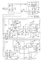
- first capacitance-frequency converter 300 to which is connected the capacitance to be measured defined by its two armatures 320 and 343; there also appears a second capacity-frequency converter 400, to which the standard capacity 420 is connected.
- a switch 421 consisting for example of a field effect transistor, and capable of short-circuiting on controls the standard capacity 420.
- the measurement frequency FM defined by the converter 300 and the standard frequency FE defined by the converter 400 are applied to a calculation circuit 500, which in turn energizes a digital display device 700.
- the mounting finally comprises a power supply circuit 200, as well as an on-off control circuit 100, which reacts by a timed commissioning of the electronic circuits in response to the actuation of an on-off push-button M /AT.
- the supply circuit 200 comprises two batteries 201 and 202, of which the midpoint is connected to the ground of the logic circuits, while the positive pole defines a voltage of 5 V towards the logic circuits of the assembly, namely the components of block 100, of block 500, as well as of block 700. note that this voltage of 5 V is applied permanently, which does not have any consequences in terms of consumption, this logic circuit being advantageously produced in complementary MOS technology.
- the on-off push-button 101 is connected on the one hand to the ground of the logic circuits, and on the other hand by a resistor 102 at the common point to a resistor 104 which goes towards the logic 5 V, and to a capacitor 103 which goes towards the mass.
- the charge of the capacitor 103 which lasts for about one minute, excites a gate 105, which controls the transistor 203 incorporated in the power supply 200, in order to supply the two capacitance-frequency converters 300 and 400.
- the output of the gate 105 is also applied to circuit 500, for the purpose of initial reset.
- V + and V- the two supply voltages thus applied to the capacitance-frequency converters.
- these two voltages are received, and two equal resistors 301 and 302 are connected in series between V + and V-, their midpoint defining the mass of the first capacitance-frequency converter.
- Line V + is also connected by a resistor 303 to a capacitor 305 which goes to the ground in question, while line V- is connected by a resistor 304 to a capacitor 306 which always goes to the same ground.
- a Zener diode 307 Between the extreme terminals of capacitors 305 and 306 is connected a Zener diode 307, which performs voltage regulation.
- This assembly of known type, stabilizes the supply voltage of the converter 300.
- the first converter 300 comprises an operational amplifier 340, the non-inverting input of which is connected by a resistor 341 to ground, that is to say at the common point of the resistors 301 and 302. This same point is connected by a resistor 347, then by a resistor 348 to the inverting input of the operational amplifier 340.
- the armature 320 of the capacity to be measured is also connected to this inverting input, while the other armature 343 is connected to the output of amplifier 340, thus forming an integrating assembly.
- the amplifier 340 is supplied by the voltage across the terminals of the Zener diode 307.
- the output of amplifier 340 is connected by a resistor 355 to the input of a comparator assembly 360, consisting of four NAND gates 361 to 364, also supplied by the voltage across the terminals of diode 307.
- the gate 363 is inactive here.
- the input of comparator 360 is constituted by one of the inputs of door 361, the output of which is connected to an input of doors 362 and 364.
- the other input of doors 362 and 364 is connected in common, as well as at the second entrance to door 361.
- the output of the NAND gate 362 is brought by a parallel network resistor 356 capacitance 357 to the input of the comparator assembly, that is to say the common point between the resistor 355 and one of the inputs of door 361. Resistors 355 and 356 define the threshold from which the comparator will be triggered, both for positive voltages and for negative voltages relative to ground. Finally, the output of gate 362 is brought by a resistor 349 to the common point of resistors 347 and 348, and thereby to the inverting input of amplifier 340.
- this amplifier 340 will therefore see its output voltage rise (FIG. 5A), while the output of gate 362 is at a low level.
- the output exceeds the threshold of the comparator the latter will be inverted, the output of the gate 362 then suddenly passing to the high level, while the amplifier 340 will now integrate with the reverse polarity, which provides a tooth of reciprocating and symmetrical saw ( Figure 5A).
- the output of door 362 will in turn be a square wave, the general shape of which is illustrated in FIG. 5B.
- the operation of the second capacity-frequency converter 400 is substantially the same.
- the midpoint of resistors 401 and 402 is connected by a resistor 441 to the non-inverting input of the operational amplifier 440. Between its inverting input and its output, it receives the standard capacity 420.
- the output of the amplifier 440 is connected by a resistor 455 and part of a potentiometer 458 to a comparator circuit 460 with four NAND doors 461 to 464. Gate 464 is inactive.
- the outlet of door 461 is connected in common to an inlet of door 462 and to an inlet of door 463.
- a signal TR is applied to a resistor 422 which goes to the positive voltage across the terminals of the Zener diode 407, as well as to a capacitor 424 which goes to the common point of the resistors 401 and 402, and also to a resistor 423 which comes to control the gate of an effect transistor field 421 mounted across the standard capacity 420.
- the signal TR is at zero level, that is to say that the signal TR is true, the field effect transistor 421 is made conductive, and the standard capacity 420 remains short-circuited, preventing the operation of the capacity-frequency converter 400.
- the standard capacity 420 being of fixed value, the operation of the capacity-frequency converter 400 does not raise any particular difficulty. It will simply be noted that the potentiometer 458 makes it possible to adjust the value of the standard frequency FE supplied by the output of the gate 463, and thereby to define the numerical value associated with the full measurement scale, in a way that will understand better later.
- the first converter 300 operates with a variable capacity, and therefore at a variable frequency.
- the FM measurement frequency supplied by the output of gate 364 can take large values, values for which the internal delays in this first converter 300 become non-negligible. The Applicant has found various ways to compensate for this delay.
- a capacitor 350 is mounted in parallel on the resistor 348.
- the current injected on the inverting input of the amplifier 340 then has the form illustrated in FIG. 5C, i.e. with a slight peak after each trip of the comparator.
- an additional initial charge is thus given to the capacity to measure 321, 343, and this additional charge compensates for the effect of the delays.
- the output of the amplifier 340 then has the form of FIG. 5D.
- capacitor 350 it is also possible to replace the capacitor 350 with a capacitor 351, illustrated in dashed lines, and connected in parallel to the resistor 355.
- a capacitor 352 also illustrated in dashed line, between the non-inverting input and the output of the operational amplifier 340. The effect is then to bring to the input of the comparator a signal of the form illustrated in FIG. 5D.
- the comparison threshold is then modified by an amount proportional to the FM measurement frequency.
- NAND gate 364 has one of its inputs connected to an input of the gate 361, as well as of the gate 362, and also to the positive voltage across the terminals of the Zener diode 307.
- the other input of door 364 is connected to the output of door 361. There is therefore between this last input of door 364 and its output a voltage which represents a niche of the form illustrated in FIG. 5B.
- this voltage is applied to the extreme terminals of a potentiometer 390, the cursor of which is connected to a resistor 391, which in turn is connected to the common point of a resistor 392 going towards the input of the comparator 360 (common point of the resistor 355 and of the gate 361), and on the other hand to a capacitor 393, which goes towards the positive voltage across the terminals of the Zener diode 307.
- this mass is maintained at the same potential as the armature 320, for example by using an operational amplifier 345 whose inverting input is looped over its output, connected to said ground, while its non-inverting input is connected to the armature 320 of the capacity to measure.
- an operational amplifier 345 whose inverting input is looped over its output, connected to said ground, while its non-inverting input is connected to the armature 320 of the capacity to measure.
- variants can be used, in particular by taking a signal from the comparator 360, since the integration of the slot of FIG. 5B provides a sawtooth signal of the form illustrated in FIG. 5A, therefore exactly a voltage of the same shape as that present on the armature 320 (subject to an inversion).
- the present invention therefore allows satisfactory adjustment of the parameters for transforming the capacity to measure in frequency.
- these adjustments are made so that the maximum value of the frequency of measurement, noted FM max is equal to ten times the value of the standard frequency FE, and that the minimum value of the measurement frequency, noted FM min is equal to half of the maximum value FM max.
- FIG. 4 As well as the corresponding waveforms illustrated in Figure 6.
- the standard frequency FE (FIG. 6B) is applied to a counter 550, of ten bits, the most significant bit of which provides an output signal TR, which changes state after 1024 falling edges of the frequency FE. Using this signal TR, we will find out how many pulses at the measurement frequency FM there are in 1024 pulses at the frequency FE. And it should of course be taken into account that the minimum measurement frequency FM min corresponds to a zero weighed weight.
- the FM measurement frequency is applied through a resistor 501 and a shaping gate 502 on the one hand to a decimal counter 510 with a single decade, which counts on its falling edges, on the other hand to an AND gate 530, on one of its inputs, and on the other hand finally, to an OR gate 532.
- the counter 510 is for example of the "4017" type, sold by NATIONAL SEMICONDUCTOR. Since the FM frequency is produced continuously, the 510 counter rotates continuously. It has an output divided by ten, which provides an FM / 10 signal; the counter 510 being triggered on the falling edges of the FM frequency, this signal FM / 10 will change state on each fifth falling edge, using the restraint at the transition to five which is internal to the counter.
- the form of the FM / 10 signal is illustrated in Figure 6E.
- the counter 510 is followed by a second counter 520, divider by 512, which reacts to the falling edges of the FM / 10 signal.
- An output of the counter 520 provides a signal noted FM / 5120, which will change state after 5120 pulses at the FM measurement frequency.
- a flip-flop 538 moreover supplies a signal VR, which we will admit for the moment that it is at logic value 1.
- This signal VR is applied at the same time as the signal FM / 10 to an OR port 540, the output of which is therefore it also in logic state 1, thus validating the AND gate 530.
- This therefore lets the pulses pass at the FM frequency which it receives, and the rising edges of these pulses are applied to the clock input a flip-flop 531 of type D, the control input D of which receives the signal FM / 5120.
- the signal FM / 5120 goes to logic level 1, and the flip-flop 531 changes state on the rising edge immediately following the FM signal, its output ⁇ delivering then an ACP signal which goes to zero.
- the ACP signal is applied to the OR gate 532, and, going to zero, it will allow the latter to let pass the pulses at the FM measurement frequency, whose falling edges then appear on the output of this gate 532 to be applied to the clock input CK of the memory counter (latch) 570, which is for example the model "74C925" from NATIONAL SEMICONDUCTOR.
- the signal VR assumed at level 1
- an AND gate 541 which receives the signal TR already mentioned, and since the signal VR is at level 1, the signal TR will pass this AND gate 541 to lead to an OR gate 542, the output of which commands the reset of the flip-flop 531, and consequently reset this same flip-flop to zero, which changes its output Q to state 1, and prohibits this causes the pulses at the FM measurement frequency to pass through the OR gate 532 to the counter 570.
- the counting time interval of the counter 570 is therefore defined by the signal ACP in FIG. 61, and the number of pulses counted is illustrated by the signal CKCP in FIG. 6J.
- This figure shows, by way of example, that the counter sees 27 pulses, that is to say 27 falling edges, in the example shown.
- the numerical value obtained, here 27, is then displayed in a manner which will be described later.
- the assembly illustrated in FIG. 4 also comprises a flip-flop 539, of type D, which receives on its clock input the signal FM / 10, active by its rising edges, and on its input D the signal TR already mentioned.
- the Q output of flip-flop 539 therefore provides a signal offset from the signal TR, and this signal is denoted DTR.
- DTR Its shape is illustrated in FIG. 6F, and it can be seen that the DTR signal will rise to level 1 during the first rising edge of the FM / 10 signal, after the TR signal has passed to level 1. And this DTR signal returns at zero level on the first rising edge of the FM / 10 signal, after the TR signal has dropped back to zero level.
- the DTR signal is only true after the counting of the digital value according to the invention has ended.
- This DTR signal is applied to an AND gate 561, which also receives the decoded output 6 of the counter 510 (signal Q6 in FIG. 6G).
- this signal Q6 applied to the input LE of the counter 570, the latter transfers the measured value from its counting section to its memory section.
- the decoded output 8 of the counter 510 is in turn energized (FIG. 6H), and this output is applied at the same time as the signal DTR at the AND gate 562, to reset the counting section of the main counter 570.
- the output of the AND gate 562 is also applied through an OR gate 582 for resetting the counters 520 and 550, thus allowing them to restart.
- the gate 582 receives the signal from the AND gate 105 of FIG. 3, to also ensure the reset to zero of these counters when the output of the AND gate 105 is equal to 1 (capacitor 103 charged). In the end, the signal TR had remained true until this reset. After complementation by the inverter 583, the signal TR was used in the manner already indicated to drive the field effect transistor 421 (FIG. 3), and thus block the oscillator at the standard frequency as long as the signal TR is at the true state.
- the circuit 100 controls the supply of the converters 300 and 400 for approximately one minute, which corresponds to numerous measurement cycles such as that illustrated in FIG. 6. After the first measurement, this one is therefore transferred to the memory part of the counter 570, while a new measurement is made in its counting part.
- the memory part of the counter 570 is designed to operate with a multiplexed display, for which it outputs the indications relating to each decimal digit on outputs a to g, which are therefore applied to a decimal display 701.
- Outputs of decades, denoted 1 , 10, 100 and 1000, are applied to a set of AND gates 702, the outputs of which control, via inverters 703, the various individual displays of the circuit 701.
- a flip-flop 580 receives on its clock input the signal TR, active by its rising edges, and its input D the signal FM / 5120.
- the output Q of this flip-flop 580 will therefore go to level 1 on the rising edge of the signal TR, provided that the oscillator with measurement frequency has exceeded 5120 (this may not happen for the very first measurement after actuation of the button- push-button 101 in FIG. 3).
- the output Q of the flip-flop 580 validates the doors 702, and thus allows the display of the measured value. This display is refreshed each time the counter 570 transfers a new value from its counting section to its memory section.
- the flip-flop 580 In the event that the counting at the measurement frequency has not exceeded 5120 (case already seen), or on the contrary exceeds twice 5120 (exceeding the full scale), it is then the output Q of the flip-flop 580 which is in the true state. This output is applied to an AND gate 581, which also receives an output divided by 512 from the counter 550. Insofar as this counter has exceeded half of its excursion, the AND gate 581 therefore actuates an inverting amplifier 706, which at through a resistor 703 lights up a light-emitting diode 707. The function of diode 707 is then to indicate that the measurement is not in the permitted range, because the measurement frequency is below the minimum frequency, or beyond the maximum value. The flip-flop 580 can be reset to zero by the output of door 105.
- the action on the potentiometer 458 of FIG. 3 makes it possible to play on the FE / N ratio, and by therefore on the value of the full measurement scale.
- the means 390 to 393 described with reference to FIG. 3 allow an adjustment of the minimum value of the measurement frequency FM, by acting on this at the level of the first capacitance-frequency converter 300.
- a particular embodiment of the present invention also allows automatic adjustment of the minimum frequency, using the means illustrated in FIG. 7, which replace the counter 520 in FIG. 4.
- the counter 520 is now split in two 520A and 520B counters, to allow presetting of the maximum counted value.
- the FM / 10 signal is applied directly to the 520B counter; it is applied to the counter 520A through an AND gate 526 which also receives the signal TR, as well as a signal CHO, coming from a circuit 525.
- the counter 520A is reset to zero by the signal coming from the circuit 100 (output of door 105).
- the counter 520B is reset to zero by the signal from the gate 582, as was the counter 520 in FIG. 4.
- the set of parallel outputs of the counters 520A and 520B are applied to a digital comparator 527, which now provides an FM / N signal, which is applied to circuits 531 and 580 of FIG. 4 in place of the output of the counter 520.
- a digital comparator 527 which now provides an FM / N signal, which is applied to circuits 531 and 580 of FIG. 4 in place of the output of the counter 520.
- the operator presses a zero charge push button 528, and this information is transformed into a logic signal in a known manner by a circuit 525, from where I sign CH0 in the true state.
- the measurement which is then made by the circuit according to the invention is introduced by the counter 520A, in which it will remain unchanged after releasing the push button 528.
- the counter 520A will therefore contain a value N, which corresponds to the number of pulses at the measurement frequency for zero load.
- the pulses counted are applied to the counter 520B alone, and when the latter reaches the count N defined by the counter 520A, the output of the digital comparator 527 is energized indicating that the N pulses at the FM frequency which correspond to the zero charge.
- this circuit allows very simple automatic adjustment of the weighing zero.
- the flip-flops 531, 538, 539 and 580 can be the "4013" models from NATIONAL SEMICONDUCTOR, and the counters 520 and 550 can be the "4040" models sold by the same company.
- calculation circuits can be designed, in particular replacing the discrete components with a microprocessor.
Landscapes
- Physics & Mathematics (AREA)
- Electromagnetism (AREA)
- General Physics & Mathematics (AREA)
- Measurement Of Resistance Or Impedance (AREA)
- Investigating Or Analyzing Materials By The Use Of Electric Means (AREA)
- Measuring Frequencies, Analyzing Spectra (AREA)
- Paper (AREA)
- Networks Using Active Elements (AREA)
- Measuring Fluid Pressure (AREA)
- Surgical Instruments (AREA)
- Weight Measurement For Supplying Or Discharging Of Specified Amounts Of Material (AREA)
Claims (9)
Priority Applications (1)
| Application Number | Priority Date | Filing Date | Title |
|---|---|---|---|
| AT81400164T ATE19551T1 (de) | 1980-02-04 | 1981-02-03 | Vorrichtung zur kapazitaetsmessung fuer eine waegevorrichtung. |
Applications Claiming Priority (2)
| Application Number | Priority Date | Filing Date | Title |
|---|---|---|---|
| FR8002376 | 1980-02-04 | ||
| FR8002376A FR2475231A1 (fr) | 1980-02-04 | 1980-02-04 | Dispositif de mesure de capacite, en particulier pour instrument de pesage |
Publications (3)
| Publication Number | Publication Date |
|---|---|
| EP0033705A2 EP0033705A2 (de) | 1981-08-12 |
| EP0033705A3 EP0033705A3 (en) | 1981-08-26 |
| EP0033705B1 true EP0033705B1 (de) | 1986-04-30 |
Family
ID=9238172
Family Applications (1)
| Application Number | Title | Priority Date | Filing Date |
|---|---|---|---|
| EP81400164A Expired EP0033705B1 (de) | 1980-02-04 | 1981-02-03 | Vorrichtung zur Kapazitätsmessung für eine Wägevorrichtung |
Country Status (9)
| Country | Link |
|---|---|
| US (1) | US4366875A (de) |
| EP (1) | EP0033705B1 (de) |
| JP (1) | JPS56122918A (de) |
| AT (1) | ATE19551T1 (de) |
| AU (1) | AU6669481A (de) |
| CA (1) | CA1161074A (de) |
| DE (1) | DE3174498D1 (de) |
| FR (1) | FR2475231A1 (de) |
| ZA (1) | ZA81663B (de) |
Families Citing this family (12)
| Publication number | Priority date | Publication date | Assignee | Title |
|---|---|---|---|---|
| GB2123157B (en) * | 1982-06-22 | 1986-10-15 | Peter Caleb Frederi Wolfendale | Load cells |
| AU545387B2 (en) * | 1982-10-05 | 1985-07-11 | Yamato Scale Company, Limited | Weight and force measuring device |
| JPS59120822A (ja) * | 1982-12-17 | 1984-07-12 | ヘンリ−,ジヨン,ステイ−ル | 組合せ計量装置 |
| FR2541450A1 (fr) * | 1983-02-17 | 1984-08-24 | Testut Aequitas | Instrument de pesage electronique avec masse de reference |
| US4503922A (en) * | 1983-05-26 | 1985-03-12 | Bitronics, Inc. | Electronic bathroom scale apparatus using planar coil sensors |
| EP0302396B1 (de) * | 1987-08-04 | 1992-03-25 | Tanita Corporation | Gewichtssensor vom Kapazitätstyp |
| JPH01165920A (ja) * | 1987-12-23 | 1989-06-29 | Tokyo Electric Co Ltd | 静電容量式電子秤 |
| FR2634554B1 (fr) * | 1988-07-25 | 1991-11-29 | Moulinex Sa | Dispositif de pesage electronique |
| US4970374A (en) * | 1988-09-02 | 1990-11-13 | Matsushita Electric Industrial Co., Ltd. | Automatic heating appliance with weight sensor |
| US5183124A (en) * | 1990-09-07 | 1993-02-02 | John Borchard | Compact self-adjusting weighing system having stable measurement resolution |
| US5672850A (en) * | 1995-06-01 | 1997-09-30 | Liu; Chung-Kuang | Weight sensor with electrostatic capacitance |
| NL2007186C2 (nl) * | 2011-07-28 | 2013-01-29 | Fluid Well Instr B V | Voor hoogfrequente storingen ongevoelige capacitieve meetschakeling. |
Citations (6)
| Publication number | Priority date | Publication date | Assignee | Title |
|---|---|---|---|---|
| FR1593899A (de) * | 1967-12-27 | 1970-06-01 | ||
| FR2043421A5 (de) * | 1969-04-16 | 1971-02-12 | Metrodyne Corp | |
| FR2142732A1 (de) * | 1971-06-24 | 1973-02-02 | Commissariat Energie Atomique | |
| US4115767A (en) * | 1975-11-12 | 1978-09-19 | Kulite Semiconductor Products, Inc. | Apparatus for converting an analog signal into digital form particularly adapted for use in digital counter displays |
| FR2404229A1 (fr) * | 1977-09-23 | 1979-04-20 | Testut Aequitas | Dispositif de mesure de capacite d'un condensateur |
| FR2410280A1 (fr) * | 1977-10-14 | 1979-06-22 | Vaisala Oy | Procede de mesure de faibles capacites |
Family Cites Families (8)
| Publication number | Priority date | Publication date | Assignee | Title |
|---|---|---|---|---|
| US3172493A (en) * | 1961-07-17 | 1965-03-09 | Oskar Glemser | Apparatus for the continuous measurement of variations in the weight of a substance |
| US3314493A (en) * | 1964-11-04 | 1967-04-18 | Kennedy James Patrick | Electrical weigh scale with capacitive transducer |
| BE756157A (fr) * | 1969-09-19 | 1971-02-15 | August Sauter K G | Procede pour elever numeriquement au carre le rapport d'une frequence variable mesuree a une frequence fondamentale constante |
| SU678323A1 (ru) * | 1975-12-18 | 1979-08-05 | Институт Горного Дела Ан Казахской Сср | Способ взвешивани грузов на движущихс объектах |
| US4051721A (en) * | 1976-01-13 | 1977-10-04 | Scope Incorporated | Capacitive force-measuring system |
| US4191268A (en) * | 1977-02-22 | 1980-03-04 | Tanita Corporation | Digital weighing machine |
| JPS5927849B2 (ja) * | 1977-04-12 | 1984-07-09 | 株式会社タニタ製作所 | デジタル表示秤の制御回路 |
| US4273204A (en) * | 1978-05-30 | 1981-06-16 | The Jade Corporation | Capacitive force load cell for weighing scale |
-
1980
- 1980-02-04 FR FR8002376A patent/FR2475231A1/fr active Granted
-
1981
- 1981-01-27 CA CA000369446A patent/CA1161074A/en not_active Expired
- 1981-01-28 US US06/229,157 patent/US4366875A/en not_active Expired - Fee Related
- 1981-01-29 AU AU66694/81A patent/AU6669481A/en not_active Abandoned
- 1981-02-02 ZA ZA00810663A patent/ZA81663B/xx unknown
- 1981-02-03 AT AT81400164T patent/ATE19551T1/de not_active IP Right Cessation
- 1981-02-03 DE DE8181400164T patent/DE3174498D1/de not_active Expired
- 1981-02-03 EP EP81400164A patent/EP0033705B1/de not_active Expired
- 1981-02-04 JP JP1555681A patent/JPS56122918A/ja active Pending
Patent Citations (6)
| Publication number | Priority date | Publication date | Assignee | Title |
|---|---|---|---|---|
| FR1593899A (de) * | 1967-12-27 | 1970-06-01 | ||
| FR2043421A5 (de) * | 1969-04-16 | 1971-02-12 | Metrodyne Corp | |
| FR2142732A1 (de) * | 1971-06-24 | 1973-02-02 | Commissariat Energie Atomique | |
| US4115767A (en) * | 1975-11-12 | 1978-09-19 | Kulite Semiconductor Products, Inc. | Apparatus for converting an analog signal into digital form particularly adapted for use in digital counter displays |
| FR2404229A1 (fr) * | 1977-09-23 | 1979-04-20 | Testut Aequitas | Dispositif de mesure de capacite d'un condensateur |
| FR2410280A1 (fr) * | 1977-10-14 | 1979-06-22 | Vaisala Oy | Procede de mesure de faibles capacites |
Also Published As
| Publication number | Publication date |
|---|---|
| US4366875A (en) | 1983-01-04 |
| CA1161074A (en) | 1984-01-24 |
| DE3174498D1 (en) | 1986-06-05 |
| FR2475231A1 (fr) | 1981-08-07 |
| JPS56122918A (en) | 1981-09-26 |
| EP0033705A2 (de) | 1981-08-12 |
| FR2475231B1 (de) | 1983-08-05 |
| ZA81663B (en) | 1982-03-31 |
| AU6669481A (en) | 1981-08-13 |
| EP0033705A3 (en) | 1981-08-26 |
| ATE19551T1 (de) | 1986-05-15 |
Similar Documents
| Publication | Publication Date | Title |
|---|---|---|
| EP0033705B1 (de) | Vorrichtung zur Kapazitätsmessung für eine Wägevorrichtung | |
| FR2597598A1 (fr) | Dispositif de mesure de forces | |
| EP0083303B1 (de) | Quarzzeitbezugssignalgenerator mit Temperaturkompensation und Uhr mit diesem Signalgenerator | |
| EP0022061B1 (de) | Elektronisches Thermometer | |
| FR2514497A1 (fr) | Dispositif de detection numerique de niveau par fil chaud | |
| EP0007288B1 (de) | Vorrichtung zum Messen der Intensität einer Kraft, transversal angewandt am freien Ende eines einseitig eingeklemmten Biegungsbalkens | |
| FR2594230A1 (fr) | Dispositif pour mesurer une puissance electrique | |
| FR2714461A1 (fr) | Indicateur d'intégrité de marchandises périssables. | |
| FR2554585A1 (fr) | Balance electrique equipee de dispositifs electroniques de detection et de correction | |
| EP0390843A1 (de) | Kodierung mehrerer messwertgrössen an einem reifen. | |
| EP0612982A1 (de) | Messschaltung für Widerstandssensor, insbesondere Krafstoffmesser | |
| EP0554424B1 (de) | Verfahren zur Identifizierung von energieverbrauchenden Lasten in einem zu überwachenden Stromnetz | |
| FR2461258A1 (fr) | Appareil de mesure a indication sonore | |
| EP0165144A1 (de) | Elektronisches Chronometersystem mit hoher Auflösung | |
| FR2554584A1 (fr) | Balance electrique equipee de dispositifs electroniques de detection et d'affichage | |
| CH673198B5 (de) | ||
| CH686469B5 (fr) | Pièce d'horlogerie permettant de faire le point. | |
| FR2584490A1 (fr) | Procede d'affichage de la vitesse et de la distance a bord d'un vehicule automobile. | |
| EP0193421B1 (de) | Kapazitäts-Frequenzumformer, insbesondere für kapazitive Aufnehmer | |
| EP0352587B1 (de) | Elektronisches Wägegerät | |
| EP2757352B1 (de) | Sensorüberwachungssystem und -verwaltungsmethode | |
| FR2795816A1 (fr) | Capteur de niveau | |
| FR2596862A1 (fr) | Detecteur a occultation pour la determination de la concentration d'un gaz, notamment detecteur de fumees | |
| EP0511078B1 (de) | Vorrichtung zur Steuerung eines Kreuzspuleninstrumentes | |
| FR2489509A1 (fr) | Procede et dispositif de mesure electrique de quantites de chaleur |
Legal Events
| Date | Code | Title | Description |
|---|---|---|---|
| PUAI | Public reference made under article 153(3) epc to a published international application that has entered the european phase |
Free format text: ORIGINAL CODE: 0009012 |
|
| PUAL | Search report despatched |
Free format text: ORIGINAL CODE: 0009013 |
|
| PUAL | Search report despatched |
Free format text: ORIGINAL CODE: 0009013 |
|
| AK | Designated contracting states |
Designated state(s): AT BE CH DE GB IT LU NL SE |
|
| AK | Designated contracting states |
Designated state(s): AT BE CH DE GB IT LU NL SE |
|
| 17P | Request for examination filed |
Effective date: 19820128 |
|
| GRAA | (expected) grant |
Free format text: ORIGINAL CODE: 0009210 |
|
| AK | Designated contracting states |
Kind code of ref document: B1 Designated state(s): AT BE CH DE GB IT LI LU NL SE |
|
| REF | Corresponds to: |
Ref document number: 19551 Country of ref document: AT Date of ref document: 19860515 Kind code of ref document: T |
|
| ITF | It: translation for a ep patent filed |
Owner name: JACOBACCI & PERANI S.P.A. |
|
| REF | Corresponds to: |
Ref document number: 3174498 Country of ref document: DE Date of ref document: 19860605 |
|
| R20 | Corrections of a patent specification |
Effective date: 19860616 |
|
| PG25 | Lapsed in a contracting state [announced via postgrant information from national office to epo] |
Ref country code: AT Effective date: 19870203 |
|
| PG25 | Lapsed in a contracting state [announced via postgrant information from national office to epo] |
Ref country code: SE Effective date: 19870204 |
|
| PLBE | No opposition filed within time limit |
Free format text: ORIGINAL CODE: 0009261 |
|
| STAA | Information on the status of an ep patent application or granted ep patent |
Free format text: STATUS: NO OPPOSITION FILED WITHIN TIME LIMIT |
|
| PG25 | Lapsed in a contracting state [announced via postgrant information from national office to epo] |
Ref country code: LU Free format text: LAPSE BECAUSE OF NON-PAYMENT OF DUE FEES Effective date: 19870228 Ref country code: LI Effective date: 19870228 Ref country code: CH Effective date: 19870228 |
|
| 26N | No opposition filed | ||
| BERE | Be: lapsed |
Owner name: TESTUT-AEQUITAS Effective date: 19870228 |
|
| PG25 | Lapsed in a contracting state [announced via postgrant information from national office to epo] |
Ref country code: NL Effective date: 19870901 |
|
| NLV4 | Nl: lapsed or anulled due to non-payment of the annual fee | ||
| REG | Reference to a national code |
Ref country code: CH Ref legal event code: PL |
|
| PG25 | Lapsed in a contracting state [announced via postgrant information from national office to epo] |
Ref country code: DE Effective date: 19871103 |
|
| PG25 | Lapsed in a contracting state [announced via postgrant information from national office to epo] |
Ref country code: GB Free format text: LAPSE BECAUSE OF NON-PAYMENT OF DUE FEES Effective date: 19881118 |
|
| PG25 | Lapsed in a contracting state [announced via postgrant information from national office to epo] |
Ref country code: BE Effective date: 19890228 |
|
| EUG | Se: european patent has lapsed |
Ref document number: 81400164.0 Effective date: 19880215 |