EP0033692A1 - Dispositif pour le prélèvement manuel ou automatique d'un liquide contenu dans un récipient - Google Patents
Dispositif pour le prélèvement manuel ou automatique d'un liquide contenu dans un récipient Download PDFInfo
- Publication number
- EP0033692A1 EP0033692A1 EP81400134A EP81400134A EP0033692A1 EP 0033692 A1 EP0033692 A1 EP 0033692A1 EP 81400134 A EP81400134 A EP 81400134A EP 81400134 A EP81400134 A EP 81400134A EP 0033692 A1 EP0033692 A1 EP 0033692A1
- Authority
- EP
- European Patent Office
- Prior art keywords
- cover
- container
- chamber
- agitator
- flow control
- Prior art date
- Legal status (The legal status is an assumption and is not a legal conclusion. Google has not performed a legal analysis and makes no representation as to the accuracy of the status listed.)
- Withdrawn
Links
Images

Classifications
-
- B—PERFORMING OPERATIONS; TRANSPORTING
- B44—DECORATIVE ARTS
- B44D—PAINTING OR ARTISTIC DRAWING, NOT OTHERWISE PROVIDED FOR; PRESERVING PAINTINGS; SURFACE TREATMENT TO OBTAIN SPECIAL ARTISTIC SURFACE EFFECTS OR FINISHES
- B44D3/00—Accessories or implements for use in connection with painting or artistic drawing, not otherwise provided for; Methods or devices for colour determination, selection, or synthesis, e.g. use of colour tables
- B44D3/003—Methods or devices for colour determination, selection or synthesis, e.g. use of colour tables
-
- B—PERFORMING OPERATIONS; TRANSPORTING
- B44—DECORATIVE ARTS
- B44D—PAINTING OR ARTISTIC DRAWING, NOT OTHERWISE PROVIDED FOR; PRESERVING PAINTINGS; SURFACE TREATMENT TO OBTAIN SPECIAL ARTISTIC SURFACE EFFECTS OR FINISHES
- B44D3/00—Accessories or implements for use in connection with painting or artistic drawing, not otherwise provided for; Methods or devices for colour determination, selection, or synthesis, e.g. use of colour tables
- B44D3/06—Implements for stirring or mixing paints
- B44D3/08—Implements for stirring or mixing paints for liquid or semi-liquid paints
Definitions
- the present invention relates to a device for manual or automatic withdrawal of a liquid contained in a container. It applies in particular, but not exclusively to the preparation of colors, in particular colors intended for the preparation of automobile bodies.
- the boxes containing the basic colors used for the preparation of colors are generally stored in a stirring machine consisting of a piece of furniture comprising shelves which are provided with a mechanical device allowing the '' simultaneous shaking of all colors, once or several times a day, in order to always have a perfectly homogeneous liquid at all times
- Each basic color box is provided with a special cover comprising a manual pouring device, either an articulated valve or a pull tab.
- the operator selects the successive basic shades used in its composition. This composition is usually found on a shade manufacturer's formula and can be viewed by means of a microfilm reader.
- the liquid is then poured, manually by tilting the box, into a container such as a box or a special cup and the measurement is carried out by means of a volumetric dispenser or by means of a balance.
- the invention more particularly aims to suppress the manual pouring operation which requires a certain dexterity, to stop the dose within a gram or a cm 3 and a certain physical strength when it comes take large quantities in a 3 to 5 liter container weighing up to 6 or 7 kg.
- the above-mentioned cover is equipped with an agitator, for example of the type comprising a helical blade secured to a vertical axis rotatably mounted in the cover, so as to create stirring in the vertical direction, and means allowing to animate said blade with a vibratory movement of low vertical amplitude.
- an agitator for example of the type comprising a helical blade secured to a vertical axis rotatably mounted in the cover, so as to create stirring in the vertical direction, and means allowing to animate said blade with a vibratory movement of low vertical amplitude.
- the aforesaid tubular portion is disposed in an area located inside the first container, outside the passage of the helical blade of the agitator. It can for example be coaxial with the drive axis. It is also possible to provide a hollow drive axis playing at the same time the role of this tubular portion.
- the aforesaid flow control device can be manual or automatic. In this case, it is controlled from an apparatus carrying out the volumetric or weight measurement of the liquid poured into the second container.
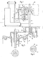
- the apparatus shown in FIG. 1 includes a volumetric metering device 1 on which a metering container 2 is placed.
- a metering stand 3 comprising a base 4 on which is fixed a vertical column 5 along which slides, with the possibility of blocking, a support element 6 comprising two horizontal fork-shaped slides (not shown) on which a special cover 7 is positioned.
- This support element 6 can therefore be adjusted in height as a function of the more or less large dimensions of the pots 8 and of the greater or lesser height of the metering devices 1, so as to obtain jets of minimum length and consequently, greater metering precision.
- This gas intake circuit 9 opens onto the internal face of the cover by means of a valve 10.
- the axis 12 of an agitator which comprises, at its lower end, a helical blade 13.
- the cover 7 comprises on the side opposite to the column 5 and projecting above the metering container 2, a pouring head 14 comprising a nozzle 15 connected to a circuit sampling 16 mounted in the cover 7 and which is connected to a tubular portion 17 intended to immerse in the liquid contained in the container 8 and opening a short distance from the bottom.
- This sampling circuit 16 further comprises, incorporated in the cover, a flow adjustment device 18 actuable by hand for example by means of a control lever 19, or else automatically, by means of a servo device 20 coupled to the volumetric metering device 1.
- control lever 19 can be used to program the quantity to be poured.
- the flow takes place according to the indications of the measuring device, the slowing down of the flow being a function, on the one hand, of the programmed quantity and, on the other hand, of the quantity remaining to be poured.
- the internal air pressure in general of the order of 0.4 bar, allows rapid flow and practically constant whatever the state of filling of the box 8.
- the interior air pressure although low, is much greater than the hydrostatic difference between the full box and the almost empty box.
- the tubular portion 17 of the sampling circuit is coaxial with the drive axis 12 of the agitator. It is fixed on the cover 7 by fitting into a sleeve 22 coaxial with the bearing 23 in which the axis 12 pivots and which defines therewith a coaxial annular chamber 24.
- This chamber 24 communicates through a bore 25 with an intake chamber 26 formed in the cover 7 and which extends in the direction of the pouring head 14. Inside the pouring head 14 is formed a pouring 27 opening to the outside via a nozzle 28 provided with a valve 29 and separated from the intake chamber 26 by a pillar 30 provided with a coaxial bore.
- the inlet 26 and pouring 27 chambers communicate with the outside via two respective holes 32-33 provided on the upper face of the cover 7, on either side of the pillar 30.
- a shutter button 34 On the upper face of the cover is rotatably mounted a shutter button 34 allowing, in the open position, to put the two chambers 26 and 27 in communication, with adjustable flow.
- this shutter button 34 of generally cylindrical appearance, comprises, around a central coaxial pillar 35, an annular recess 36 opening on its underside and interrupted in an area 37 (FIG. 4) sufficiently wide to seal one of the two holes 32-33.
- the mounting of this shutter button 34 on the upper face of the cover 7 is obtained by means of a screw 38 passing through the pillars 30 and 35.
- the seal is then obtained by means of a disc 39 made of a material such as polytetrafluoroethylene or ceramic disposed between the button 36 and the cover 7.
- the sealing pressure can then be ensured by means of a compression spring 40 disposed between the head of the screw 38 and the bottom 41 of the bore formed in the cap 34.
- the width of the annular recess 36 preferably increases from one end to the other (FIG. 4).
- the annular recess 36 comes first to be disposed, by its narrow part, in line with the hole 33.
- the hole 32 is in communication with the wide part of the recess 36.
- the intake 26 and pouring 27 chambers are therefore in communication and the liquid will flow between the two chambers, with a flow rate limited by the width of the recess 36 at the level of the bore 33.
- the more the knob 34 is turned in the direction of opening the more the width of the recess at the level of the hole 33 will be large and the greater the flow will be. This flow rate will become maximum when the width of the recess 36 is at least equal to the diameter of the bore 33.
- the sampling circuit represented in FIG. 5, of principle identical to that previously described, has been more particularly studied to facilitate the return of the liquid in the pot 8, once the control pressure is no longer applied.
- the intake chamber 26 surrounds the bearing 23 of the axis 12 of the agitator. Its lower wall 42 has a shape which is progressively lowered from the orifice 33 to the bearing 23, around which it forms an openwork circular flat 43. From the periphery of this flat 43 leaves a tubular flange 44 coaxial with the bearing and in which the tubular portion 17 is fitted. It therefore appears that the intake chamber 26 communicates with the internal volume of the tubular portion 17 by virtue of the openings 45 in the flat 43.
- the mounting of the obturator plug 34 on the upper face of the cover is carried out in the manner previously described, with the difference that the pillar 30 is replaced by a circular flat portion 46 of the bottom wall 42 of the cover, on which is drilled.
- the cover 7 is equipped with an agitator, the axis 12 of which can be driven on a stirring machine, by means of a fork 47 (FIG. 1).
- the invention is not limited to such a characteristic.
- it could not include an agitator or be equipped with a different type of agitator.
- the agitator's training system could be different.
Landscapes
- Mixers Of The Rotary Stirring Type (AREA)
- Cooling, Air Intake And Gas Exhaust, And Fuel Tank Arrangements In Propulsion Units (AREA)
- Accessories For Mixers (AREA)
Applications Claiming Priority (2)
| Application Number | Priority Date | Filing Date | Title |
|---|---|---|---|
| FR8002275A FR2475009A1 (fr) | 1980-02-01 | 1980-02-01 | Dispositif pour le prelevement manuel ou automatique d'un liquide contenu dans un recipient |
| FR8002275 | 1980-02-01 |
Publications (1)
| Publication Number | Publication Date |
|---|---|
| EP0033692A1 true EP0033692A1 (fr) | 1981-08-12 |
Family
ID=9238126
Family Applications (1)
| Application Number | Title | Priority Date | Filing Date |
|---|---|---|---|
| EP81400134A Withdrawn EP0033692A1 (fr) | 1980-02-01 | 1981-01-29 | Dispositif pour le prélèvement manuel ou automatique d'un liquide contenu dans un récipient |
Country Status (3)
| Country | Link |
|---|---|
| EP (1) | EP0033692A1 (enExample) |
| ES (1) | ES8200839A1 (enExample) |
| FR (1) | FR2475009A1 (enExample) |
Citations (1)
| Publication number | Priority date | Publication date | Assignee | Title |
|---|---|---|---|---|
| US4166705A (en) * | 1978-04-20 | 1979-09-04 | Fronske Handcraft Equipment Corporation | Apparatus for mixing handcraft materials |
-
1980
- 1980-02-01 FR FR8002275A patent/FR2475009A1/fr active Granted
-
1981
- 1981-01-29 EP EP81400134A patent/EP0033692A1/fr not_active Withdrawn
- 1981-01-30 ES ES498992A patent/ES8200839A1/es not_active Expired
Patent Citations (1)
| Publication number | Priority date | Publication date | Assignee | Title |
|---|---|---|---|---|
| US4166705A (en) * | 1978-04-20 | 1979-09-04 | Fronske Handcraft Equipment Corporation | Apparatus for mixing handcraft materials |
Also Published As
| Publication number | Publication date |
|---|---|
| FR2475009B3 (enExample) | 1982-11-26 |
| ES498992A0 (es) | 1981-11-16 |
| ES8200839A1 (es) | 1981-11-16 |
| FR2475009A1 (fr) | 1981-08-07 |
Similar Documents
| Publication | Publication Date | Title |
|---|---|---|
| CA2302855C (fr) | Distributeur portatif pour le conditionnement et la distribution de produits cosmetiques colores | |
| EP0397578B1 (fr) | Doseur-distributeur d'au moins un produit pâteux et/ou liquide | |
| CA2404470C (fr) | Dispositif de conditionnement et de distribution d'un produit liquide | |
| EP0592312B1 (fr) | Doseur, robinet doseur, appareil de dosage en cadence de liquide | |
| EP1307125A1 (fr) | Porte-filtre pour machine a cafe du type "espresso" | |
| FR2568704A1 (fr) | Appareil distributeur distribuant des gobelets contenant des boissons fabriquees instantanement | |
| EP0033692A1 (fr) | Dispositif pour le prélèvement manuel ou automatique d'un liquide contenu dans un récipient | |
| EP0296632A2 (fr) | Dispensateur à poudre | |
| FR2476626A1 (fr) | Appareil de remplissage proportionnel et a un niveau de recipients, tels que des bouteilles | |
| EP2291633B1 (fr) | Appareil de dilution d'un échantillon | |
| EP1011333B1 (fr) | Machine de fabrication et de stockage de levain naturel liquide | |
| EP0606798B1 (fr) | Dispositif doseur pour distribuer du volume de produit et procédé de mélange de ceux-ci | |
| EP0622040B1 (fr) | Machine à café électrique | |
| CA1221202A (fr) | Robinet pour reservoir de chasse d'eau | |
| EP0333586B1 (fr) | Dispositif pour éliminer des impuretés présentes sous forme gazeuse et solide dans un produit liquide contenu dans un réservoir | |
| CH627839A5 (fr) | Doseur de liquide. | |
| FR2625993A3 (fr) | Buse anti-gouttes pour unite doseuse de conditionnement d'un produit a comportement fluide | |
| EP0401456B1 (fr) | Machine pour préparer des infusions de café avec dosage automatique de poudre et d'eau | |
| EP0422499A1 (fr) | Machine de distribution semi-automatique de boissons | |
| EP0400258B1 (fr) | Cafetière avec chaudière et cafetière superposée, et avec siflet de signalisation | |
| FR2555981A1 (fr) | Distributeur de gouttes de verre fondu comportant un dispositif perfectionne pour supporter et faire tourner le tube vertical de melange du distributeur | |
| BE823309A (fr) | Appareil pour la preparation d'infusions de cafe a partir de cafe en poudre | |
| FR2775265A1 (fr) | Dispositif formant vanne d'evacuation d'un produit liquide, tel que du levain naturel liquide, d'une cuve | |
| EP1022249A1 (fr) | Doseur pour dispositif de remplissage volumétrique | |
| FR2467351A1 (fr) | Dispositif de graissage pour appareils a air comprime |
Legal Events
| Date | Code | Title | Description |
|---|---|---|---|
| PUAI | Public reference made under article 153(3) epc to a published international application that has entered the european phase |
Free format text: ORIGINAL CODE: 0009012 |
|
| AK | Designated contracting states |
Designated state(s): AT BE CH DE FR GB IT LU NL SE |
|
| STAA | Information on the status of an ep patent application or granted ep patent |
Free format text: STATUS: THE APPLICATION IS DEEMED TO BE WITHDRAWN |
|
| 18D | Application deemed to be withdrawn |
Effective date: 19820723 |
|
| RIN1 | Information on inventor provided before grant (corrected) |
Inventor name: GODAT, JEAN Inventor name: BOUDIN, DANIEL |