EP0032898B1 - Insulation curtain - Google Patents
Insulation curtain Download PDFInfo
- Publication number
- EP0032898B1 EP0032898B1 EP80900642A EP80900642A EP0032898B1 EP 0032898 B1 EP0032898 B1 EP 0032898B1 EP 80900642 A EP80900642 A EP 80900642A EP 80900642 A EP80900642 A EP 80900642A EP 0032898 B1 EP0032898 B1 EP 0032898B1
- Authority
- EP
- European Patent Office
- Prior art keywords
- curtain
- air
- central portion
- inflatable element
- portions
- Prior art date
- Legal status (The legal status is an assumption and is not a legal conclusion. Google has not performed a legal analysis and makes no representation as to the accuracy of the status listed.)
- Expired
Links
Images


Classifications
-
- E—FIXED CONSTRUCTIONS
- E06—DOORS, WINDOWS, SHUTTERS, OR ROLLER BLINDS IN GENERAL; LADDERS
- E06B—FIXED OR MOVABLE CLOSURES FOR OPENINGS IN BUILDINGS, VEHICLES, FENCES OR LIKE ENCLOSURES IN GENERAL, e.g. DOORS, WINDOWS, BLINDS, GATES
- E06B9/00—Screening or protective devices for wall or similar openings, with or without operating or securing mechanisms; Closures of similar construction
- E06B9/24—Screens or other constructions affording protection against light, especially against sunshine; Similar screens for privacy or appearance; Slat blinds
-
- E—FIXED CONSTRUCTIONS
- E06—DOORS, WINDOWS, SHUTTERS, OR ROLLER BLINDS IN GENERAL; LADDERS
- E06B—FIXED OR MOVABLE CLOSURES FOR OPENINGS IN BUILDINGS, VEHICLES, FENCES OR LIKE ENCLOSURES IN GENERAL, e.g. DOORS, WINDOWS, BLINDS, GATES
- E06B9/00—Screening or protective devices for wall or similar openings, with or without operating or securing mechanisms; Closures of similar construction
- E06B9/02—Shutters, movable grilles, or other safety closing devices, e.g. against burglary
- E06B9/08—Roll-type closures
- E06B9/11—Roller shutters
- E06B9/17—Parts or details of roller shutters, e.g. suspension devices, shutter boxes, wicket doors, ventilation openings
- E06B2009/17069—Insulation
Definitions
- the present invention relates to an insulating curtain, comprising an inflatable element which is intended to cover a surface area when filled with air, and to be kept in a store adjacent said area in a deflated state, there being means adapted for supplying air to the inflatable element, which inflatable element contains at least one central and at least one peripheral airtight portion, the means supplying air being adapted for filling the central portion in conjunction with the element being fed out of the store and filling the peripheral portion when the air supply to the central portion is terminated or almost terminated.
- US-A-3,298,142 relates to a curtain of an extremely complicated nature where the opposing sheets forming the curtain consist of a resilient steel material containing a plurality of airtight tubes in the longitudinal direction of the curtain, said tubes also consisting of a resilient material.
- the whole of this structure can be wound up on a roller, for assisting in this there being a plurality of guide rollers arranged in front of the storage roller and intended to flatten out the resilient outer sheets and the inner air-carrying ducts, thus enabling the curtain to be reeled up on the storage roller.
- US-A-3,231,006 relates to an insulating curtain of the kind disclosed in the preamble of the main claim. In this case, however, the means are lacking which, according to the invention, are necessary for enabling the curtain to be fed out from the store.
- the DE-A-2 026 260 relates to a curtain type of insulating curtain intended for separating and sealing rooms in buildings and it can also be used for insulating windows.
- This curtain is, however, nothing other than an inflatable cushion with regard to its construction, and is intended for placing in a window embrasure, for example.
- None of these known structures could come anywhere near to meeting the requirements for an insulating curtain of the type intended by the invention, and which can be placed immediately adjacent a surface area which is to be insulated, and by the supply of air can be fed out from the store and caused to cover said area, and at a subsequent step be caused to seal either against said area or around it, so that both an insulating and a sealing effect are obtained which is absolutely essential if it is desired to obtain good results from the aspect of conserving energy.
- the sealing and insulating curtain in accordance with the invention is active against heat and cold as well as noise, air pollution and draughts, and can be used as night-time insulation, for example for display windows, greenhouse windows, french windows and ordinary doors and factory doors. It can also be used to prevent evaporation and thereby heat losses, e.g. from swimming pools and other liquid surfaces.
- the object of the present invention is thus to achieve an insulating curtain which can be used for a plurality of different applications when it is a question of preventing heat losses from a surface to the surroundings, while simultaneously constituting an effective seal for dampening noise and preventing the penetration of air pollution.
- the central portion is substantially airtightly compressible between two squeezing or compressing members along at least a portion of its width, the compressed area defining an inflatable part in relation to a substantially airless part, and that air ducts are arranged within a part of the element which is not compressible by the compressing members, to connect the inflating means to the airtight portions, and that feeding the element out from the storage takes place by supplying air to the inflatable part of the central portion.
- the curtain in accordance with the invention illustrated in Figs. 1-3, includes an inflatable element 1, comprising a central portion 9 and two sealing portions 11 on either side thereof.
- the inflatable element is wound up on a storage shaft 3 which in turn is enclosed in a supporting casing or cassette 4.
- the storage shaft 3 is connected to a compressed air source via the air supply pipe 5, and air is introduced at one end of the shaft, from where it is led via a duct 6 to the central portion and also via a duct 7 to the side and sealing portions 11.
- the central portion 9 is taken between two compression rollers 2 pressing against the inflatable element from both sides so that there is formed an area which defines a part to which air is introduced via the duct 6 and an airless portion lying thereunder.
- the compression rollers 2 extend along the whole width of the central portion 9 and the air ducts 6 and 7 must consequently be arranged in one of the sealing portions 11.
- the air is thus supplied through one end of the storage shaft 3 and is distributed to the airtight portions with the aid of a valve means as is apparent from Fig. 14.
- the valve means comprises a closing valve 16 for the duct 6 which takes air to the central portion, and a valve 17 for air supply to both sealing portions.
- the sealing portions communicate with each other via a continuation of the ducts 7 arranged at the bottom edge of the curtain.
- the curtain is suitably produced from a soft and airtight material such as plastic film or a non-woven textile, and the central portion can suitably be built up from parallel segments and in several layers in the reeling direction of the curtain, said segments having certain air communication with segments lying above and below, but are airtightly compartmented off at the sides with respect to adjacent segments.
- the upper part of the curtain is provided with a stiff edge 10 which is formed for being able to guide the curtain when it is being fed in or out from the storage shaft, and for fixing the curtain in a desired position when filling the sealing portions.
- roller adjusting means 14 to set desired pressure between the compression rollers 2, there are roller adjusting means 14, as is apparent from Fig. 9, comprising spacer wedges 28 which act on the wheels 27.
- the spacer wedges are displaced with the aid of a screw 29 which is used to set the desired roller pressure.
- the sealing portions can have an optional configuration depending on how the curtain is placed in relation to the surface area which is to be insulated.
- Fig. 6 an embodiment is illustrated where the sealing portions are caused to expand in a direction substantially transverse of the curtain, the guide elements 13 being intended for stabilizing the side portions.
- Fig. 5 illustrates an alternative embodiment of the curtain with a reinforced upper portion 10a which is apparent in detail from Fig. 11.
- the sealing portions 11 are caused to expand in two directions at right angles to each other in a plane at right angles to the longitudinal direction of the curtain.
- the reinforced edge 10 can suitably be provided with a sensing means, as is apparent from Fig.
- This sensing means is actuated when the central portion has reached its upper end position and the sensing body 37 comes against a surface or stop, whereby the valves 16 and 17 are actuated so that filling the sealing portions 11 is begun while the central portion is being filled.
- the pressure in the central portion as well as in the sealing portions is sensed by a sensor means 33 which is centrally placed, according to Fig. 7, air supply to these portions ceasing when desired pressure has been achieved.
- a sensor means 33 which is centrally placed, according to Fig. 7, air supply to these portions ceasing when desired pressure has been achieved.
- re-reeling of the curtain is done with the aid of a helical spring 19 which is wound round the inner shaft 18 of the storage shaft 3.
- the spring is rigidly fastened by means of an attachment on the shaft 21 and an attachment 20 on the inside of the storage shaft. During the reeling-out movement, when the curtain is reeled from the storage shaft, the spring 19 is charged with energy, and this energy is utilized when the curtain is subsequently reeled back into the store.
- Fig. 1 This introductory stage is illustrated with dashed lines in Fig. 1.
- the sensing body 37 is actuated, according to Fig. 2, by a surface situated above it, the relay contacts illustrated in Fig. 13 being shorted out, which in turn results in that the electromagnetically operated valves 16 and 17 are actuated so that filling the sealing portions is begun while the filling of the central portion with air continues.
- a sensor means in the pressure control valve 33 is actuated, air supply to these portions thus ceasing when the desired pressure has been obtained.
- valves 16 and 17 are once again actuated so that the sealing portions 11 are put into communication with the open air via the duct 5, or with a return duct 34.
- a diaphragm 37a in the sensor means a pair of relay contacts being shorted out to actuate the valve means 16 so that the air in the central portion 9 can flow out freely.
- the inflatable element is reeled up on the storage shaft and the air outflow is accelerated by the compressing force applied by the compression rollers on the central portion, via the torsional'force in the spring 19.
- the inflatable element is in the starting position, i.e. in the position apparent from the bottom portion of Fig. 1.
- Fig. 15 is a perspective view of two alternative embodiments arranged axially symmetric.
- the left hand half has sealing portions 11 going around the central portion 9 and thus intended to expand in a plane at right angles to the reeling-out direction of the curtain.
- Figs. 15 and 16 illustrate the airtight portions filled with air
- Fig. 17 illustrates the curtain during a stage in which only a part of the central portion 9 is inflated, while the sealing portions 11 are substantially deflated.
- the storage means in this case does not comprise a shaft, the inflatable portions being folded on a rigid substructure.
- a rack 41 a driving one of the compression rollers, and is displaceable in a cylinder 38 which is in communication with the compressed air duct 5 and operated by means of the pressure regulating valve 33.
- Both the magnet-controlled valves 16 and 17 are rigidly adapted on the substructure plate in this embodiment, but are controlled in the same way as in the embodiment example first described.
- Fig. 18 illustrates how the sealing portions as well as the central portion can be subdivided into segments to give greater stability to the inflatable element.
- Fig. 20 illustrates in a cross section the curtain according to Figs. 15-17
- Fig. 21 illustrates a cross section through both compression rollers driven by the rack 41 a, the movement of which is translated to the second compression roller by means of the transmission pinion 39b, in the same way as is apparent from Fig. 17.
- Fig. 22 illustrates an alternative drive for the storage shaft, wherein a compressed air cylinder 38 via a transmission system 39-42 translates an axial movement to a rotational movement via the transmission elements 39, 39a which in turn actuate the storage shaft 3 and achieve its rotation.
- the air is directed by means of the pressure regulating valve 33, either into the duct 5 from which air is then taken to the airtight portions, or also to the cylinder 38 for reeling in the curtain.
- Fig. 24 illustrates an alternative arrangement of the compression means wherein one means constitutes the storage shaft, while the other means is a compression roller 2 loaded by a spring 47.
- FIG. 25 illustrates a further embodiment in which two inflatable elements are reeled up on the same storage shaft 3a and where the curtains are intended for reeling out in two directions at right angles to each other.
- the angular direction can naturally be selected optionally.
- Fig. 26 illustrates how two curtains can be caused to seal against each other, e.g. in insulating and sealing large surfaces which cannot be covered by a single curtain, and for this purpose the reinforced edges 10c are provided with valves 44a and outer sealing portions 11 b which resiliently press against each other.
- Figs. 30-39 illustrate curtain arrangements in which the inflatable element is connected to an insulating slab or sheet which by filling and emptying the airtight portions can be caused to cover the surface area which is to be insulated.
- Figs. 30-32 illustrate an embodiment where the central portion 9 and side portions 11 are attached to an insulating sheet 56 and the compression means constitute the sheet 56 and a roller 2 lying against the sheet thereby to achieve the air-sealing action.
- the ducts 6 and 7 can be attached directly to one edge of the sheet, and thus accompany the movement when the sheet is displaced upwards.
- the curtain is returned to the starting position by the action of a) the weight of the sheet 56, b) separate weights 53, and the condition for movement is that it takes place vertically.
- a counterpressure roller 54 arranged in a fixing 55 on the opposite side of the sheet.
- ducts 6 have been arranged leading to the central portion inside the insulating sheet 56, which have made it possible to extend the compression roller 2 to the whole width of the sheet. This is naturally dependent on the duct 6 lying protected in the sheet, so that the side portions 11 c do not need to be utilized for ducts.
- the embodiment according to Fig. 34 relates to a curtain in principle agreeing with the curtain according to Figs. 30-32, but which is intended for horizontal displacement.
- air can thus be taken separately to both sides of the compression means.
- the air In displacement upwards in the Figure the air is taken into the upper part of the central portion, the curtain thus being displaced in this direction.
- the air is introduced into the lower part simultaneously as the upper part is emptied of air.
- Fig. 35 illustrates an embodiment of the invention in which the inner and outer portions are separated and each attached to a separate substructure.
- the inner portion 9c is attached to a substructure 56b suitably in the form of a slab or sheet, which in turn is rigidly attached to a wall portion or the like.
- the compression means in this case constitutes the roller 2a which rolls and presses against the sheet 56, and since air is supplied through the ducts 6 to this part of the central portion, which is either above or below the compressed portion, the insulating sheet 56 is displaced upwards or downwards in the Figure.
- the sealing portion is similarly attached to this sheet, and when the sheet is brought into a completely fed-out position, the filled portion is sealed in accordance with the inventive concept. Through this arrangement the area included in the storage part will also be sealed and insulated. Furthermore, a sealing portion 1 d is inflated when the movement is terminated and the insulating sheet 56 in place.
- Fig. 37 relates to a curtain with its own compressed air source which comprises a compressor 57 driven by an electric motor 58.
- Fig. 38 is a cross section of a compressed air chamber 59 connected to the compressor 57 via the ducts 5.
- Fig. 39 is a cross section through the compressor.
- Fig. 42 is a cross section through the curtain in Fig. 36, and from which it is apparent that the arrangement with the central portion and the sealing portions otherwise agrees with the basic concept of the invention.
- Figs. 40 and 41 illustrate an alternative embodiment of the massive slabs or sheets illustrated in Figs. 32-35.
- the insulating sheet 56 comprises an inner and outer sheet 65 which are separated by air ducts 6a which are filled with air simultaneously as the central portion is supplied with air, whereby an increased sealing action between the compression means is obtained.
- Figs. 43-47 illustrate an embodiment in which the storage part is caused to carry out the inward and outward feed movements while the edge portions of the curtain are attached to a horizontal substructure.
- the inflatable element is reeled up on a storage shaft 3 coacting with a spring-actuated compression roller 2, and the whole arrangement is accommodated in a supporting casing 4.
- Air supply to the central portion as well as to the outer portions takes place through the air ducts 6 and 7 in the same way as in previously described embodiments. Since the storage part 4 in this embodiment has a certain weight, an automatically functioning safety device 78 has been constructed which retains the storage part in a desired position and to which air is supplied via the duct 7 simultaneously as air is supplied to the sealing portions.
- the storage part is provided with wheels 70 and 71 which roll in a groove to one side of the curtain.
- the cassette 74 contains the storage shaft 3 and compression roller 2 and is displaced upwards as air is supplied to the central portion through the duct 6. It will be seen from Fig. 44 that the storage shaft or roller 3 has an outer wheel 3a on which a band 68 can be reeled.
- the cassette 74 is guided during its movement by means of a C-shaped rail 88a in which a runner is displaceable.
- the runner is provided with wheels 70 rolling against one flange of the rail, the band 68 being reeled on or reeled off the wheel 3a on the storage shaft 3 during the movement of the curtain upwards or downwards.
- the band 68 is attached to the upper edge of the rail and is thus completely reeled up on the wheel 3a when the cassette 74 is in its upper position, i.e. when the curtain is completely rolled off from the storage shaft.
- the object of the band is to compel the storage shaft 3 to rotate when the curtain is reeled up on the storage shaft when deflating the inflatable portions, and the cassette moves downward by gravity.
- the rail is provided with a flange 69 intended to guide the reeling on and reeling off of the band from the wheel 3a, and the flange edge has a given slope to plumb, as apparent from Fig. 45 to accommodate the flange to the outside diameter of the wheel and band as the band is reeled on or reeled off it.
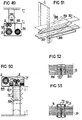
- Fig. 48 illustrates an arrangement in which the sealing portion can be supplemented with further sealing portions intended to be filled with air simultaneously as the sealing portions are filled with air, thereby to reinforce the sealing effect.
- Fig. 49 illustrates another embodiment where the inflatable curtain can be protected from damage, e.g. in display windows, by means of a protective curtain 85 which is similarly reelable on a storage roller and which is attached to the upper edge of the curtain and participates in its movement.
- a protective curtain 85 which is similarly reelable on a storage roller and which is attached to the upper edge of the curtain and participates in its movement.
- Fig. 50 illustrates an arrangement with a raisable and lowerable curtain which can be used as a door and where the storage part is arranged in a roof or the like. To prevent damage to the inflatable element this can be protected by means of sheets 87 made from an impact-proof material which can be con- certinaed together. The sheets are con- certinaed in the storage part on either side of the curtain wall.
- Fig. 51 illustrates a conceivable embodiment of guide elements intended to support the curtain during its upwards and reeling-in movement and to form bearing surfaces to the sealing portions in certain embodiments.
- the reinforced edge 10 will thus take with it the guide strips 88 in its movement upwards, by lifting a transverse rail 89 attached to one end of the strips, while the other end is pivotably mounted in a fixed portion.
- Figs. 52 and 53 illustrate two different embodiments of seals between two parallel driven curtains
- Fig. 52 illustrating a seal where there is a given pressure difference between the central portion 9a and the sealing portion 11 h, resulting in that the central portion will be rigid in comparison with the sealing portions which yieldingly seal against each other and round a guide rail arranged between the curtains.
- Fig. 53 illustrates an arrangement where the sealing effect is achieved with the help of counterpressure rods 13, forming the sealing surfaces against which the sealing portions 11 expand, whereby the sealing portions are pressed against each other.
Landscapes
- Structural Engineering (AREA)
- Engineering & Computer Science (AREA)
- Architecture (AREA)
- Civil Engineering (AREA)
- Curtains And Furnishings For Windows Or Doors (AREA)
- Organic Insulating Materials (AREA)
- Operating, Guiding And Securing Of Roll- Type Closing Members (AREA)
- Inorganic Insulating Materials (AREA)
- Communication Cables (AREA)
- Control Of Vending Devices And Auxiliary Devices For Vending Devices (AREA)
- Internal Circuitry In Semiconductor Integrated Circuit Devices (AREA)
- Magnetic Heads (AREA)
- Gloves (AREA)
- Superconductors And Manufacturing Methods Therefor (AREA)
- Crystals, And After-Treatments Of Crystals (AREA)
Abstract
Description
- The present invention relates to an insulating curtain, comprising an inflatable element which is intended to cover a surface area when filled with air, and to be kept in a store adjacent said area in a deflated state, there being means adapted for supplying air to the inflatable element, which inflatable element contains at least one central and at least one peripheral airtight portion, the means supplying air being adapted for filling the central portion in conjunction with the element being fed out of the store and filling the peripheral portion when the air supply to the central portion is terminated or almost terminated.
- Inflatable elements are previously known, for example through US-A-3,298,142, 3,231,006 and DE-A-2 026 260. US-A-3,298,142 relates to a curtain of an extremely complicated nature where the opposing sheets forming the curtain consist of a resilient steel material containing a plurality of airtight tubes in the longitudinal direction of the curtain, said tubes also consisting of a resilient material. The whole of this structure can be wound up on a roller, for assisting in this there being a plurality of guide rollers arranged in front of the storage roller and intended to flatten out the resilient outer sheets and the inner air-carrying ducts, thus enabling the curtain to be reeled up on the storage roller. Even in a flattened condition the air ducts can, however, supply air from the interior of the storage roller to the area outside the guide rollers, where the resilient material in both outer sheets as well as in the air ducts can assume its natural shape and allow air supply. US-A-3,231,006 relates to an insulating curtain of the kind disclosed in the preamble of the main claim. In this case, however, the means are lacking which, according to the invention, are necessary for enabling the curtain to be fed out from the store.
- The DE-A-2 026 260 relates to a curtain type of insulating curtain intended for separating and sealing rooms in buildings and it can also be used for insulating windows. This curtain is, however, nothing other than an inflatable cushion with regard to its construction, and is intended for placing in a window embrasure, for example.
- None of these known structures could come anywhere near to meeting the requirements for an insulating curtain of the type intended by the invention, and which can be placed immediately adjacent a surface area which is to be insulated, and by the supply of air can be fed out from the store and caused to cover said area, and at a subsequent step be caused to seal either against said area or around it, so that both an insulating and a sealing effect are obtained which is absolutely essential if it is desired to obtain good results from the aspect of conserving energy.
- The sealing and insulating curtain in accordance with the invention is active against heat and cold as well as noise, air pollution and draughts, and can be used as night-time insulation, for example for display windows, greenhouse windows, french windows and ordinary doors and factory doors. It can also be used to prevent evaporation and thereby heat losses, e.g. from swimming pools and other liquid surfaces.
- The object of the present invention is thus to achieve an insulating curtain which can be used for a plurality of different applications when it is a question of preventing heat losses from a surface to the surroundings, while simultaneously constituting an effective seal for dampening noise and preventing the penetration of air pollution.
- This object is essentially realized in accordance with the invention in that the central portion is substantially airtightly compressible between two squeezing or compressing members along at least a portion of its width, the compressed area defining an inflatable part in relation to a substantially airless part, and that air ducts are arranged within a part of the element which is not compressible by the compressing members, to connect the inflating means to the airtight portions, and that feeding the element out from the storage takes place by supplying air to the inflatable part of the central portion.
- A plurality of embodiments of the invention, selected as examples, are described in detail below while referring to the appended drawings on which
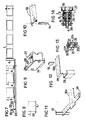
- Fig. 1 is a cross section of an embodiment of the curtain in accordance with the invention,
- Fig. 2 is a longitudinal section in a rolled-out state of the curtain according to Fig. 1,
- Fig. 3 is a plan view of the curtain in Figs. 1 and 2 reeled in with two compression rollers,
- Figs. 4, 5 and 6 illustrate the inflatable element with different configurations of the sealing surfaces,
- Fig. 7 is a principle sketch of the connection of a plurality of curtains to a common pressure source and control means,
- Fig. 8 illustrates a curtain with a separate pressure source,
- Fig. 9 illustrates in perspective a means for regulating the pressure of the compression rollers,
- Figs. 10, 11 and 12 illustrate different embodiments of the upper portion of the inflatable element, and its coaction with control means during the reeling-in and reeling-out movement,
- Fig. 13 is a cross section of a sensing body intended for placing on the upper side of the curtain,
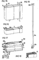
- Fig. 14 is a cross section of a detail of the rotating shaft coupling according to Fig. 2, with magnetically actuated valves,
- Fig. 15 is a perspective view of two different embodiments of the outer portions and of the control means,
- Fig. 16 illustrates a section of the curtain in Fig. 15,
- Fig. 17 illustrates the bottom portion of the curtain in Figs. 15 and 16, where the outer portions have not yet been filled with air, and also an alternative embodiment of the store and driving of the rollers,
- Fig. 18 illustrates an alternative embodiment of the outer and inner portions of the inflatable element,
- Fig. 19 illustrates a compressing and guiding rail for a curtain in accordance with the invention,
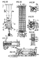
- Fig. 20 is a cross section of a further embodiment of the curtain in accordance with the invention,
- Fig. 21 illustrates two section halves, of which the one on the left is section A-A in Fig. 20, and the one on the right is section B-B according to the same Figure,
- Fig. 22 is a cross section of a curtain according to a still further embodiment of the invention, with a compressed air driven storage shaft,
- Fig. 23 is a longitudinal section of the apparatus in Fig. 22,
- Fig. 24 is a cross section of a shaft coacting directly with a compression means,
- Fig. 25 is a cross section of a shaft on which two curtains are simultaneously rolled up and intended for reeling out in two directions at right angles to each other,
- Fig. 26 illustrates a joint in two curtains in accordance with the invention meeting each other in the same plane,
- Fig. 27 illustrates a reinforced portion with a flap and outside sealing portion for a curtain according to Fig. 26,
- Figs. 28 and 29 illustrate storage units with horizontally and vertically displaceable curtains,
- Fig. 30 is a longitudinal section of a curtain, one end of which consists of a displaceable sheet on which both the outside and the inner portion are attached,
- Fig. 31 is a section in plan of the curtain in Fig. 30,
- Fig. 32 is a cross section of the curtain in Fig. 30,
- Fig. 33 is a perspective view of a counterpressure roller according to Figs. 30-32,
- Fig. 34 is an embodiment of the curtain with an insulating sheet which can suitably be driven horizontally since the displacement of the sheet in both directions takes place by means of separate air supply to opposing parts of the inner portion,
- Fig. 35 illustrates a further embodiment of the curtain in accordance with the invention in which the outer and inner airtight portions are separated and each lies on a separate substructure and the compression roller is attached to the displaceable sheet (section C-C of Fig. 36),
- Fig. 36 illustrates the section A-A in Fig. 35,
- Fig. 37 is a plan view of a curtain with built-in compressed air supply in the storage shaft,
- Fig. 38 is a cross section of a reinforced edge with a compressed air chamber,
- Fig. 39 is a cross section of the storage shaft in Fig. 37 formed as a compressed air source,
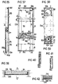
- Fig. 40 is a cross section of an inner portion with compressed ducts,
- Fig. 41 is the curtain in Fig. 40 with air-filled ducts,
- Fig. 42 is a section of the curtain in Fig. 31 with filled sealing portion,
- Fig. 43 is a longitudinal section of a curtain with the storage shaft and compression means arranged in a cassette which is movable upwards and downwards on filling and emptying, respectively, of the inner portion,
- Fig. 44 is a plan view of a detail of the embodiment in Fig. 43 with guide rail and a wheel running along the rail,
- Fig. 45 is a cross section of the curtain in Fig. 43, from which it will be seen that the bottom edge of the curtain is rigidly attached to a substructure and to the compressed air source,
- Fig. 46 illustrates with the same view as in Fig. 44 an alternative embodiment of the guide rail,
- Fig. 47 is a detail of the guide rail in Fig. 45,
- Fig. 48 is a section of a side element with the guide rail and a sealing portion which is filled simultaneously as the sealing portion rolls up on the shaft,
- Fig. 49 is a section of a curtain, the upper edge of which is connected to a separately reelable protective net,
- Fig. 50 is a section of a curtain surrounded on both sides by stiff and foldable protective sheets,
- Fig. 51 is a perspective view of collapsible guiding and sealing rods in different stages of being folded out and driven by the upper edge of the curtain,
- Fig. 52 is a plan view of a sealing joint between two parallel-driven curtains with pressure differentiation between outer and inner portions,
- Fig. 53 similarly illustrates a sealing joint where the sealing effect is obtained by means of opposing pressure rods.
- The curtain in accordance with the invention, illustrated in Figs. 1-3, includes an
inflatable element 1, comprising acentral portion 9 and twosealing portions 11 on either side thereof. According to this embodiment the inflatable element is wound up on astorage shaft 3 which in turn is enclosed in a supporting casing orcassette 4. Thestorage shaft 3 is connected to a compressed air source via theair supply pipe 5, and air is introduced at one end of the shaft, from where it is led via aduct 6 to the central portion and also via aduct 7 to the side and sealingportions 11. Thecentral portion 9 is taken between twocompression rollers 2 pressing against the inflatable element from both sides so that there is formed an area which defines a part to which air is introduced via theduct 6 and an airless portion lying thereunder. Thecompression rollers 2 extend along the whole width of thecentral portion 9 and theair ducts portions 11. The air is thus supplied through one end of thestorage shaft 3 and is distributed to the airtight portions with the aid of a valve means as is apparent from Fig. 14. The valve means comprises a closingvalve 16 for theduct 6 which takes air to the central portion, and avalve 17 for air supply to both sealing portions. The sealing portions communicate with each other via a continuation of theducts 7 arranged at the bottom edge of the curtain. The curtain is suitably produced from a soft and airtight material such as plastic film or a non-woven textile, and the central portion can suitably be built up from parallel segments and in several layers in the reeling direction of the curtain, said segments having certain air communication with segments lying above and below, but are airtightly compartmented off at the sides with respect to adjacent segments. The upper part of the curtain is provided with astiff edge 10 which is formed for being able to guide the curtain when it is being fed in or out from the storage shaft, and for fixing the curtain in a desired position when filling the sealing portions. To set desired pressure between thecompression rollers 2, there are roller adjusting means 14, as is apparent from Fig. 9, comprisingspacer wedges 28 which act on thewheels 27. The spacer wedges are displaced with the aid of ascrew 29 which is used to set the desired roller pressure. The sealing portions can have an optional configuration depending on how the curtain is placed in relation to the surface area which is to be insulated. In Fig. 6 an embodiment is illustrated where the sealing portions are caused to expand in a direction substantially transverse of the curtain, theguide elements 13 being intended for stabilizing the side portions. Fig. 5 illustrates an alternative embodiment of the curtain with a reinforcedupper portion 10a which is apparent in detail from Fig. 11. In this embodiment the sealingportions 11 are caused to expand in two directions at right angles to each other in a plane at right angles to the longitudinal direction of the curtain. The reinforcededge 10 can suitably be provided with a sensing means, as is apparent from Fig. 13, and which is indicated in Figs. 2 and 3. This sensing means is actuated when the central portion has reached its upper end position and thesensing body 37 comes against a surface or stop, whereby thevalves portions 11 is begun while the central portion is being filled. The pressure in the central portion as well as in the sealing portions is sensed by a sensor means 33 which is centrally placed, according to Fig. 7, air supply to these portions ceasing when desired pressure has been achieved. According to the embodiment shown in Fig. 2, re-reeling of the curtain is done with the aid of ahelical spring 19 which is wound round theinner shaft 18 of thestorage shaft 3. The spring is rigidly fastened by means of an attachment on theshaft 21 and anattachment 20 on the inside of the storage shaft. During the reeling-out movement, when the curtain is reeled from the storage shaft, thespring 19 is charged with energy, and this energy is utilized when the curtain is subsequently reeled back into the store. - A complete cycle of reeling-out and reeling-in will now be described in conjunction with the Figures described above. The cycle is thus begun by manual or automatic actuation of the
pressure regulating valve 33 which puts the compressed air chamber 32 in communication with theduct 5, to which theinflatable elements 1 are connected. Air is supplied through the rotatingcoupling 15 and into the valve means where thevalve element 16 for theduct 6 is actuated such that air is let into this duct which is reeled up together with the sealing portion on the outer part of the storage shaft. Theduct 6 opens out into the upper part of thecentral portion 9, and as is apparent from the cross section in Fig. 1, the supply of air to this portion signifies that it is caused to expand, whereby the curtain begins to raise itself simultaneously as it is rolled off thestorage shaft 3. This introductory stage is illustrated with dashed lines in Fig. 1. When the inflatable element has attained its completely reeled-out position, thesensing body 37 is actuated, according to Fig. 2, by a surface situated above it, the relay contacts illustrated in Fig. 13 being shorted out, which in turn results in that the electromagnetically operatedvalves pressure control valve 33 is actuated, air supply to these portions thus ceasing when the desired pressure has been obtained. When the curtain is to be reeled back onto the roller, thevalves portions 11 are put into communication with the open air via theduct 5, or with areturn duct 34. When the pressure in these portions has dropped sufficiently, this is sensed by adiaphragm 37a in the sensor means, a pair of relay contacts being shorted out to actuate the valve means 16 so that the air in thecentral portion 9 can flow out freely. As the air flows out of the central portion the inflatable element is reeled up on the storage shaft and the air outflow is accelerated by the compressing force applied by the compression rollers on the central portion, via the torsional'force in thespring 19. When all the air is emptied, the inflatable element is in the starting position, i.e. in the position apparent from the bottom portion of Fig. 1. - The embodiment described above operates in accordance with the basic principle for a curtain in accordance with the present invention and can be applied to a plurality of different variants illustrated on the other drawing Figures. The distinguishing features set forth in the main claim are, however, common to all of these embodiments.
- Fig. 15 is a perspective view of two alternative embodiments arranged axially symmetric. In the section in Fig. 16 it is apparent, inter alia, that the left hand half has sealing
portions 11 going around thecentral portion 9 and thus intended to expand in a plane at right angles to the reeling-out direction of the curtain. While Figs. 15 and 16 illustrate the airtight portions filled with air Fig. 17 illustrates the curtain during a stage in which only a part of thecentral portion 9 is inflated, while the sealingportions 11 are substantially deflated. The storage means in this case does not comprise a shaft, the inflatable portions being folded on a rigid substructure. The return movement is carried out in this case with the help of arack 41 a driving one of the compression rollers, and is displaceable in acylinder 38 which is in communication with thecompressed air duct 5 and operated by means of thepressure regulating valve 33. Both the magnet-controlledvalves rack 41 a, the movement of which is translated to the second compression roller by means of thetransmission pinion 39b, in the same way as is apparent from Fig. 17. - Fig. 22 illustrates an alternative drive for the storage shaft, wherein a
compressed air cylinder 38 via a transmission system 39-42 translates an axial movement to a rotational movement via thetransmission elements 39, 39a which in turn actuate thestorage shaft 3 and achieve its rotation. Depending on whether the inflatable element is to be reeled in or reeled out, the air is directed by means of thepressure regulating valve 33, either into theduct 5 from which air is then taken to the airtight portions, or also to thecylinder 38 for reeling in the curtain. Fig. 24 illustrates an alternative arrangement of the compression means wherein one means constitutes the storage shaft, while the other means is acompression roller 2 loaded by aspring 47. Fig. 25 illustrates a further embodiment in which two inflatable elements are reeled up on thesame storage shaft 3a and where the curtains are intended for reeling out in two directions at right angles to each other. The angular direction can naturally be selected optionally. Fig. 26 illustrates how two curtains can be caused to seal against each other, e.g. in insulating and sealing large surfaces which cannot be covered by a single curtain, and for this purpose the reinforcededges 10c are provided with valves 44a andouter sealing portions 11 b which resiliently press against each other. - Figs. 30-39 illustrate curtain arrangements in which the inflatable element is connected to an insulating slab or sheet which by filling and emptying the airtight portions can be caused to cover the surface area which is to be insulated. Figs. 30-32 illustrate an embodiment where the
central portion 9 andside portions 11 are attached to an insulatingsheet 56 and the compression means constitute thesheet 56 and aroller 2 lying against the sheet thereby to achieve the air-sealing action. When air is let in via theduct 6 to the central portion, the sheet as well as the inflatable element are displaced upwards, as is indicated in Fig. 32. In this embodiment, theducts sheet 56, b)separate weights 53, and the condition for movement is that it takes place vertically. To achieve the desired compression action between thesheet 56 and theroller 2, there is acounterpressure roller 54 arranged in a fixing 55 on the opposite side of the sheet. In thisembodiment ducts 6 have been arranged leading to the central portion inside the insulatingsheet 56, which have made it possible to extend thecompression roller 2 to the whole width of the sheet. This is naturally dependent on theduct 6 lying protected in the sheet, so that theside portions 11 c do not need to be utilized for ducts. - The embodiment according to Fig. 34 relates to a curtain in principle agreeing with the curtain according to Figs. 30-32, but which is intended for horizontal displacement. According to this embodiment air can thus be taken separately to both sides of the compression means. In displacement upwards in the Figure the air is taken into the upper part of the central portion, the curtain thus being displaced in this direction. For downward displacement in the Figure, the air is introduced into the lower part simultaneously as the upper part is emptied of air.
- Fig. 35 illustrates an embodiment of the invention in which the inner and outer portions are separated and each attached to a separate substructure. The
inner portion 9c is attached to asubstructure 56b suitably in the form of a slab or sheet, which in turn is rigidly attached to a wall portion or the like. The compression means in this case constitutes theroller 2a which rolls and presses against thesheet 56, and since air is supplied through theducts 6 to this part of the central portion, which is either above or below the compressed portion, the insulatingsheet 56 is displaced upwards or downwards in the Figure. The sealing portion is similarly attached to this sheet, and when the sheet is brought into a completely fed-out position, the filled portion is sealed in accordance with the inventive concept. Through this arrangement the area included in the storage part will also be sealed and insulated. Furthermore, a sealingportion 1 d is inflated when the movement is terminated and the insulatingsheet 56 in place. - The embodiment illustrated in Fig. 37 relates to a curtain with its own compressed air source which comprises a
compressor 57 driven by anelectric motor 58. Fig. 38 is a cross section of acompressed air chamber 59 connected to thecompressor 57 via theducts 5. Fig. 39 is a cross section through the compressor. - Fig. 42 is a cross section through the curtain in Fig. 36, and from which it is apparent that the arrangement with the central portion and the sealing portions otherwise agrees with the basic concept of the invention.
- Figs. 40 and 41 illustrate an alternative embodiment of the massive slabs or sheets illustrated in Figs. 32-35. According to this embodiment, the insulating
sheet 56 comprises an inner and outer sheet 65 which are separated byair ducts 6a which are filled with air simultaneously as the central portion is supplied with air, whereby an increased sealing action between the compression means is obtained. - Figs. 43-47 illustrate an embodiment in which the storage part is caused to carry out the inward and outward feed movements while the edge portions of the curtain are attached to a horizontal substructure. In accordance with previous embodiments the inflatable element is reeled up on a
storage shaft 3 coacting with a spring-actuatedcompression roller 2, and the whole arrangement is accommodated in a supportingcasing 4. Air supply to the central portion as well as to the outer portions takes place through theair ducts storage part 4 in this embodiment has a certain weight, an automatically functioningsafety device 78 has been constructed which retains the storage part in a desired position and to which air is supplied via theduct 7 simultaneously as air is supplied to the sealing portions. Thus, this signifies that only when thestorage part 4 has reached its upper end position, i.e. when the central portion is filled with air, air is supplied to this locking means, in which a pivotably mountedarm 76 with apawl 77 is turned so that it locks thestorage part 4 in the upper position when air expands aninflatable portion 75 in the locking means. The storage part is provided withwheels 70 and 71 which roll in a groove to one side of the curtain. - The
cassette 74 contains thestorage shaft 3 andcompression roller 2 and is displaced upwards as air is supplied to the central portion through theduct 6. It will be seen from Fig. 44 that the storage shaft orroller 3 has anouter wheel 3a on which aband 68 can be reeled. Thecassette 74 is guided during its movement by means of a C-shapedrail 88a in which a runner is displaceable. The runner is provided withwheels 70 rolling against one flange of the rail, theband 68 being reeled on or reeled off thewheel 3a on thestorage shaft 3 during the movement of the curtain upwards or downwards. Theband 68 is attached to the upper edge of the rail and is thus completely reeled up on thewheel 3a when thecassette 74 is in its upper position, i.e. when the curtain is completely rolled off from the storage shaft. The object of the band is to compel thestorage shaft 3 to rotate when the curtain is reeled up on the storage shaft when deflating the inflatable portions, and the cassette moves downward by gravity. The rail is provided with a flange 69 intended to guide the reeling on and reeling off of the band from thewheel 3a, and the flange edge has a given slope to plumb, as apparent from Fig. 45 to accommodate the flange to the outside diameter of the wheel and band as the band is reeled on or reeled off it. - Fig. 48 illustrates an arrangement in which the sealing portion can be supplemented with further sealing portions intended to be filled with air simultaneously as the sealing portions are filled with air, thereby to reinforce the sealing effect.
- Fig. 49 illustrates another embodiment where the inflatable curtain can be protected from damage, e.g. in display windows, by means of a
protective curtain 85 which is similarly reelable on a storage roller and which is attached to the upper edge of the curtain and participates in its movement. - Fig. 50 illustrates an arrangement with a raisable and lowerable curtain which can be used as a door and where the storage part is arranged in a roof or the like. To prevent damage to the inflatable element this can be protected by means of
sheets 87 made from an impact-proof material which can be con- certinaed together. The sheets are con- certinaed in the storage part on either side of the curtain wall. - Fig. 51 illustrates a conceivable embodiment of guide elements intended to support the curtain during its upwards and reeling-in movement and to form bearing surfaces to the sealing portions in certain embodiments. The reinforced
edge 10 will thus take with it the guide strips 88 in its movement upwards, by lifting atransverse rail 89 attached to one end of the strips, while the other end is pivotably mounted in a fixed portion. - Figs. 52 and 53 illustrate two different embodiments of seals between two parallel driven curtains, Fig. 52 illustrating a seal where there is a given pressure difference between the
central portion 9a and the sealingportion 11 h, resulting in that the central portion will be rigid in comparison with the sealing portions which yieldingly seal against each other and round a guide rail arranged between the curtains. Fig. 53 illustrates an arrangement where the sealing effect is achieved with the help ofcounterpressure rods 13, forming the sealing surfaces against which the sealingportions 11 expand, whereby the sealing portions are pressed against each other.
Claims (11)
Priority Applications (1)
| Application Number | Priority Date | Filing Date | Title |
|---|---|---|---|
| AT80900642T ATE7527T1 (en) | 1979-03-26 | 1980-03-26 | INSULATING CURTAIN. |
Applications Claiming Priority (2)
| Application Number | Priority Date | Filing Date | Title |
|---|---|---|---|
| SE7902682 | 1979-03-26 | ||
| SE7902682A SE416418B (en) | 1979-03-26 | 1979-03-26 | INSULATIVE RIDE, INCLUDING AN INFLATABLE ELEMENT |
Publications (2)
| Publication Number | Publication Date |
|---|---|
| EP0032898A1 EP0032898A1 (en) | 1981-08-05 |
| EP0032898B1 true EP0032898B1 (en) | 1984-05-16 |
Family
ID=20337644
Family Applications (1)
| Application Number | Title | Priority Date | Filing Date |
|---|---|---|---|
| EP80900642A Expired EP0032898B1 (en) | 1979-03-26 | 1980-10-08 | Insulation curtain |
Country Status (9)
| Country | Link |
|---|---|
| US (1) | US4506720A (en) |
| EP (1) | EP0032898B1 (en) |
| JP (1) | JPS56500346A (en) |
| AT (1) | ATE7527T1 (en) |
| DE (1) | DE3067808D1 (en) |
| DK (1) | DK501580A (en) |
| NO (1) | NO154062C (en) |
| SE (1) | SE416418B (en) |
| WO (1) | WO1980002036A1 (en) |
Cited By (1)
| Publication number | Priority date | Publication date | Assignee | Title |
|---|---|---|---|---|
| DE102008050590A1 (en) * | 2008-02-05 | 2009-08-06 | Meissner, Niels | Insert for wall opening in e.g. window, has wide front and rear walls connected with one another by connecting rods, which are not flexible in longitudinal direction, where insert is designed in three-dimensional and inflatable manner |
Families Citing this family (23)
| Publication number | Priority date | Publication date | Assignee | Title |
|---|---|---|---|---|
| SE426183B (en) * | 1980-12-08 | 1982-12-13 | Liljendahl S A J | REMOVAL ROLLGARDIN |
| EP0097051A1 (en) * | 1982-06-11 | 1983-12-28 | Mortimer Technology Limited | Screen |
| DE3316263A1 (en) * | 1983-05-04 | 1984-11-08 | Rolf-Diether 4330 Mülheim Weiblen | DEVICE FOR HEAT INSULATION AND AIR CONDITIONING |
| FR2597918B1 (en) * | 1986-04-23 | 1988-12-30 | Sofreavia | WATERPROOF INFLATABLE DOOR AND CONSTRUCTIONS INCLUDING SAME |
| DE9104579U1 (en) * | 1991-04-16 | 1991-07-18 | Asmussen, Edgar, 2390 Jarplund-Weding, De | |
| US5249616A (en) * | 1992-09-30 | 1993-10-05 | Chou Yen | Double-layer window with shade roller unit for regulating the light |
| DE19726960C1 (en) * | 1997-06-25 | 1999-01-07 | Klaus Dubbert | Hood for building opening |
| FR2810062B1 (en) * | 2000-06-08 | 2003-12-05 | Joseph Mercurio | GREENHOUSE HORTICLED DEBACHABLE |
| US7281561B2 (en) * | 2004-06-07 | 2007-10-16 | Donald Anderson | Multi-layered film window system |
| US7464506B2 (en) * | 2004-09-24 | 2008-12-16 | Atkinson Allen J | Pneumatic hurricane shutters |
| US9394742B2 (en) * | 2008-12-01 | 2016-07-19 | Rite-Hite Holding Corporation | Flexible insulated door panels with internal baffles |
| US20120318465A1 (en) * | 2009-12-31 | 2012-12-20 | Hunter Douglas Inc. | Insulating shade for covering an architectural opening |
| FR2958948A1 (en) * | 2010-04-14 | 2011-10-21 | Gurdebeke Sa | DEVICE AND METHOD FOR BACHING / UNBLASTING |
| DE102010020693A1 (en) * | 2010-05-17 | 2011-11-17 | Troodon Torsysteme Gmbh | Gate for closing an opening in a wall |
| US9909358B2 (en) * | 2010-07-26 | 2018-03-06 | Rite-Hite Holding Corporation | Flexible insulated door panels with internal baffles |
| DE102012104039A1 (en) * | 2012-05-08 | 2013-11-14 | Efaflex Inzeniring D.O.O. Ljubljana | Hubtoranordnung and Torsturz-sealing device for this purpose |
| EP3007920A1 (en) * | 2013-06-11 | 2016-04-20 | Flexoma | Device for blacking-out a picture window actuated by an inflatable element |
| SE537261C2 (en) * | 2013-07-16 | 2015-03-17 | Peter Hertz | Thermally insulating curtain |
| EP3067508B1 (en) * | 2015-03-09 | 2021-04-28 | AGROTEL GmbH | Wall system with vertically adjustable wall |
| ES2584536B1 (en) * | 2015-03-27 | 2017-05-04 | Amiserru, S.L. | Double canvas door |
| US10329835B2 (en) * | 2015-09-04 | 2019-06-25 | Conrad Geyser | Inflatable window covering system for improving home efficiency |
| FR3045082B1 (en) * | 2015-12-15 | 2019-07-26 | Daniel Billecard | SYSTEM FOR REDUCING THE HEATING AND / OR COOLING COSTS OF A LOCAL |
| US11648827B2 (en) * | 2019-12-10 | 2023-05-16 | GM Global Technology Operations LLC | Pneumatic shade |
Family Cites Families (5)
| Publication number | Priority date | Publication date | Assignee | Title |
|---|---|---|---|---|
| US3231006A (en) * | 1962-06-14 | 1966-01-25 | Du Pont | Pneumatically-actuated roll-up closure |
| US3298142A (en) * | 1964-08-19 | 1967-01-17 | Isaac Peter | Reelable reversibly flexible and rigid structural members |
| US4038788A (en) * | 1973-01-16 | 1977-08-02 | Willem Maria August Claessens | Sliding roof |
| DE2614291A1 (en) * | 1976-04-02 | 1977-10-13 | Soeren Dipl Ing Christiensen | Double glazed window unit - uses shutter-like flexible sound insulating and heat insulating mat between two glass panes |
| US4187896A (en) * | 1977-09-15 | 1980-02-12 | Shore Ronald H | Self-inflating solar curtain |
-
1979
- 1979-03-26 SE SE7902682A patent/SE416418B/en unknown
-
1980
- 1980-03-26 JP JP50073880A patent/JPS56500346A/ja active Pending
- 1980-03-26 AT AT80900642T patent/ATE7527T1/en not_active IP Right Cessation
- 1980-03-26 US US06/579,802 patent/US4506720A/en not_active Expired - Fee Related
- 1980-03-26 DE DE8080900642T patent/DE3067808D1/en not_active Expired
- 1980-03-26 WO PCT/SE1980/000087 patent/WO1980002036A1/en active IP Right Grant
- 1980-10-08 EP EP80900642A patent/EP0032898B1/en not_active Expired
- 1980-11-25 DK DK501580A patent/DK501580A/en not_active Application Discontinuation
- 1980-11-25 NO NO803549A patent/NO154062C/en unknown
Cited By (1)
| Publication number | Priority date | Publication date | Assignee | Title |
|---|---|---|---|---|
| DE102008050590A1 (en) * | 2008-02-05 | 2009-08-06 | Meissner, Niels | Insert for wall opening in e.g. window, has wide front and rear walls connected with one another by connecting rods, which are not flexible in longitudinal direction, where insert is designed in three-dimensional and inflatable manner |
Also Published As
| Publication number | Publication date |
|---|---|
| SE416418B (en) | 1980-12-22 |
| DE3067808D1 (en) | 1984-06-20 |
| JPS56500346A (en) | 1981-03-19 |
| US4506720A (en) | 1985-03-26 |
| EP0032898A1 (en) | 1981-08-05 |
| ATE7527T1 (en) | 1984-06-15 |
| NO803549L (en) | 1980-11-25 |
| NO154062B (en) | 1986-04-01 |
| DK501580A (en) | 1980-11-25 |
| NO154062C (en) | 1986-07-09 |
| WO1980002036A1 (en) | 1980-10-02 |
| SE7902682L (en) | 1980-09-27 |
Similar Documents
| Publication | Publication Date | Title |
|---|---|---|
| EP0032898B1 (en) | Insulation curtain | |
| CN107555214A (en) | A kind of adjustable cloth wrap-up | |
| US4344473A (en) | Means for separating light reflective fabrics | |
| US3421568A (en) | Flexible door closure | |
| EP2573294A1 (en) | Retractable awning | |
| US4187896A (en) | Self-inflating solar curtain | |
| CA2043878C (en) | Vertically raisable curtain door | |
| US3332176A (en) | Inflatable structure | |
| EP0427677A1 (en) | Roller-tarpaulin | |
| CA1158542A (en) | Insulation curtain | |
| US3822420A (en) | Cover for swimming pools and the like | |
| CN206088494U (en) | Waterproofing membrane rolling machine | |
| CN206835766U (en) | One kind automatically controls greenhouse | |
| FI66228B (en) | RIDING ISOLERANDE | |
| US3578537A (en) | Apparatus for the preparation of walled structures | |
| CN213127335U (en) | Large-span warmhouse booth rolls up membrane device | |
| CN206442796U (en) | A kind of greenhouse thermal insulation device, heat preservation greenhouse and booth thermal insulation system | |
| CN205378622U (en) | Greenhouse facade ventilation heat preservation device | |
| CN214546062U (en) | Side suspension type curtain rolling machine for greenhouse | |
| CN105557394A (en) | Greenhouse vertical-face ventilation and insulation device | |
| JP2553682Y2 (en) | Pool floor lifting equipment | |
| GB2201983A (en) | Improved door | |
| CN209498046U (en) | A kind of Novel connection plastic greenhouse | |
| CN213625444U (en) | Novel underground garage manger plate device | |
| US6752346B2 (en) | Device for rolling up material |
Legal Events
| Date | Code | Title | Description |
|---|---|---|---|
| PUAI | Public reference made under article 153(3) epc to a published international application that has entered the european phase |
Free format text: ORIGINAL CODE: 0009012 |
|
| 17P | Request for examination filed |
Effective date: 19810427 |
|
| AK | Designated contracting states |
Designated state(s): AT CH DE FR GB NL |
|
| GRAA | (expected) grant |
Free format text: ORIGINAL CODE: 0009210 |
|
| AK | Designated contracting states |
Designated state(s): AT CH DE FR GB NL |
|
| REF | Corresponds to: |
Ref document number: 7527 Country of ref document: AT Date of ref document: 19840615 Kind code of ref document: T |
|
| REF | Corresponds to: |
Ref document number: 3067808 Country of ref document: DE Date of ref document: 19840620 |
|
| ET | Fr: translation filed | ||
| PLBE | No opposition filed within time limit |
Free format text: ORIGINAL CODE: 0009261 |
|
| STAA | Information on the status of an ep patent application or granted ep patent |
Free format text: STATUS: NO OPPOSITION FILED WITHIN TIME LIMIT |
|
| 26N | No opposition filed | ||
| PGFP | Annual fee paid to national office [announced via postgrant information from national office to epo] |
Ref country code: AT Payment date: 19860327 Year of fee payment: 7 |
|
| PGFP | Annual fee paid to national office [announced via postgrant information from national office to epo] |
Ref country code: NL Payment date: 19870331 Year of fee payment: 8 |
|
| GBPC | Gb: european patent ceased through non-payment of renewal fee | ||
| PG25 | Lapsed in a contracting state [announced via postgrant information from national office to epo] |
Ref country code: FR Free format text: LAPSE BECAUSE OF NON-PAYMENT OF DUE FEES Effective date: 19871130 |
|
| REG | Reference to a national code |
Ref country code: FR Ref legal event code: ST |
|
| PG25 | Lapsed in a contracting state [announced via postgrant information from national office to epo] |
Ref country code: AT Effective date: 19880326 |
|
| PG25 | Lapsed in a contracting state [announced via postgrant information from national office to epo] |
Ref country code: CH Effective date: 19880331 |
|
| PG25 | Lapsed in a contracting state [announced via postgrant information from national office to epo] |
Ref country code: NL Effective date: 19881001 |
|
| NLV4 | Nl: lapsed or anulled due to non-payment of the annual fee | ||
| PG25 | Lapsed in a contracting state [announced via postgrant information from national office to epo] |
Ref country code: GB Effective date: 19881118 |
|
| REG | Reference to a national code |
Ref country code: CH Ref legal event code: PL |
|
| PG25 | Lapsed in a contracting state [announced via postgrant information from national office to epo] |
Ref country code: DE Effective date: 19881201 |