EP0032363A1 - Locking device for fluid cylinders - Google Patents
Locking device for fluid cylinders Download PDFInfo
- Publication number
- EP0032363A1 EP0032363A1 EP80850194A EP80850194A EP0032363A1 EP 0032363 A1 EP0032363 A1 EP 0032363A1 EP 80850194 A EP80850194 A EP 80850194A EP 80850194 A EP80850194 A EP 80850194A EP 0032363 A1 EP0032363 A1 EP 0032363A1
- Authority
- EP
- European Patent Office
- Prior art keywords
- cylinder
- piston
- locking
- end wall
- pressurized fluid
- Prior art date
- Legal status (The legal status is an assumption and is not a legal conclusion. Google has not performed a legal analysis and makes no representation as to the accuracy of the status listed.)
- Withdrawn
Links
- 239000012530 fluid Substances 0.000 title claims abstract description 19
- 230000002093 peripheral effect Effects 0.000 claims 1
- 239000003570 air Substances 0.000 description 14
- 239000012768 molten material Substances 0.000 description 4
- XAGFODPZIPBFFR-UHFFFAOYSA-N aluminium Chemical compound [Al] XAGFODPZIPBFFR-UHFFFAOYSA-N 0.000 description 3
- 229910052782 aluminium Inorganic materials 0.000 description 3
- 239000004411 aluminium Substances 0.000 description 3
- 239000011343 solid material Substances 0.000 description 2
- 239000012080 ambient air Substances 0.000 description 1
- 238000011109 contamination Methods 0.000 description 1
- 238000012856 packing Methods 0.000 description 1
- 238000007789 sealing Methods 0.000 description 1
- 239000007787 solid Substances 0.000 description 1
- 239000000725 suspension Substances 0.000 description 1
Images

Classifications
-
- F—MECHANICAL ENGINEERING; LIGHTING; HEATING; WEAPONS; BLASTING
- F15—FLUID-PRESSURE ACTUATORS; HYDRAULICS OR PNEUMATICS IN GENERAL
- F15B—SYSTEMS ACTING BY MEANS OF FLUIDS IN GENERAL; FLUID-PRESSURE ACTUATORS, e.g. SERVOMOTORS; DETAILS OF FLUID-PRESSURE SYSTEMS, NOT OTHERWISE PROVIDED FOR
- F15B15/00—Fluid-actuated devices for displacing a member from one position to another; Gearing associated therewith
- F15B15/20—Other details, e.g. assembly with regulating devices
- F15B15/26—Locking mechanisms
- F15B15/261—Locking mechanisms using positive interengagement, e.g. balls and grooves, for locking in the end positions
Definitions
- the invention relates to a locking device for end position locking of a piston in a fluid cylinder, i.e. a pneumatic or hydraulic actuating cylinder.
- a s.c. crust breaker in connection with electrolytical production of aluminium, a s.c. crust breaker is used, which pierces through a solid crust formed on top of the molten aluminium, so that the solid material is brought down into the molten material and is united therewith.
- Crust breakers of this kind are preferably suspended in and operated by pneumatic cylinders. In such an environment, the cylinders are exposed to great strain, i.a. by way of high temperatures, risk of damage on connection hoses, etc.
- the cylinder piston and the crust breaker attached to the piston rod are held in an upper end position, and the cylinder is intermittently actuated for piercing through the solid material and bringing down the latter into the molten material.
- an automatically operating locking device which will positively lock the cylinder piston in its upper end position in case of a pressure drop of the pressurized air (e.g. by hose breakage) and, thus, prevent the piston rod and the crust breaker from falling down into the molten material for a relatively long period and causing contamination and damage to the valuable aluminium molten material.
- the object of the invention is therefore to achieve a generally useful locking device which solves the above-mentioned problems and secures an automatical end position locking of a cylinder piston in case of a predetermined pressure drop of the pressurized fluid without requiring high durability of the parts being in mutual locking engagement or involving any risk of stalling.
- the locking bar operates in response to the pressure in the opposite cylinder chamber, two substantial advantages are obtained.
- any locking engagement is avoided between the locking bar and the cylinder piston, and in the second place, a passive stroke back and forth will be effected by the locking bar for each working stroke, namely when the cylinder piston is at distance from the locking bar.
- the locking bar is kept operative so as to eliminate the risk of stalling.
- the operational reliability is very good.
- the pneumatic cylinder shown in Fig. 1 comprises, as previously known per se, a cylinder tube 2, two end walls,namely an upper end wall 3 and a lower end wall 4, a piston 5 displacable between the end walls 3,4 in the cylinder tube, a piston rod 6 connected to the piston 5, said rod extending sealingly through the lower end wall 4 and carrying at its end a load 7 (e.g.the crust breaker discussed above), as well as connecting ports 8 and 9 for the supply of pressurized air to the two cylinder chambers situated between the cylinder piston 5 and the end walls 3 and 4, respectively.
- a load 7 e.g.the crust breaker discussed above
- the connecting ports 8,9 are connected to each one of two pressure controlled 3-port, 2-position valves Vl and V2, respectively, provided with a return spring (in principal, the valves Vl,V2 can be replaced by one directional valve only, namely a 5-port, 2-position . valve).
- a pressurized air source K main pressure, e.g. 3-8 bar
- main pressure e.g. 3-8 bar
- outlet ports 2' and 2" respectively, of the valves are connected to connecting parts 8 and 9, respectively, of the actuating cylinder.
- the pressurized air source K communicates with the lower cylinder chamber via the valve V2, i.e. the chamber between the cylinder piston 5 and the cylinder end wall 4, whereas the upper cylinder chamber (having a negligable volume in the shown position) communicates with the valve outlet 3' via the connecting port 8 and the outlet port 2' of the valve Vl.
- the connecting port 9 of the cylinder 1 communicates with a connecting port 11 in the upper end wall 3 via a conduit or hose 10.
- a locking piston 12 mounted in the end wall 3 is actuated in a way described further below with reference to Fig. 2.
- a sleeve 14 is inserted to perform a guiding means for the above-mentioned locking piston 12.
- an end plug 15 is screwed therein.
- the end plug 15 is provided with a central, through opening 16, in which a filter 17 is inserted between an inner O-ring 18 and an outer locking ring (a s.c. Seeger ring).
- the through opening 16 of the end plug 15 has internally (i.e. to the left in Fig.
- the upper edge 26 of the locking flange 23 is bevelled obliquely, and the lower edge 27 of the locking tongue 22 has a corresponding bevel, though not as steep, so that the locking flange 23 can be displaced upwards so as to cause the locking piston 12 to move (towards the right in Fig. 2) against the action of the spring 21, e.g. before transport of the cylinder 1 or in connection with the suspension of a load 7 at the end of the piston rod 6 (see Fig. 1) before connecting the pressurized air.
- a guide pin 28 is inserted into the wall of the guide sleeve 14.
- the guide pin 28 protrudes into a longitudinal groove 29' in the upper portion of the locking piston.
- the above-mentioned connecting port 11, communicating with the connecting port 9, is connected to a chamber 29 inside the guide sleeve 14, said chamber 29 being limited on the one hand by an annular shoulder surface 30 of the guide sleeve 14 and on the other hand by an annular piston surface 31 on a widened portion 32 of the locking piston 12.
- Annular sealings 33 and 34, respectively, of a s.c. sliding-O-ring type ensure that the chamber 29 is kept pressure separated from the upper cylinder chamber of the cylinder 1 as well as the ambient air.
- the locking device operates in the following way: In the rest position according to Fig. 1, the lower cylinder chamber and the separate chamber 29 communicate with the pressurized air source K, and therefore the locking piston is located in its right hand position not shown in Fig. 2, because the spring 21 is dimensioned so as to be overcome by the pressure exerted by the pressurized air on the piston surface 31.
- an actuating signal is applied to the control ports 12', 12" of the valves Vl,V2, whereby the valves are reversed , the full main pressure is quickly obtained in the upper cylinder chamber of the cylinder 1, since this cylinder chamber has a very small volume.
- the lower cylinder chamber however, has a rather large volume and will therefore be emptied relatively slow via the outlet port 9 and the outlet 1".
- the inventive locking device can be modified in many ways within the scope of the inventive idea defined in claim 1.
- one or more locking pistons can be mounted at each end of the cylinder. Moroever, the locking piston can co-operate with the piston rod instead of the locking flange 23.
- the actuating cylinder may be single- acting (by means of a return spring or by way of a load) or double-acting (as described).
- the pressurized fluid may be constituted by either oil or gas (air).
Landscapes
- Engineering & Computer Science (AREA)
- Physics & Mathematics (AREA)
- Fluid Mechanics (AREA)
- Mechanical Engineering (AREA)
- General Engineering & Computer Science (AREA)
- Actuator (AREA)
- Fluid-Pressure Circuits (AREA)
- Lining Or Joining Of Plastics Or The Like (AREA)
- Arc Welding In General (AREA)
Abstract
The invention relates to a locking device for end position locking of a cylinder piston (5) which is displaceable back and forth between a first and second cylinder end wall (3,4) in a fluid cylinder (1), comprising at least one locking piston (12), which is movable at an angle to the cylinder axis (L), and which is spring-loaded towards a locking position for engagement with the cylinder piston or a means connected therewith, so that the cylinder piston (5) is locked adjacent to said first cylinder end wall (3). According to the invention, the locking piston (12) is movable to a retracted position by the action of the pressurized fluid exerted on a piston surface on the locking piston in a separate chamber, which communicates (10) with the cylinder chamber situated between the cylinder piston (5) and said second cylinder end wall (4), so that, when the cylinder piston (5) is moved away from said first cylinder end wall (3), the residual pressure of the pressurized fluid in said cylinder chamber keeps the locking piston (12) in its retracted position, whereby the locking piston, due to the spring loading, secures the locking of the cylinder piston (5) only in case of a predetermined pressure drop of the pressurized fluid.
Description
- The invention relates to a locking device for end position locking of a piston in a fluid cylinder, i.e. a pneumatic or hydraulic actuating cylinder.
- In many cases it is desirable to enable the piston to be fixed in a fluid cylinder during transport and mounting operations as well as during final use of the cylinder. By locking the piston with the piston rod in a fully retracted position, the rod is protected during packing and transport operations. When mounting the cylinder, e.g. in a vertical position with a hanging load, it is likewise advantageous to lock the piston in an end position in the cylinder. Moreover, in many cases, in particular for safety reasons, it is essential to provide that the piston is locked automatically in an end position in case of a pressure drop of the operational fluid.
- Thus, in connection with electrolytical production of aluminium, a s.c. crust breaker is used, which pierces through a solid crust formed on top of the molten aluminium, so that the solid material is brought down into the molten material and is united therewith. Crust breakers of this kind are preferably suspended in and operated by pneumatic cylinders. In such an environment, the cylinders are exposed to great strain, i.a. by way of high temperatures, risk of damage on connection hoses, etc. Normally, the cylinder piston and the crust breaker attached to the piston rod are held in an upper end position, and the cylinder is intermittently actuated for piercing through the solid material and bringing down the latter into the molten material. Now, it is desirable to provide an automatically operating locking device, which will positively lock the cylinder piston in its upper end position in case of a pressure drop of the pressurized air (e.g. by hose breakage) and, thus, prevent the piston rod and the crust breaker from falling down into the molten material for a relatively long period and causing contamination and damage to the valuable aluminium molten material.
- To provide such a locking device it is close at hand to use one or more locking bars co-operating with the cylinder piston and being movable transversally thereto, said locking bars being spring-loaded towards locking positions and being normally retracted in positions permitting the cylinder piston to freely perform the operational strokes.
- However, for such a locking device, it is rather difficult to prevent wear (since the spring loaded locking bar contacts the cylinder piston or a member connected thereto) or stalling (in case the locking bar is continuously kept in a retracted position and is brought into a locking position only in case of hose breakage or the like).
- The object of the invention is therefore to achieve a generally useful locking device which solves the above-mentioned problems and secures an automatical end position locking of a cylinder piston in case of a predetermined pressure drop of the pressurized fluid without requiring high durability of the parts being in mutual locking engagement or involving any risk of stalling.
- This object is achieved by means of a locking device having the features stated in
claim 1. Suitable additional features are defined in the sub-claims 2-6. - Thus, owing to the fact that the locking bar operates in response to the pressure in the opposite cylinder chamber, two substantial advantages are obtained. In the first place, during normal operation, any locking engagement is avoided between the locking bar and the cylinder piston, and in the second place, a passive stroke back and forth will be effected by the locking bar for each working stroke, namely when the cylinder piston is at distance from the locking bar. Hereby, the locking bar is kept operative so as to eliminate the risk of stalling. Thus, the operational reliability is very good.
- The invention will be described further below with reference to the drawings illustrating a preferred embodiment of a locking device according to the invention.
- Fig. 1 shows schematically a vertically arranged pneumatic cylinder and conduits and valves connected thereto; and
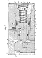
- Fig. 2 shows in a larger scale a portion of the upper end wall, in which a locking device according to the invention is disposed.
- The pneumatic cylinder shown in Fig. 1 comprises, as previously known per se, a
cylinder tube 2, two end walls,namely anupper end wall 3 and a lower end wall 4, apiston 5 displacable between theend walls 3,4 in the cylinder tube, apiston rod 6 connected to thepiston 5, said rod extending sealingly through the lower end wall 4 and carrying at its end a load 7 (e.g.the crust breaker discussed above), as well as connectingports 8 and 9 for the supply of pressurized air to the two cylinder chambers situated between thecylinder piston 5 and theend walls 3 and 4, respectively. - For the operation of the actuating cylinder by means of pressurized air, the connecting
ports 8,9 are connected to each one of two pressure controlled 3-port, 2-position valves Vl and V2, respectively, provided with a return spring (in principal, the valves Vl,V2 can be replaced by one directional valve only, namely a 5-port, 2-position . valve). A pressurized air source K (main pressure, e.g. 3-8 bar) is connected to theinlet ports 1' and 3", respectively, of the valves, while theoutlet ports 2' and 2", respectively, of the valves are connected to connectingparts 8 and 9, respectively, of the actuating cylinder. In the illustrated rest position, wherein the piston is located in its upper end position adjacent to the uppercylinder end wall 3, the pressurized air source K communicates with the lower cylinder chamber via the valve V2, i.e. the chamber between thecylinder piston 5 and the cylinder end wall 4, whereas the upper cylinder chamber (having a negligable volume in the shown position) communicates with the valve outlet 3' via the connecting port 8 and the outlet port 2' of the valve Vl. - If an actuating signal (a certain air pressure) is applied simultaneously on the
control ports 12',12" of the valves, the positions of the valves Vl, V2 are reversed, so that the upper cylinder chamber is instead connected to the pressurized fluid source via the ports 2' and 1' of the valve Vl, whereas the lower cylinder chamber is connected to theoutlet 1" of the valve V2. Hereby, thepiston 5 will perform a downward movement, so that the load 7 is lowered from the fully drawn upper position (minus position) to the dashed lower position (plus position). The load is kept in the lower position as long as the actuating signal is applied on thecontrol ports 12' and 12". As soon as the actuating signal ceases, the valves Vl and V2 are reversed, and thepiston 5 and the load 7 are returned to the upper end position. - As appears further from Fig. 1, the connecting
port 9 of thecylinder 1 communicates with a connectingport 11 in theupper end wall 3 via a conduit orhose 10. Hereby, alocking piston 12 mounted in theend wall 3 is actuated in a way described further below with reference to Fig. 2. - In a radial recess or bore 13 in the cylinder end wall 3 a
sleeve 14 is inserted to perform a guiding means for the above-mentionedlocking piston 12. Radially outside of the guide sleeve 14 and thelocking piston 12, anend plug 15 is screwed therein. Theend plug 15 is provided with a central, through opening 16, in which afilter 17 is inserted between an inner O-ring 18 and an outer locking ring (a s.c. Seeger ring). The through opening 16 of theend plug 15 has internally (i.e. to the left in Fig. 2) a wider portion, theshoulder surface 20 of which forms a seat for apressure spring 21, which urges thelocking piston 12 towards the axis L of the cylinder (dashed), so that in the shown position aninternal locking tongue 22 on thelocking piston 12 is brought into locking engagement with a member connected to thecylinder piston 5, namely alocking flange 23 which is centrally fixed by means of ascrew 24 to aneck 25 protruding axially from thecylinder piston 5. Theupper edge 26 of thelocking flange 23 is bevelled obliquely, and the lower edge 27 of thelocking tongue 22 has a corresponding bevel, though not as steep, so that thelocking flange 23 can be displaced upwards so as to cause thelocking piston 12 to move (towards the right in Fig. 2) against the action of thespring 21, e.g. before transport of thecylinder 1 or in connection with the suspension of a load 7 at the end of the piston rod 6 (see Fig. 1) before connecting the pressurized air. - In order to prevent the
locking piston 12 from rotating about its axis, aguide pin 28 is inserted into the wall of theguide sleeve 14. Theguide pin 28 protrudes into a longitudinal groove 29' in the upper portion of the locking piston. The above-mentioned connectingport 11, communicating with the connectingport 9, is connected to achamber 29 inside theguide sleeve 14, saidchamber 29 being limited on the one hand by anannular shoulder surface 30 of theguide sleeve 14 and on the other hand by anannular piston surface 31 on a widenedportion 32 of thelocking piston 12.Annular sealings chamber 29 is kept pressure separated from the upper cylinder chamber of thecylinder 1 as well as the ambient air. - The locking device operates in the following way: In the rest position according to Fig. 1, the lower cylinder chamber and the
separate chamber 29 communicate with the pressurized air source K, and therefore the locking piston is located in its right hand position not shown in Fig. 2, because thespring 21 is dimensioned so as to be overcome by the pressure exerted by the pressurized air on thepiston surface 31. Now, when an actuating signal is applied to thecontrol ports 12', 12" of the valves Vl,V2, whereby the valves are reversed , the full main pressure is quickly obtained in the upper cylinder chamber of thecylinder 1, since this cylinder chamber has a very small volume. The lower cylinder chamber, however, has a rather large volume and will therefore be emptied relatively slow via theoutlet port 9 and theoutlet 1". - When the pressure difference between the upper and the lower cylinder chambers reaches a certain value, e.g. 0,5-1 bar, the
cylinder piston 5 starts its downward movement. At this moment, however, the lower cylinder chamber and thechamber 29 communicating therewith still have a remaining counter pressure of e.g. 2-3 bar, and therefore thelocking piston 12 is held in its retracted position to the right. Only when the remaining pressure in the last-mentioned chamber has been reduced to a predetermined value, e.g. approximately 1,6 bar, thespring 21 has the power to displace thelocking piston 12 to its left end position. At this time, however, thecylinder piston 5 and itslocking flange 23 have already sunk far down into thecylinder 1, normally all the way down to the lower end position (dashed in Fig. 1). As long as the actuating signal is applied on the valves, the piston 5_ and, consequently, the load 7 as well remain in this lower end position. - As soon as the actuating signal ceases, the valves Vl, V2 are reversed again, whereby the lower cylinder chamber and the separate chamber 29 (now having a rather small volume) quickly reach the air source main pressure of 3-8 bar. Hereby, the
locking piston 12 immediately returns to its retracted right hand position, whereas thecylinder piston 5 together with its load 7 somewhat later reach their upper positionl2(the rest position according to Fig. 1, wherein the locking piston, as mentioned above, is located in its right hand position). - The locking device described above has the following advantages:
- - During normal service conditions, no locking engagement between the
locking piston 12 and thecylinder piston 5 will ever occur, and therefore the wear is reduced to a minimum; - - Each time the
cylinder piston 5 performs an actuating stroke, the locking piston is displaced passively back and forth, and therefore the locking piston is kept operative so that risk of stalling is small; - - When the air pressure disappears (and only then), e.g. due to a hose breakage in the main conduit from the pressurized air source or in one of the conduits which are integrated with the cylinder-valve-system, the
locking piston 12, by the action of thespring 21, will be quickly displaced to its left end position into locking engagement with thelocking flange 23 connected to thecylinder piston 5; - - The area of the
piston surface 31 of thelocking piston 12 and thespring force 21 can easily be so dimensioned that a good safety margine is obtained for the desired functions for a given load and a given main pressure of the pressurized air source; - - The
cylinder piston 5 can be fixedly held in its end position during transport and, moreover, the mounting of the cylinder unit is facilitated, especially in a vertical positon, in that the cylinder piston is locked in a retracted position. - The inventive locking device can be modified in many ways within the scope of the inventive idea defined in
claim 1. Thus, one or more locking pistons can be mounted at each end of the cylinder. Moroever, the locking piston can co-operate with the piston rod instead of thelocking flange 23. Nor is the orientation of the cylinder essential to the invention, though several advantages are gained by the illustraded vertical orientation. The actuating cylinder may be single- acting (by means of a return spring or by way of a load) or double-acting (as described). Finally, the pressurized fluid may be constituted by either oil or gas (air).
Claims (6)
1. A locking device for end postion locking of a cylinder piston (5), which is displacable back and forth between a first and a second cylinder end wall (3,4) in a fluid cylinder (1), comprising at least one locking piston (12), which is movable at an angle to the cylinder axis (L) and which is spring-loaded (21) towards a locking position for engagement with the cylinder piston or a means (23) connected therewith, so that the cylinder piston (5) is locked adjacent to said first cylinder end wall (3), characterized in that the locking piston (12) is operable towards a retracted position by the action of the pressurized fluid exerted on a piston surface (31) on the locking piston in a separate chamber (29), which communicates (10) with the cylinder chamber situated between the cylinder piston (5) and said second cylinder end wall(4), so that, when the cylinder piston (5) is moved away from said first cylinder end wall (3), the residual pressure of the pressurized fluid in said cylinder chamber keeps the locking piston (12) in its retracted position, whereby the locking piston, due to the spring loading, secures the locking of the cylinder piston (5) only in case of a predetermined pressure drop of the pressurized fluid.
2. A locking device as set forth in claim 1, characterized in that the locking piston (12) is slidably mounted in a recess (13) in said first cylinder end wall (3), said separate chamber (29) forming a part of said recess.
3. A locking device as set forth in claim 2, characterized in that the recess (13) is situated in a peripheral part of the cylinder end wall (3), wherein the locking piston (12) in its locking position extends inwardly and engages with said means (23) connected to the cylinder piston (5,25).
4. A locking device as set forth in claim 3, characterized in that said means (23) is arranged on a cylinder piston neck (25), which is displacable into a central cavity in the cylinder end wall (3).
5. A locking device as set forth in anyone of claims 1-4, characterized in that said cylinder chamber (between 5 and 4) and said separate chamber (29) are jointly connected to a pressurized fluid source (K) via a two-posi- tinal valve (V2), which in one of its positions connects said chambers to the pressurized fluid source and in its other position connects said chambers to an outlet (1").
6. A locking device as set forth in claim 5, characterized in that the spring force (21) exerted on the locking piston (12) is dimensioned in such a way that the spring force balances the pressurized fluid pressure exerted on the piston surface (31) of the locking piston at a pressure exceeding the outlet pressure but lying below the pressure of the pressurized fluid source (K).
Applications Claiming Priority (2)
| Application Number | Priority Date | Filing Date | Title |
|---|---|---|---|
| SE8000081A SE8000081L (en) | 1980-01-04 | 1980-01-04 | WASTE MECHANISM FOR PRESSURE CYLINDER |
| SE8000081 | 1980-01-04 |
Publications (1)
| Publication Number | Publication Date |
|---|---|
| EP0032363A1 true EP0032363A1 (en) | 1981-07-22 |
Family
ID=20339893
Family Applications (1)
| Application Number | Title | Priority Date | Filing Date |
|---|---|---|---|
| EP80850194A Withdrawn EP0032363A1 (en) | 1980-01-04 | 1980-12-22 | Locking device for fluid cylinders |
Country Status (5)
| Country | Link |
|---|---|
| EP (1) | EP0032363A1 (en) |
| JP (1) | JPS56501854A (en) |
| NO (1) | NO812829L (en) |
| SE (1) | SE8000081L (en) |
| WO (1) | WO1981002044A1 (en) |
Cited By (3)
| Publication number | Priority date | Publication date | Assignee | Title |
|---|---|---|---|---|
| GB2185532A (en) * | 1986-01-21 | 1987-07-22 | Hydrajaws Limited | Locking fluid power operated devices |
| EP0455012A1 (en) * | 1990-04-30 | 1991-11-06 | Knorr-Bremse Ag | Working cylinder for activation of ventilating and fire protection valves |
| EP1820974A2 (en) | 2006-02-16 | 2007-08-22 | Ross Operating Valve Company | Inlet monitor and latch for a crust breaking system |
Families Citing this family (3)
| Publication number | Priority date | Publication date | Assignee | Title |
|---|---|---|---|---|
| JP4185374B2 (en) * | 2003-01-29 | 2008-11-26 | 株式会社コガネイ | Fluid pressure cylinder |
| FR2948426B1 (en) † | 2009-07-21 | 2011-09-02 | Asco Joucomatic Sa | DEVICE FOR CONTROLLING A PNEUMATIC CYLINDER |
| CN108757634B (en) * | 2018-09-03 | 2024-03-08 | 湖南力得尔智能科技股份有限公司 | Shell pressing cylinder with controllable real-time travel |
Citations (1)
| Publication number | Priority date | Publication date | Assignee | Title |
|---|---|---|---|---|
| US3889576A (en) * | 1969-06-13 | 1975-06-17 | Sheffer Corp | Locking cylinder with improved locking structure |
Family Cites Families (2)
| Publication number | Priority date | Publication date | Assignee | Title |
|---|---|---|---|---|
| US2787252A (en) * | 1955-06-24 | 1957-04-02 | Challenge Machinery Co | Lock for hydraulic piston |
| US3359862A (en) * | 1966-02-25 | 1967-12-26 | Mcdowell Wellman Eng Co | Piston locking means |
-
1980
- 1980-01-04 SE SE8000081A patent/SE8000081L/en not_active Application Discontinuation
- 1980-12-22 WO PCT/SE1980/000349 patent/WO1981002044A1/en not_active Ceased
- 1980-12-22 EP EP80850194A patent/EP0032363A1/en not_active Withdrawn
- 1980-12-22 JP JP50041081A patent/JPS56501854A/ja active Pending
-
1981
- 1981-08-21 NO NO812829A patent/NO812829L/en unknown
Patent Citations (1)
| Publication number | Priority date | Publication date | Assignee | Title |
|---|---|---|---|---|
| US3889576A (en) * | 1969-06-13 | 1975-06-17 | Sheffer Corp | Locking cylinder with improved locking structure |
Cited By (4)
| Publication number | Priority date | Publication date | Assignee | Title |
|---|---|---|---|---|
| GB2185532A (en) * | 1986-01-21 | 1987-07-22 | Hydrajaws Limited | Locking fluid power operated devices |
| EP0455012A1 (en) * | 1990-04-30 | 1991-11-06 | Knorr-Bremse Ag | Working cylinder for activation of ventilating and fire protection valves |
| EP1820974A2 (en) | 2006-02-16 | 2007-08-22 | Ross Operating Valve Company | Inlet monitor and latch for a crust breaking system |
| EP1820974A3 (en) * | 2006-02-16 | 2010-05-19 | Ross Operating Valve Company | Inlet monitor and latch for a crust breaking system |
Also Published As
| Publication number | Publication date |
|---|---|
| NO812829L (en) | 1981-08-21 |
| SE8000081L (en) | 1981-07-05 |
| JPS56501854A (en) | 1981-12-17 |
| WO1981002044A1 (en) | 1981-07-23 |
Similar Documents
| Publication | Publication Date | Title |
|---|---|---|
| US4491154A (en) | Double acting pilot valve | |
| US4671353A (en) | Apparatus for releasing a cementing plug | |
| GB1163920A (en) | Improvements in or relating to Hydropneumatic Suspension Systems | |
| US5649424A (en) | Two-stage pressure cylinder | |
| FI70302C (en) | HYDRAULISK STYRVENTIL | |
| US3633365A (en) | Hydraulic jack | |
| US3997887A (en) | Piston overtravel indicator | |
| GB1491931A (en) | Fluid pressure monitoring safety system | |
| NO143105B (en) | MATT AND RIPFIX, AMORPH FOR CRYSTALLINIC MOVIES OR FILES AND PROCEDURE FOR THEIR PREPARATION | |
| US4188976A (en) | Multiple dental handpiece control system | |
| US4973026A (en) | High pressure water jet cutting nozzle on-off valve | |
| WO1981002044A1 (en) | Locking device for fluid cylinders | |
| CA2024432A1 (en) | Means for receiving and subsequently emptying hydraulic fluid from a hydraulic system | |
| US4256141A (en) | Relay valve for fluid actuators | |
| US3554087A (en) | Hydraulic closing device particularly for injection molding machines | |
| US3149541A (en) | Hydraulically controlled air leg structure | |
| USRE31845E (en) | Relay valve for fluid actuators | |
| AU6700681A (en) | Locking device for fluid cylinders | |
| US3195559A (en) | Spool valve assembly | |
| US4252145A (en) | Manually reset control valve for a fluid actuator | |
| US3983789A (en) | Telescopic props | |
| GB2157771A (en) | Actuator control system | |
| GB2344405A (en) | Directional control vlave with intermediate piston | |
| US3253412A (en) | Aerohydraulic pressure autotransformer for chucks and the like | |
| US3500641A (en) | Pressure intensifying devices |
Legal Events
| Date | Code | Title | Description |
|---|---|---|---|
| PUAI | Public reference made under article 153(3) epc to a published international application that has entered the european phase |
Free format text: ORIGINAL CODE: 0009012 |
|
| AK | Designated contracting states |
Designated state(s): CH DE FR GB IT |
|
| ITCL | It: translation for ep claims filed |
Representative=s name: BARZANO' E ZANARDO MILANO S.P.A. |
|
| DET | De: translation of patent claims | ||
| 17P | Request for examination filed |
Effective date: 19820113 |
|
| STAA | Information on the status of an ep patent application or granted ep patent |
Free format text: STATUS: THE APPLICATION HAS BEEN WITHDRAWN |
|
| 18W | Application withdrawn |
Withdrawal date: 19830211 |
|
| RIN1 | Information on inventor provided before grant (corrected) |
Inventor name: LUNDBERG, KJELL ERIK |