EP0032349B1 - Control device for artificial respirator - Google Patents
Control device for artificial respirator Download PDFInfo
- Publication number
- EP0032349B1 EP0032349B1 EP80401883A EP80401883A EP0032349B1 EP 0032349 B1 EP0032349 B1 EP 0032349B1 EP 80401883 A EP80401883 A EP 80401883A EP 80401883 A EP80401883 A EP 80401883A EP 0032349 B1 EP0032349 B1 EP 0032349B1
- Authority
- EP
- European Patent Office
- Prior art keywords
- oxygen
- time
- during
- flow rate
- inhaling
- Prior art date
- Legal status (The legal status is an assumption and is not a legal conclusion. Google has not performed a legal analysis and makes no representation as to the accuracy of the status listed.)
- Expired
Links
Images

Classifications
-
- A—HUMAN NECESSITIES
- A61—MEDICAL OR VETERINARY SCIENCE; HYGIENE
- A61M—DEVICES FOR INTRODUCING MEDIA INTO, OR ONTO, THE BODY; DEVICES FOR TRANSDUCING BODY MEDIA OR FOR TAKING MEDIA FROM THE BODY; DEVICES FOR PRODUCING OR ENDING SLEEP OR STUPOR
- A61M16/00—Devices for influencing the respiratory system of patients by gas treatment, e.g. mouth-to-mouth respiration; Tracheal tubes
- A61M16/10—Preparation of respiratory gases or vapours
- A61M16/12—Preparation of respiratory gases or vapours by mixing different gases
-
- A—HUMAN NECESSITIES
- A61—MEDICAL OR VETERINARY SCIENCE; HYGIENE
- A61M—DEVICES FOR INTRODUCING MEDIA INTO, OR ONTO, THE BODY; DEVICES FOR TRANSDUCING BODY MEDIA OR FOR TAKING MEDIA FROM THE BODY; DEVICES FOR PRODUCING OR ENDING SLEEP OR STUPOR
- A61M16/00—Devices for influencing the respiratory system of patients by gas treatment, e.g. mouth-to-mouth respiration; Tracheal tubes
- A61M16/021—Devices for influencing the respiratory system of patients by gas treatment, e.g. mouth-to-mouth respiration; Tracheal tubes operated by electrical means
- A61M16/022—Control means therefor
-
- A—HUMAN NECESSITIES
- A61—MEDICAL OR VETERINARY SCIENCE; HYGIENE
- A61M—DEVICES FOR INTRODUCING MEDIA INTO, OR ONTO, THE BODY; DEVICES FOR TRANSDUCING BODY MEDIA OR FOR TAKING MEDIA FROM THE BODY; DEVICES FOR PRODUCING OR ENDING SLEEP OR STUPOR
- A61M16/00—Devices for influencing the respiratory system of patients by gas treatment, e.g. mouth-to-mouth respiration; Tracheal tubes
- A61M16/20—Valves specially adapted to medical respiratory devices
- A61M16/201—Controlled valves
- A61M16/202—Controlled valves electrically actuated
- A61M16/203—Proportional
Definitions
- the present invention relates to an artificial respirator and relates to an electronic control device for such a respirator.
- the device's function is to provide the patient with air often enriched with oxygen, therefore a mixture of air and oxygen, at a rate corresponding to that of breathing and at a slight overpressure (a few tens of millibar, in order to supplement or reinforce the deficient function). It is important to be able to choose precisely the flow rate of the gas mixture to be sent to the patient, the oxygen content of this mixture, the period T of breathing which is imposed on him, and in this period, the inspiration part and the expiration part. (therefore the I / E cyclical ratio).
- a device comprising a mechanical mixer, followed by a flow adjustment needle, the outgoing mixture passing through a solenoid valve controlled by a time base.
- the main disadvantage of such a system is that the flow rate is modified if one acts on the period, or on the O2 content of the mixture, and that it is consequently long and difficult to obtain precise adjustments, which are in particular very difficult to modify during an operation.
- the present invention relates to a control device, the parameters of which can be adjusted completely independently.
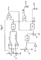
- a control device for an artificial respirator comprises: an air solenoid valve and an oxygen solenoid valve, of the type with variable flow depending on the stroke, supplying in a manifold; a time base with a device for fixing the respiratory rate or period and a device for fixing the ratio of the inspiration time to the expiration time during the breathing period; a mixer, comprising members for fixing the overall respiratory rate and the proportion of oxygen in the gas supplied by the respirator; and two signal generators each assigned to one of the solenoid valves to control their openings; the time base being connected to the generators so that they control the opening of the valves during the inspiration time, the generators being also connected to the mixer to receive the signals corresponding to the amplitudes of the valve openings during the inspiration time , the mixer being connected to the time base to receive a signal corresponding to the ratio of inspiration time to expiration time so as to generate, with the flow rate and proportion indications, signals for the valve openings, such as during the inspiration time, each valve lets in a quantity of gas
- the respirator control device includes an air solenoid valve EV A and an oxygen solenoid valve EVO.
- These solenoid valves are of the variable opening type as a function of the control ampere-turns; they are supplied with air and oxygen under very precise regulated pressures. The air and oxygen flow is therefore a precise function of the opening time and the stroke of the core of each solenoid valve.
- the solenoid valves flow in a tube T, directly connected to the gas supply circuit to the patient, and forming part of the respirator, which in itself is of any conventional type.
- the opening control of each solenoid valve is provided by two identical signal generators G A and G o , each controlling a solenoid valve.
- the time base can also be automatically readjusted by a reaction R, for example from measurements taken on the patient.
- the time base is connected by a line SC to the two generators, to inject them with the same chronological signal. From these signals, the generators control the opening of the solenoid valves during time I, in each time period T.
- the opening amplitudes of the solenoid valves are developed by the generators from signals received from the mixer by the lines M O and M A. These control signals take into account the flow rate of the mixture and the proportion of oxygen, two parameters which are chosen by the operator and a signal linked to I / E, sent by the time base B to the mixer M by the BM line. We can thus obtain a flow rate, with a percentage of oxygen, which is fixed, whatever the values chosen elsewhere by the operator for F and I / S.
- the mixer can also receive external signals for correcting the flow rate and the percentage of oxygen, by lines Cd and Co, for example in the case of automatic monitoring of certain parameters of the patient. Let us consider the parameters to be determined. If we call D T the total flow, air + oxygen, D O and D A the flows of oxygen and air respectively we have: and if we call F O the percentage of oxygen in the mixture we have:
- the mixer is constructed in such a way that one can independently adjust both D T and F o .
- the generation of the electrical signals is carried out in accordance with the present invention from equalities (1) and (2) above.
- the generation of control signals can be established by both an analog and a fully digital process. The latter method may be preferred in the case of automatic control of the parameters from an external regulation source.
- a first potentiometer P 1 is used for fixing by the operator of the percentage of oxygen F O of the mixture.
- a stabilized voltage source V is used with two adjustment resistors, and, using the potentiometer P 1 , a voltage F o between 0.21 volts and 1 volt is chosen, representing the proportion of oxygen between 0 , 21 pure air and 1 pure oxygen.
- the K value is injected into one of the inputs of an inverting adder A 1 , the voltage of 1 volt being injected into the other entry.
- the output of the adder A 1 then gives a value equal to - (1 + K).
- a second potentiometer P 2 is used to fix the total flow.
- the adjustment range P 2 is delimited between 2.5 volts and 0 and the operator can thus choose a voltage V T representative of the total flow of air + mixture oxygen
- a directly proportional signal 1 to I / E coming from the time base B, arriving by the line BM passes in an inverter ( ⁇ 1 then the signal V T and the signal ⁇ I / E are injected into a divider D 2 so to have at the output a signal proportional to the flow that should be obtained during the time of opening of the solenoid valve, that is to say during the inspiration period. Thanks to this operation, the total flow fixed is always independent of the selected I / E ratio. The operator therefore sets the potentiometer P 2 the desired flow rate, without taking care of the I / E ratio and, the divider D 2 determines the instantaneous flow rate as a function of the I / E ratio .
- the output signal from the divider D 2 is sent by a scale adjustment potentiometer P 3 to a divider D 3 which also receives the signal - (1 + K).
- the signal comes out that is to say D O which is taken in contact M O after a potentiometer adjustment.
- the signal is further injected into another divider D 4 receiving the signal K on the other input, from which the signal comes out that is to say D A which is taken at M A after adjustment at the potentiometer.
- FIG. 3 represents a diagram of a generator of analogous signals making the product of the time division signal supplied by the time base and the signal supplied by the gas mixer, so as to supply signals comprising three orders: frequency , duty cycle, amplitude.
- a generator includes a fast switching relay or an analog gate PA, or any equivalent system, controlled by the time base (line SC).
- the signal M (M o or M A ) sent by the mixer is amplified in the AMP amplifier before being injected into the relay.
- the relay output passes through a GCR regulated current generator before attacking the EV solenoid valve.
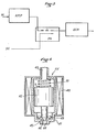
- FIG. 4 shows in schematic section an example of a solenoid valve usable in the device of the present invention.
- the EV solenoid valve comprises a housing 41 in which a core 42 slides.
- the housing comprises a gas inlet 43 and an outlet 44 in which a valve seat 45 is provided.
- a needle 46 cooperates with the seat to close or open more or minus the valve as a function of the number of ampere-turns in the coil 48.
- the outer dimension of the core and the inner dimension of the housing are precisely defined relative to each other to leave a peripheral passage for the gas which is admitted in 43 with a pressure fixed with precision.
- Balls 49 ensure the centering of the needle 46.
- a spring 51 can be provided for the return to the closed position of the valve. In general, the pressure of the gas on the upper face s of the core 42 is sufficient to keep the solenoid valve closed in the absence of excitation of the coil.
- the core 42 is moved towards the inlet 43, by a distance such that a gas flow rate (air is established) or oxygen) via the outlet 46 during the inspiration phase which lets pass a quantity of gas corresponding to the average flow rate during the period 1 + E.
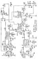
- Figure 5 is an example of a complete circuit diagram of the electronic circuit with indication of the elements and their values.
Description
La présente invention a trait à une respirateur artificiel et a pour objet un dispositif de commande électronique pour un tel respirateur.The present invention relates to an artificial respirator and relates to an electronic control device for such a respirator.
On sait qu'un tel appareil est utilisé pour la respiration forcée d'un patient, notamment pendant qu'il est sous anesthésie au cours d'une opération ou en réanimation ou en unité de soins intensifs par exemple. L'appareil a pour fonction de fournir au patient de l'air souvent enrichi en oxygène, donc un mélange d'air et d'oxygène, à une cadence correspondant à celle de la respiration et à une légère surpression (quelques dizaines de millibar, de façon à suppléer ou renforcer la fonction déficiente). Il est important de pouvoir choisir avec précision le débit du mélange de gaz à envoyer au patient, la teneur en oxygène de ce mélange, la période T de la respiration qui lui est imposée, et dans cette période, la partie inspiration et la partie expiration (donc le rapport cyclique I/E).We know that such a device is used for the forced breathing of a patient, especially while he is under anesthesia during an operation or in intensive care or intensive care unit for example. The device's function is to provide the patient with air often enriched with oxygen, therefore a mixture of air and oxygen, at a rate corresponding to that of breathing and at a slight overpressure (a few tens of millibar, in order to supplement or reinforce the deficient function). It is important to be able to choose precisely the flow rate of the gas mixture to be sent to the patient, the oxygen content of this mixture, the period T of breathing which is imposed on him, and in this period, the inspiration part and the expiration part. (therefore the I / E cyclical ratio).
Jusqu'à présent, on utilise typiquement un dispositif comportant un mélangeur mécanique, suivi d'un pointeau de réglage du débit, le mélange sortant passant par une électrovanne commandée par une base de temps. L'inconvénient principal d'un tel système est que le débit est modifié si l'on agit sur la période, ou sur la teneur en O2 du mélange, et qu'il est par conséquent long et difficile d'obtenir des réglages précis, qui sont en particulier très difficiles à modifier au cours d'une opération.Up to now, a device is typically used comprising a mechanical mixer, followed by a flow adjustment needle, the outgoing mixture passing through a solenoid valve controlled by a time base. The main disadvantage of such a system is that the flow rate is modified if one acts on the period, or on the O2 content of the mixture, and that it is consequently long and difficult to obtain precise adjustments, which are in particular very difficult to modify during an operation.
La présente invention a pour objet un dispositif de commande dont les paramètres peuvent être réglés de façon totalement indépendante.The present invention relates to a control device, the parameters of which can be adjusted completely independently.
Selon la présente invention un dispositif de commande pour respirateur artificiel comprend: une électrovanne d'air et une électrovanne d'oxygène, du type à débit variable en fonction de la course, débitant dans un collecteur; une base de temps avec un organe de fixation de la fréquence ou de la période respiratoire et un organe de fixation du rapport du temps d'inspiration au temps d'expiration pendant la période de la respiration; un mélangeur, comportant des organes de fixation du débit respiratoire global et de la proportion d'oxygène du gaz fourni par le respirateur; et deux générateurs de signaux affectés chacun à une des électrovannes pour commander leurs ouvertures; la base de temps étant connectée aux générateurs pour qu'ils commandent l'ouverture des vannes pendant le temps d'inspiration, les générateurs étant connectés par ailleurs au mélangeur pour recevoir les signaux correspondant aux amplitudes des ouvertures des vannes pendant le temps d'inspiration, le mélangeur étant connecté à la base du temps pour recevoir un signal correspondant au rapport du temps d'inspiration au temps d'expiration de façon à élaborer avec les indications de débit et de proportion, des signaux pour les ouvertures des vannes, tels que pendant le temps inspiration, chaque vanne laisse passer une quantité de gaz correspondant au débit moyen pendant la période de la respiration.According to the present invention, a control device for an artificial respirator comprises: an air solenoid valve and an oxygen solenoid valve, of the type with variable flow depending on the stroke, supplying in a manifold; a time base with a device for fixing the respiratory rate or period and a device for fixing the ratio of the inspiration time to the expiration time during the breathing period; a mixer, comprising members for fixing the overall respiratory rate and the proportion of oxygen in the gas supplied by the respirator; and two signal generators each assigned to one of the solenoid valves to control their openings; the time base being connected to the generators so that they control the opening of the valves during the inspiration time, the generators being also connected to the mixer to receive the signals corresponding to the amplitudes of the valve openings during the inspiration time , the mixer being connected to the time base to receive a signal corresponding to the ratio of inspiration time to expiration time so as to generate, with the flow rate and proportion indications, signals for the valve openings, such as during the inspiration time, each valve lets in a quantity of gas corresponding to the average flow rate during the breathing period.
La description qui va suivre en regard des dessins annexés, donnée à titre d'exemple non limitatif, fera bien comprendre comment l'invention peut être réalisée.
- La figure 1 est un schéma bloc du dispositif selon l'invention,
- La figure 2 est un schéma de montage d'un élément du dispositif de la figure 1 (Mélangeur M),
- La figure 3 est un schéma de montage d'un autre élément du dispositif de la figure 1 (Générateur G),
- La figure 4 est une vue en coupe schématique d'un autre élément constitué par une vanne et,
- La figure 5 est un exemple d'un schéma de montage complet du circuit électronique avec indication des éléments et de leurs valeurs.
- FIG. 1 is a block diagram of the device according to the invention,
- FIG. 2 is an assembly diagram of an element of the device of FIG. 1 (Mixer M),
- FIG. 3 is an assembly diagram of another element of the device of FIG. 1 (Generator G),
- FIG. 4 is a schematic sectional view of another element constituted by a valve and,
- Figure 5 is an example of a complete circuit diagram of the electronic circuit with indication of the elements and their values.
Le dispositif de commande du respirateur artificiel comporte une électrovanne d'air EVA et une électrovanne d'oxygène EVO. Ces électrovannes (voir figure 4 et description en regard) sont du type à ouverture variable en fonction des ampère-tours de commande; elles sont alimentées en air et en oxygène sous des pressions régulées très précises. Le débit d'air et d'oxygène est donc une fonction précise du temps d'ouverture et de la course du noyau de chaque électrovanne. Les électrovannes débitent dans un tube T, directement branché sur le circuit d'alimentation en gaz vers le patient, et faisant partie du respirateur, qui, en lui-même, est d'un type classique quelconque. La commande d'ouverture de chaque électrovanne est assurée par deux générateurs de signaux GA et Go identiques, chacun commandant une électrovanne. Les générateurs GA et Go sont commandés eux-mêmes par une base de temps B, comportant des moyens pour permettre à l'opération de fixer d'une part la fréquence
La base de temps est connectée par une ligne SC aux deux générateurs, pour leur injecter le même signal chronologique. A partir de ces signaux, les générateurs commandent l'ouverture des électrovannes pendant le temps I, dans chaque période de temps T.The time base is connected by a line SC to the two generators, to inject them with the same chronological signal. From these signals, the generators control the opening of the solenoid valves during time I, in each time period T.
Les amplitudes d'ouverture des électrovannes sont élaborées par les générateurs à partir de signaux reçus du mélangeur par les lignes MO et MA. Ces signaux de commande tiennent compte du débit du mélange et de la proportion d'oxygène, deux paramètres qui sont choisis par l'opérateur et d'un signal lié à I/E, envoyé par la base de temps B au mélangeur M par la ligne BM. Ont peut ainsi obtenir un débit, avec un pourcentage en oxygène, qui soit fixe, quelles que soient les valeurs choisies par ailleurs par l'opérateur pour F et I/S.The opening amplitudes of the solenoid valves are developed by the generators from signals received from the mixer by the lines M O and M A. These control signals take into account the flow rate of the mixture and the proportion of oxygen, two parameters which are chosen by the operator and a signal linked to I / E, sent by the time base B to the mixer M by the BM line. We can thus obtain a flow rate, with a percentage of oxygen, which is fixed, whatever the values chosen elsewhere by the operator for F and I / S.
Le mélangeur peut en outre recevoir des signaux extérieurs de correction du débit et du pourcentage en oxygène, par des lignes Cd et Co, par exemple dans le cas d'une surveillance automatique de certains paramètres du patient. Considérons les paramètres à déterminer. Si l'on appelle DT le débit total, air + oxygène, DO et DA les débits d'oxygène et d'air respectivement on a:![]()

![]()
Le mélangeur est constitué de telle manière que l'on puissé régler indépendamment l'une et l'autre DT et Fo. La génération des signaux électriques est réalisée conformément à la présente invention à partir des égalités (1) et (2) ci-dessus. La génération des signaux de commande peut être établie aussi bien par un procédé analogique que totalement numérique. Ce dernier procédé peut être préféré dans le cas d'un pilotage automatique des paramètres à partir d'une source extérieure de régulation.The mixer is constructed in such a way that one can independently adjust both D T and F o . The generation of the electrical signals is carried out in accordance with the present invention from equalities (1) and (2) above. The generation of control signals can be established by both an analog and a fully digital process. The latter method may be preferred in the case of automatic control of the parameters from an external regulation source.
A partir de l'agalité 2, on peut écrire:

Selon une caractéristique de l'invention, la génération des signaux est tirée de ces formules. Une réalisation pratique préférée est preprésentée sur la figure 2. Un premier potentiomètre P1 est utilisé pour la fixation par l'opérateur du pourcentage en oxygène FO du mélange. On utilise une source de tension stabilisée V avec deux résistances de réglage, et, à l'aide du potentiomètre P1, on choisit une tension Fo comprise entre 0,21 volt et 1 volt, représentant la proportion d'oxygène comprise entre 0,21 air pur et 1 oxygène pur. Au moyen de deux soustracteurs S1 et S2, on obtient à partir des trois tensions 0,21, Fo et 1 volt, les tensions représentatives de ―(1 ― FO) et -(Fo = 0,21) que l'on injecte dans le diviseur D1 pour obtenir:
Pour obtenir 1 + K, la valeur K, soit directement, soit après injection dans un multiplicateur recevant une tension de 1 volt, est injectée sur une des entrées d'un additionneur inverseur A1, la tension de 1 volt étant injectée sur l'autre entrée. La sortie de l'additionneur A1 donne une valeur égale alors à -(1 + K).To obtain 1 + K, the K value, either directly or after injection into a multiplier receiving a voltage of 1 volt, is injected into one of the inputs of an inverting adder A 1 , the voltage of 1 volt being injected into the other entry. The output of the adder A 1 then gives a value equal to - (1 + K).
Un deuxième potentiomètre P2 est utilisé pour fixer le débit total. Au moyen d'une résistance et d'une source de tension stabilisée V, on délimite la plage de réglage P2 entre 2,5 volts et 0 et l'opérateur peut ainsi choisir une tension VT représentative du débit total de mélange air + oxygèneA second potentiometer P 2 is used to fix the total flow. By means of a resistor and a stabilized voltage source V, the adjustment range P 2 is delimited between 2.5 volts and 0 and the operator can thus choose a voltage V T representative of the total flow of air + mixture oxygen
Un signal directement proportionnel 1 à I/E issu de la base de temps B, arrivant par la ligne BM passe dans un inverseur (―1 puis le signal VT et le signal ―I/E sont injectés dans un diviseur D2 de façon à avoir à la sortie un signal proportionnel au débit que l'on devra avoir pendant le temps de l'ouverture de l'électrovanne, c'est-à-dire pendant la période d'inspiration. Grâce à cette opération, le débit total fixé est toujours indépendant du rapport I/E choisi. L'opérateur fixe donc le potentiomètre P2 le débit désiré, sans s'occuper du rapport I/E et, le diviseur D2 détermine le débit instantané en fonction du rapport I/E.A directly
Le signal de sortie du diviseur D2 est envoyé par un potentiomètre P3 d'ajustage d'échelle dans une diviseur D3 qui reçoit par ailleurs le signal -(1 + K). Il en sort le signal
Le signal

La figure 3 représente un schéma d'un générateur de signaux analogues faisant le produit du signal de découpage dans le temps fourni par la base de temps et du signal fourni par la mélangeur de gaz, de façon à fournir des signaux comportant trois ordres: fréquence, rapport cyclique, amplitude. Il est rappelé que les deux générateurs GO et GA sont identiques. Un générateur comporte un relais à commutation rapide ou une porte analogique PA, ou tout système équivalent, commandée par la base de temps (ligne SC). Le signal M (Mo ou MA) envoyé par le mélangeur est amplifié dans l'amplficateur AMP avant d'être injecté dans le relais. La sortie du relais traverse un générateur de courant régulé GCR avant d'attaquer l'électrovanne EV.FIG. 3 represents a diagram of a generator of analogous signals making the product of the time division signal supplied by the time base and the signal supplied by the gas mixer, so as to supply signals comprising three orders: frequency , duty cycle, amplitude. It is recalled that the two generators G O and G A are identical. A generator includes a fast switching relay or an analog gate PA, or any equivalent system, controlled by the time base (line SC). The signal M (M o or M A ) sent by the mixer is amplified in the AMP amplifier before being injected into the relay. The relay output passes through a GCR regulated current generator before attacking the EV solenoid valve.
La figure 4 représente en coupe schématique un exemple d'électrovanne utilisable dans la dispositif de la présente invention. L'électrovanne EV comporte un boîtier 41 dans lequel coulisse un noyau 42. Le boîtier comporte une entrée de gaz 43 et une sortie 44 dans laquelle est prévu un siège de clapet 45. Un pointeau 46 coopère avec le siège pour fermer ou ouvrir plus ou moins la vanne en fonction du nombre d'ampère-tours dans la bobine 48. La dimension extérieure du noyau et la dimension intérieure de boîtier sont définies avec précision l'une par rapport à l'autre pour laisser un passage périphérique pour le gas qui est admis en 43 avec une pression fixée avec précision. Des billes 49 assurent le centrage du pointeau 46. On peut prévoir un ressort 51 pour le rappel en position fermée de la vanne. En général la pression du gaz sur la face supérieur s du noyau 42 suffit à maintenir l'électrovanne fermée en l'absence d'excitation de la bobine.Figure 4 shows in schematic section an example of a solenoid valve usable in the device of the present invention. The EV solenoid valve comprises a housing 41 in which a
En fonction du débit affiché, et de la proportion d'oxygène et en fonction du rapport I/E, le noyau 42 est déplacé vers l'entrée 43, d'une distance telle qu'il s'établisse un débit de gaz (air ou oxygène) par la sortie 46 pendant la phase inspiration qui laisse passer une quantité de gaz correspondant au débit moyen pendant la période 1 + E. On réalise bien ainsi les objectifs visés par la présente invention.As a function of the displayed flow rate, and of the proportion of oxygen and as a function of the I / E ratio, the
La figure 5 est un exemple d'un schéma de montage complet du circuit électronique avec indication des éléments et de leurs valeurs.Figure 5 is an example of a complete circuit diagram of the electronic circuit with indication of the elements and their values.
Il va de soi que le mode de réalisation décrit n'est qu'un exemple et qu'il serait possible de le modifier notamment par substitution d'équivalents techniques, sans sortir pour cela du cadre de l'invention.It goes without saying that the embodiment described is only an example and that it would be possible to modify it in particular by substitution of technical equivalents, without departing from the scope of the invention.
Claims (4)
Priority Applications (1)
| Application Number | Priority Date | Filing Date | Title |
|---|---|---|---|
| AT80401883T ATE4283T1 (en) | 1980-01-04 | 1980-12-29 | CONTROL DEVICE FOR ARTIFICIAL RESPIRATOR. |
Applications Claiming Priority (2)
| Application Number | Priority Date | Filing Date | Title |
|---|---|---|---|
| FR8000096 | 1980-01-04 | ||
| FR8000096A FR2472937A1 (en) | 1980-01-04 | 1980-01-04 | ARTIFICIAL RESPIRATOR CONTROL DEVICE |
Publications (2)
| Publication Number | Publication Date |
|---|---|
| EP0032349A1 EP0032349A1 (en) | 1981-07-22 |
| EP0032349B1 true EP0032349B1 (en) | 1983-07-27 |
Family
ID=9237203
Family Applications (1)
| Application Number | Title | Priority Date | Filing Date |
|---|---|---|---|
| EP80401883A Expired EP0032349B1 (en) | 1980-01-04 | 1980-12-29 | Control device for artificial respirator |
Country Status (12)
| Country | Link |
|---|---|
| US (1) | US4380233A (en) |
| EP (1) | EP0032349B1 (en) |
| JP (1) | JPS56109667A (en) |
| AR (1) | AR225339A1 (en) |
| AT (1) | ATE4283T1 (en) |
| BR (1) | BR8008604A (en) |
| CA (1) | CA1158344A (en) |
| DE (1) | DE3064459D1 (en) |
| ES (1) | ES8201420A1 (en) |
| FR (1) | FR2472937A1 (en) |
| IL (1) | IL61790A (en) |
| MX (1) | MX149343A (en) |
Families Citing this family (30)
| Publication number | Priority date | Publication date | Assignee | Title |
|---|---|---|---|---|
| FR2513885B1 (en) * | 1981-10-05 | 1986-09-05 | Tech Atlantique Centre | IMPROVEMENT OF VOLUMETRIC CUT ANESTHESIA RESPIRATORS |
| US4471773A (en) * | 1981-11-19 | 1984-09-18 | Bunnell Life System, Inc. | Apparatus and method for delivering medication to patient's respiratory system |
| FR2548549B1 (en) * | 1983-07-08 | 1988-09-23 | Asm Sud Europe | GAS MIXER FOR MEDICAL USE |
| JPS60122154U (en) * | 1984-01-26 | 1985-08-17 | シャープ株式会社 | artificial respirator |
| US4587967A (en) * | 1985-07-09 | 1986-05-13 | Lifecare Services, Inc. | Oxygen enriched reciprocating piston respirator |
| US4747403A (en) * | 1986-01-27 | 1988-05-31 | Advanced Pulmonary Technologies, Inc. | Multi-frequency jet ventilation technique and apparatus |
| US4838259A (en) * | 1986-01-27 | 1989-06-13 | Advanced Pulmonary Technologies, Inc. | Multi-frequency jet ventilation technique and apparatus |
| US5092326A (en) * | 1987-11-19 | 1992-03-03 | Winn Bryan D | Apparatus and method for a ventilator system |
| US4986268A (en) * | 1988-04-06 | 1991-01-22 | Tehrani Fleur T | Method and apparatus for controlling an artificial respirator |
| DE3817985A1 (en) * | 1988-05-27 | 1989-12-07 | Salvia Werk Gmbh | DEVICE FOR SUPPORTING THE SPONTANEOUS BREATHING OF A PATIENT |
| US5299568A (en) * | 1989-06-22 | 1994-04-05 | Puritan-Bennett Corporation | Method for controlling mixing and delivery of respiratory gas |
| US5038771A (en) * | 1990-01-25 | 1991-08-13 | Dietz Henry G | Method and apparatus for respiratory therapy using intermittent flow having automatic adjustment of a dose of therapeutic gas to the rate of breathing |
| EP0520082A1 (en) * | 1991-06-28 | 1992-12-30 | Siemens-Elema AB | Ventilator in which the inspiratory flow rate is controlled by the expiratory flow rate |
| DE59208797D1 (en) * | 1992-05-21 | 1997-09-18 | Siemens Ag | Method and device for controlling and independently monitoring a very small glass flow |
| WO1996024402A1 (en) * | 1995-02-08 | 1996-08-15 | Puritan-Bennett Corporation | Gas mixing apparatus for a ventilator |
| JP2001516623A (en) * | 1997-09-19 | 2001-10-02 | レスピロニックス・インコーポレイテッド | Medical respirator |
| US6192883B1 (en) * | 1999-08-03 | 2001-02-27 | Richard L. Miller, Jr. | Oxygen flow control system and method |
| WO2006058354A1 (en) | 2004-12-01 | 2006-06-08 | Carl Reiner Gmbh | Method for providing gas mixtures for respirators and method for carrying out said method |
| US20080202521A1 (en) * | 2007-02-23 | 2008-08-28 | General Electric Company | Setting mandatory mechanical ventilation parameters based on patient physiology |
| US20080202518A1 (en) * | 2007-02-23 | 2008-08-28 | General Electric Company | Setting mandatory mechanical ventilation parameters based on patient physiology |
| US20080202517A1 (en) * | 2007-02-23 | 2008-08-28 | General Electric Company | Setting madatory mechanical ventilation parameters based on patient physiology |
| US20080202520A1 (en) * | 2007-02-23 | 2008-08-28 | General Electric Company | Setting mandatory mechanical ventilation parameters based on patient physiology |
| US20080202519A1 (en) * | 2007-02-23 | 2008-08-28 | General Electric Company | Setting mandatory mechanical ventilation parameters based on patient physiology |
| US20080230063A1 (en) * | 2007-03-23 | 2008-09-25 | General Electric Company | Setting inspiratory time in mandatory mechanical ventilation based on patient physiology, such as forced inhalation time |
| US20080230064A1 (en) * | 2007-03-23 | 2008-09-25 | General Electric Company | Setting inspiratory time in mandatory mechanical ventilation based on patient physiology, such as when forced inhalation flow ceases |
| US20080230060A1 (en) * | 2007-03-23 | 2008-09-25 | General Electric Company | Setting inspiratory time in mandatory mechanical ventilation based on patient physiology, such as when tidal volume is inspired |
| US20080230061A1 (en) * | 2007-03-23 | 2008-09-25 | General Electric Company | Setting expiratory time in mandatory mechanical ventilation based on a deviation from a stable condition of end tidal gas concentrations |
| US8656913B2 (en) * | 2007-06-05 | 2014-02-25 | Allied Healthcare Products, Inc. | Ventilator apparatus |
| CN102114295B (en) * | 2009-12-31 | 2013-10-23 | 北京谊安医疗系统股份有限公司 | Oxygen mixing method for electric respirator |
| KR101138959B1 (en) | 2010-02-17 | 2012-04-25 | 주식회사 멕 아이씨에스 | Pneumatic block apparatus of medical ventilator |
Family Cites Families (4)
| Publication number | Priority date | Publication date | Assignee | Title |
|---|---|---|---|---|
| GB914343A (en) * | 1959-02-06 | 1963-01-02 | Pye Ltd | Electronic time cycled respirator |
| GB1338226A (en) * | 1970-01-21 | 1973-11-21 | British Oxygen Co Ltd | Lung ventilators |
| GB1288019A (en) * | 1971-08-19 | 1972-09-06 | ||
| NL7707259A (en) * | 1977-06-30 | 1979-01-03 | Philips Nv | RESPIRATOR. |
-
1980
- 1980-01-04 FR FR8000096A patent/FR2472937A1/en active Granted
- 1980-12-22 IL IL61790A patent/IL61790A/en unknown
- 1980-12-27 JP JP18940180A patent/JPS56109667A/en active Pending
- 1980-12-29 EP EP80401883A patent/EP0032349B1/en not_active Expired
- 1980-12-29 DE DE8080401883T patent/DE3064459D1/en not_active Expired
- 1980-12-29 AT AT80401883T patent/ATE4283T1/en active
- 1980-12-30 AR AR283846A patent/AR225339A1/en active
- 1980-12-30 ES ES498237A patent/ES8201420A1/en not_active Expired
- 1980-12-30 BR BR8008604A patent/BR8008604A/en unknown
- 1980-12-30 US US06/221,469 patent/US4380233A/en not_active Expired - Fee Related
- 1980-12-31 CA CA000367759A patent/CA1158344A/en not_active Expired
-
1981
- 1981-01-05 MX MX185443A patent/MX149343A/en unknown
Also Published As
| Publication number | Publication date |
|---|---|
| IL61790A0 (en) | 1981-01-30 |
| EP0032349A1 (en) | 1981-07-22 |
| MX149343A (en) | 1983-10-24 |
| ATE4283T1 (en) | 1983-08-15 |
| BR8008604A (en) | 1981-07-28 |
| FR2472937A1 (en) | 1981-07-10 |
| CA1158344A (en) | 1983-12-06 |
| US4380233A (en) | 1983-04-19 |
| IL61790A (en) | 1983-07-31 |
| JPS56109667A (en) | 1981-08-31 |
| ES498237A0 (en) | 1981-12-16 |
| DE3064459D1 (en) | 1983-09-01 |
| ES8201420A1 (en) | 1981-12-16 |
| AR225339A1 (en) | 1982-03-15 |
| FR2472937B1 (en) | 1984-05-25 |
Similar Documents
| Publication | Publication Date | Title |
|---|---|---|
| EP0032349B1 (en) | Control device for artificial respirator | |
| EP0042321B1 (en) | Respirator with automatic ventilation correction | |
| FR2675050A1 (en) | METHOD FOR CALIBRATING A FLOW SENSOR IN A RESPIRATORY SYSTEM. | |
| WO2007068849A2 (en) | Respiratory anaesthesia apparatus with device for measuring the xenon concentration | |
| EP1502619A1 (en) | Device for supplying a specific pressure or volume of breathing gas | |
| DE3529547C2 (en) | ||
| EP0969894B1 (en) | Variable orifice pulse valve | |
| EP0589751A1 (en) | Installation and procedure to deliver a gas mixture into the airways of a customer | |
| EP0098193B1 (en) | Flow meter mixer for supplying a mixture of two gases, the proportion of which may not be lower than a given value | |
| FR2624744A1 (en) | METHOD FOR REGULATING AN ARTIFICIAL VENTILATION DEVICE AND SUCH A DEVICE | |
| FR2573311A1 (en) | ARTIFICIAL VENTILATION APPARATUS COMPRISING A VOLUMETRIC INSPIRATORY ASSISTANCE DEVICE | |
| US3923461A (en) | Apparatus and method employing gas-permeable membrane for separating, diluting, or concentrating molecular species | |
| DE8319573U1 (en) | DEVICE FOR THE TREATMENT OF A PATIENT'S BREATHABILITY | |
| FR2976812A1 (en) | OXYGEN DOSING DEVICE FOR ANESTHESIA APPARATUS | |
| EP2803379B1 (en) | Apparatus for artificial ventilation having an absolute pressure sensor and a differential pressure sensor | |
| CH618602A5 (en) | Installation for ventilating a patient | |
| FR2877228A1 (en) | METHOD OF OPERATING AN ANESTHESIA APPARATUS | |
| FR2574538A1 (en) | ELECTRONIC ASSEMBLY AND CALIBRATION METHOD FOR HOT-WIRE FLOWMETER | |
| DE2931647C2 (en) | Device for determining the influence of gaseous components of a gas flow by dilution and / or diffusion | |
| US6155256A (en) | Fresh gas system and a method for vaporizing a liquid anaesthetic | |
| EP0392502B1 (en) | Method and apparatus for measuring a parameter of a gas in isolation from gas pressure fluctuations | |
| DE2750450B2 (en) | Ventilator | |
| FR3023488A1 (en) | METHOD FOR IMPROVED DISTRIBUTION OF A GAS MIXTURE OF MEDICAL OXYGEN O2 AND ANOTHER MEDICAL GAS | |
| JP2776065B2 (en) | Gas chromatograph sample introduction method | |
| FR2911281A1 (en) | Gas e.g. nitrogen monoxide, injection device for treating pulmonary hypertension of patient, has pressure sensor for measuring gas pressure in gas passage between passage restriction unit and solenoid valves |
Legal Events
| Date | Code | Title | Description |
|---|---|---|---|
| PUAI | Public reference made under article 153(3) epc to a published international application that has entered the european phase |
Free format text: ORIGINAL CODE: 0009012 |
|
| AK | Designated contracting states |
Designated state(s): AT BE CH DE FR GB IT LU NL SE |
|
| 17P | Request for examination filed |
Effective date: 19810810 |
|
| RAP1 | Party data changed (applicant data changed or rights of an application transferred) |
Owner name: SYNTHELABO |
|
| ITF | It: translation for a ep patent filed |
Owner name: DR. ING. A. RACHELI & C. |
|
| GRAA | (expected) grant |
Free format text: ORIGINAL CODE: 0009210 |
|
| AK | Designated contracting states |
Designated state(s): AT BE CH DE FR GB IT LI LU NL SE |
|
| REF | Corresponds to: |
Ref document number: 4283 Country of ref document: AT Date of ref document: 19830815 Kind code of ref document: T |
|
| REF | Corresponds to: |
Ref document number: 3064459 Country of ref document: DE Date of ref document: 19830901 |
|
| PG25 | Lapsed in a contracting state [announced via postgrant information from national office to epo] |
Ref country code: LU Free format text: LAPSE BECAUSE OF NON-PAYMENT OF DUE FEES Effective date: 19831231 |
|
| PLBE | No opposition filed within time limit |
Free format text: ORIGINAL CODE: 0009261 |
|
| STAA | Information on the status of an ep patent application or granted ep patent |
Free format text: STATUS: NO OPPOSITION FILED WITHIN TIME LIMIT |
|
| 26N | No opposition filed | ||
| PGFP | Annual fee paid to national office [announced via postgrant information from national office to epo] |
Ref country code: FR Payment date: 19841123 Year of fee payment: 5 |
|
| PGFP | Annual fee paid to national office [announced via postgrant information from national office to epo] |
Ref country code: AT Payment date: 19841127 Year of fee payment: 5 |
|
| PGFP | Annual fee paid to national office [announced via postgrant information from national office to epo] |
Ref country code: CH Payment date: 19841218 Year of fee payment: 5 |
|
| PGFP | Annual fee paid to national office [announced via postgrant information from national office to epo] |
Ref country code: SE Payment date: 19841231 Year of fee payment: 5 Ref country code: NL Payment date: 19841231 Year of fee payment: 5 Ref country code: BE Payment date: 19841231 Year of fee payment: 5 |
|
| PGFP | Annual fee paid to national office [announced via postgrant information from national office to epo] |
Ref country code: DE Payment date: 19850227 Year of fee payment: 5 |
|
| PG25 | Lapsed in a contracting state [announced via postgrant information from national office to epo] |
Ref country code: AT Effective date: 19851229 |
|
| PG25 | Lapsed in a contracting state [announced via postgrant information from national office to epo] |
Ref country code: SE Effective date: 19851230 |
|
| PG25 | Lapsed in a contracting state [announced via postgrant information from national office to epo] |
Ref country code: LI Effective date: 19851231 Ref country code: CH Effective date: 19851231 Ref country code: BE Effective date: 19851231 |
|
| BERE | Be: lapsed |
Owner name: SYNTHELABO Effective date: 19851231 |
|
| PG25 | Lapsed in a contracting state [announced via postgrant information from national office to epo] |
Ref country code: NL Effective date: 19860701 |
|
| GBPC | Gb: european patent ceased through non-payment of renewal fee | ||
| NLV4 | Nl: lapsed or anulled due to non-payment of the annual fee | ||
| PG25 | Lapsed in a contracting state [announced via postgrant information from national office to epo] |
Ref country code: FR Free format text: LAPSE BECAUSE OF NON-PAYMENT OF DUE FEES Effective date: 19860829 |
|
| REG | Reference to a national code |
Ref country code: CH Ref legal event code: PL |
|
| PG25 | Lapsed in a contracting state [announced via postgrant information from national office to epo] |
Ref country code: DE Effective date: 19860902 |
|
| REG | Reference to a national code |
Ref country code: FR Ref legal event code: ST |
|
| PG25 | Lapsed in a contracting state [announced via postgrant information from national office to epo] |
Ref country code: GB Effective date: 19881118 |
|
| PGFP | Annual fee paid to national office [announced via postgrant information from national office to epo] |
Ref country code: LU Payment date: 19930105 Year of fee payment: 13 |
|
| EPTA | Lu: last paid annual fee | ||
| EUG | Se: european patent has lapsed |
Ref document number: 80401883.6 Effective date: 19860902 |