EP0032347A2 - Automatische Sprühvorrichtung für den Sicherheitsbehälter eines Druckwasserreaktors - Google Patents
Automatische Sprühvorrichtung für den Sicherheitsbehälter eines Druckwasserreaktors Download PDFInfo
- Publication number
- EP0032347A2 EP0032347A2 EP80401880A EP80401880A EP0032347A2 EP 0032347 A2 EP0032347 A2 EP 0032347A2 EP 80401880 A EP80401880 A EP 80401880A EP 80401880 A EP80401880 A EP 80401880A EP 0032347 A2 EP0032347 A2 EP 0032347A2
- Authority
- EP
- European Patent Office
- Prior art keywords
- auxiliary tank
- tank
- liquid
- tube
- circuit
- Prior art date
- Legal status (The legal status is an assumption and is not a legal conclusion. Google has not performed a legal analysis and makes no representation as to the accuracy of the status listed.)
- Granted
Links
Images
Classifications
-
- G—PHYSICS
- G21—NUCLEAR PHYSICS; NUCLEAR ENGINEERING
- G21C—NUCLEAR REACTORS
- G21C9/00—Emergency protection arrangements structurally associated with the reactor, e.g. safety valves provided with pressure equalisation devices
- G21C9/004—Pressure suppression
- G21C9/012—Pressure suppression by thermal accumulation or by steam condensation, e.g. ice condensers
-
- Y—GENERAL TAGGING OF NEW TECHNOLOGICAL DEVELOPMENTS; GENERAL TAGGING OF CROSS-SECTIONAL TECHNOLOGIES SPANNING OVER SEVERAL SECTIONS OF THE IPC; TECHNICAL SUBJECTS COVERED BY FORMER USPC CROSS-REFERENCE ART COLLECTIONS [XRACs] AND DIGESTS
- Y02—TECHNOLOGIES OR APPLICATIONS FOR MITIGATION OR ADAPTATION AGAINST CLIMATE CHANGE
- Y02E—REDUCTION OF GREENHOUSE GAS [GHG] EMISSIONS, RELATED TO ENERGY GENERATION, TRANSMISSION OR DISTRIBUTION
- Y02E30/00—Energy generation of nuclear origin
- Y02E30/30—Nuclear fission reactors
Definitions
- the present invention relates to a passive device for automatically spraying a liquid such as water possibly containing chemical additives in the confinement enclosure of a pressurized water reactor when the pressure in the enclosure reaches a given value.
- emergency systems consist of sprinkling circuits comprising pumps connected to the electrical network backed up.
- these known systems have various drawbacks. First of all, they are active systems whose implementation is conditioned by the operation of electrically controlled elements such as pumps and solenoid valves. In addition, these systems involve significant start-up delays, generally of the order of 100 seconds after the triggering of the spray signal.
- the subject of the present invention is a device for spraying the containment of a pressurized water reactor which does not have the drawbacks of the prior devices and in particular ensuring automatic and instantaneous spraying of the enclosure, without this spraying is conditioned by the operation of a solenoid valve, a pump or an electrical supply circuit, due to the entirely passive nature of this device.
- an automatic spraying device for the confinement enclosure of a pressurized water reactor when the pressure in the enclosure reaches a given maximum value, this device being characterized in what it includes a main tank and an auxiliary tank of smaller volume sensitive to the pressure prevailing in the enclosure, the two tanks being filled with a spraying liquid so that the level of the liquid in the auxiliary tank is lower than that of the liquid in the main tank, these two tanks being connected by a first inverted U tube forming a siphon, a second inverted U tube forming a siphon, the elbow of which is disposed above the level of the auxiliary tank, connecting the latter to a spray nozzle ramp located below the bottom of the auxiliary tank and inside the containment.
- the spraying device when the pressure rises inside the containment due to an accident by rupture of the primary circuit or by rupture of a piping of steam inside this enclosure, the siphon formed by the first inverted U-shaped tube is automatically primed as soon as the pressure in the enclosure exceeds a given value.
- the water contained in the main tank then pours into the auxiliary tank until the level of the latter comes up to the elbow formed by the second inverted U-shaped tube.
- This rise in the level of the liquid in the auxiliary tank is very rapid due to the small volume of this tank.
- the siphon formed by the second U-shaped tube is then primed in turn and the water contained in the auxiliary tank is sprayed inside the enclosure by the boom of spray nozzles.
- the device according to the invention is therefore entirely passive and automatic and the spraying by the spray nozzles takes place within a very short time.
- this device comprises a closed tank defining the main tank and the auxiliary tank is received inside this tank, for example against the wall.
- the normal level of the liquid in the main tank can then be determined by the height of the walls of the auxiliary tank.
- the auxiliary tank communicates with a leveling circuit provided with at least one normally closed valve and the opening of which makes it possible to fix the level of liquid in the auxiliary tank.
- the first U-shaped tube is connected to a venting circuit allowing, during the initial filling, to be on the water level in the two branches of the tube.
- the section of the branch of the first U-shaped tube disposed in the auxiliary tank is greater than the section of the other branch of this tube.
- the increase in diameter of the branch of the U-shaped tube disposed in the auxiliary tank or the existence of a buffer volume on the venting branch makes it possible to limit the increase in the pressure of the volume of air trapped in the tube when the liquid rises in the branch of the tube which opens into the main tank, which allows, at the same starting pressure, to increase the height difference between the top of the U-shaped tube and the water level in the first tank.
- the device comprises a liquid supply circuit opening into the main tank and provided with at least one normally closed valve.
- the supply of water to the reservoir is then preferably done via an open tube in the enclosure at the top, thus allowing the pressure to be balanced between the enclosure and the tank. , this tube being terminated by a bend in the lower part so as to retain a water plug isolating the atmospheres of the enclosure and of the cover and preventing any evaporation of the water from the cover.
- a normal pump spraying circuit can be connected to the supply piping downstream of the valve.
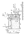
- the device shown in the single figure is arranged entirely inside the confinement enclosure (not shown) of a pressurized water nuclear reactor. It comprises a closed cover 10, of height H l , in which is disposed, preferably against the wall of the cover l0, a small auxiliary tank 12 whose height H 2 is less than the height H 1 of the cover 10.
- the volume of the small tank 12 is very small compared to the volume of the main tank 18 defined by the cover 10 outside the small tank 12.
- a supply circuit 14 opens out above the main tank 18 via a J-shaped tube 15 open at its upper end and terminated by a bend at its lower end which opens into the tank 18, so to retain a water plug isolating the atmospheres of the enclosure and the cover and ensuring pressure balancing by avoiding any evaporation of the water contained in the cover.
- the circuit 14 comprises at least one valve 16 making it possible to fill the reservoir 18 with water possibly containing chemical additives. Due to the limited height H 2 of the side walls of the reservoir 12, the supply circuit 14 also makes it possible to overfill the auxiliary reservoir 12 when the level of the water contained in the main reservoir 18 arrives at the top of the side walls of the tank 12.
- a conventional spraying circuit 17 comprising at least one pump 19 can be advantageously connected to the circuit 14 downstream of the valve 16.
- a leveling circuit 20 opening at its highest level in the auxiliary tank 12 and comprising at least one valve 22 makes it possible to limit the level in the auxiliary tank to a height H 3 substantially lower than the height H 2 of the water in the main tank.
- a first inverted U-shaped tube forming a siphon 24 is disposed astride the side wall of the tank 12 so as to immerse by a branch 26 in the main tank and by a branch 28 in the auxiliary tank.
- the elbow of the tube 24 is placed at a distance h l above the surface of the water in the main tank 18.
- the elbow of the tube 24 is in communication with a venting circuit 32 controlled by a pump 34 which is opened for a short time in order to balance the pressures at the end of filling.
- the air volume can be increased between the two levels of the first siphon, either by widening the section of the branch 28 which plunges into the reservoir 12 as shown in solid lines in the figure, or by placing a buffer volume 30 on the venting circuit 32 as shown in dashed lines in the figure.
- the spray device according to the invention also comprises a second inverted U-shaped tube forming a siphon 36, a first branch 38 of which communicates with the auxiliary tank 12 at the bottom of the latter and the second branch of which communicates with a nozzle ramp spray 42.
- the elbow of the U-shaped tube 36 is located at a distance h 2 above the level of the water in the auxiliary tank 12, this level being determined by the leveling circuit 20.
- the automatic spraying device which has just been described with reference to the single figure operates in the following manner.
- the main tank 18 and the auxiliary tank 12 are normally filled by the supply circuit 14 at levels determined respectively by the height of the side walls of the auxiliary tank 12 and by the height of the mouth of the circuit 20 in the reservoir 12, the valves 16 and 22 being open simultaneously during filling.
- the valve 34 is also open for a short time to balance the pressures between the tank and the air volume of the first siphon.
- valves 16, 22 and 34 are closed.
- the main tank 18 and the auxiliary tank 12 are filled as illustrated in the figure, and the siphons formed by the inverted U-shaped tubes 24 and 36 are defused.
- the pressure prevailing inside the sealed enclosure is applied to the water contained in the tanks via the J-tube 15. Given the water plug formed in the end of the tube 15, it can differ very slightly from the pressure inside the tank.
- the water contained in the main tank 18 is automatically discharged through the tube 24 into the auxiliary tank 12. It this results in an increase in the level of the water in the reservoir 12 which rapidly causes the water to rise in the branch 38 of the U-shaped tube 36 above the elbow of the latter.
- the siphon defined by the tube 36 is thus primed and the water from the auxiliary tank is poured through the ramp of spray nozzles 42 inside the confinement enclosure to condense the vapor formed and lower the pressure in the 'pregnant.
- the spray device according to the invention is therefore started automatically and the increase in pressure in the enclosure remains limited without it being necessary to trigger a solenoid valve or a pump whose operation is always conditioned by the possible failure of their control circuits.
- This spraying device is therefore entirely passive and does not have the drawbacks of the devices of the prior art fulfilling similar functions.
- the main tank defined in the tank 10 can be replenished at any time by means of pumps from the recirculation of the drains accumulated in the sump of the enclosure to constitute a part of the circuit of conventional spray 17.
- the invention is not limited to the embodiment which has just been described by way of example, but covers all its variants.
- the arrangement of the main tank and the auxiliary tank inside a single tank is not not essential to the invention and it will be understood that these two tanks can be constituted by two separate and preferably adjacent tanks, the filling of the auxiliary tank then no longer taking place by overflow or even through a piping of liaison.
Landscapes
- Physics & Mathematics (AREA)
- Engineering & Computer Science (AREA)
- Plasma & Fusion (AREA)
- General Engineering & Computer Science (AREA)
- High Energy & Nuclear Physics (AREA)
- Structure Of Emergency Protection For Nuclear Reactors (AREA)
- Nozzles (AREA)
Applications Claiming Priority (2)
| Application Number | Priority Date | Filing Date | Title |
|---|---|---|---|
| FR8000843 | 1980-01-15 | ||
| FR8000843A FR2473774B1 (fr) | 1980-01-15 | 1980-01-15 | Dispositif d'aspersion automatique de l'enceinte de confinement d'un reacteur a eau pressurisee |
Publications (3)
| Publication Number | Publication Date |
|---|---|
| EP0032347A2 true EP0032347A2 (de) | 1981-07-22 |
| EP0032347A3 EP0032347A3 (en) | 1981-08-05 |
| EP0032347B1 EP0032347B1 (de) | 1985-06-05 |
Family
ID=9237558
Family Applications (1)
| Application Number | Title | Priority Date | Filing Date |
|---|---|---|---|
| EP80401880A Expired EP0032347B1 (de) | 1980-01-15 | 1980-12-29 | Automatische Sprühvorrichtung für den Sicherheitsbehälter eines Druckwasserreaktors |
Country Status (5)
| Country | Link |
|---|---|
| EP (1) | EP0032347B1 (de) |
| CA (1) | CA1153786A (de) |
| DE (1) | DE3070749D1 (de) |
| ES (1) | ES8301049A1 (de) |
| FR (1) | FR2473774B1 (de) |
Cited By (3)
| Publication number | Priority date | Publication date | Assignee | Title |
|---|---|---|---|---|
| WO1997004460A1 (en) * | 1995-07-20 | 1997-02-06 | Finmeccanica S.P.A. Azienda Ansaldo | Depressurization system for pressurized steam operated plant |
| US6071482A (en) * | 1997-05-28 | 2000-06-06 | Forschungszentrum Julich Gmbh | Device for cooling and intermixing of gas from accidental leaks |
| WO2004093093A3 (de) * | 2003-04-16 | 2005-01-06 | Framatome Anp Gmbh | Kerntechnische anlage und verfahren zum betrieb einer kerntechnischen anlage |
Families Citing this family (1)
| Publication number | Priority date | Publication date | Assignee | Title |
|---|---|---|---|---|
| KR101473377B1 (ko) | 2013-05-09 | 2014-12-24 | 한국원자력연구원 | 피동격납건물살수계통 |
Family Cites Families (6)
| Publication number | Priority date | Publication date | Assignee | Title |
|---|---|---|---|---|
| DE1146598B (de) * | 1961-06-14 | 1963-04-04 | Siemens Ag | Sicherheitseinrichtung fuer die Gebaeude von Leistungskernreaktoren |
| FR1477135A (fr) * | 1965-08-09 | 1967-04-14 | Ca Atomic Energy Ltd | Système d'isolement pour réacteurs nucléaires |
| SE316847B (de) * | 1968-03-28 | 1969-11-03 | Asea Ab | |
| US3566904A (en) * | 1969-04-15 | 1971-03-02 | Atomic Energy Commission | Liquid flow control system |
| US3718539A (en) * | 1971-03-31 | 1973-02-27 | Combustion Eng | Passive nuclear reactor safeguard system |
| SU537389A1 (ru) * | 1974-06-05 | 1976-11-30 | Всесоюзный Дважды Ордена Трудового Красного Знамени Теплотехнический Научно-Исследовательский Институт Им.Ф.Э.Дзержинского | Система ограничени последствий аварии на атомных электростанци х |
-
1980
- 1980-01-15 FR FR8000843A patent/FR2473774B1/fr not_active Expired
- 1980-12-29 DE DE8080401880T patent/DE3070749D1/de not_active Expired
- 1980-12-29 EP EP80401880A patent/EP0032347B1/de not_active Expired
-
1981
- 1981-01-09 CA CA000368216A patent/CA1153786A/en not_active Expired
- 1981-01-14 ES ES498493A patent/ES8301049A1/es not_active Expired
Cited By (4)
| Publication number | Priority date | Publication date | Assignee | Title |
|---|---|---|---|---|
| WO1997004460A1 (en) * | 1995-07-20 | 1997-02-06 | Finmeccanica S.P.A. Azienda Ansaldo | Depressurization system for pressurized steam operated plant |
| US5943384A (en) * | 1995-07-20 | 1999-08-24 | Finmeccanica S.P.A. Azienda Ansaldo | Depressurization system for pressurized steam operated plant |
| US6071482A (en) * | 1997-05-28 | 2000-06-06 | Forschungszentrum Julich Gmbh | Device for cooling and intermixing of gas from accidental leaks |
| WO2004093093A3 (de) * | 2003-04-16 | 2005-01-06 | Framatome Anp Gmbh | Kerntechnische anlage und verfahren zum betrieb einer kerntechnischen anlage |
Also Published As
| Publication number | Publication date |
|---|---|
| FR2473774A1 (fr) | 1981-07-17 |
| EP0032347B1 (de) | 1985-06-05 |
| CA1153786A (en) | 1983-09-13 |
| FR2473774B1 (fr) | 1986-01-10 |
| ES498493A0 (es) | 1982-11-01 |
| ES8301049A1 (es) | 1982-11-01 |
| EP0032347A3 (en) | 1981-08-05 |
| DE3070749D1 (en) | 1985-07-11 |
Similar Documents
| Publication | Publication Date | Title |
|---|---|---|
| CA2159097C (fr) | Systeme de regulation d'air pour reservoir hydropneumatique | |
| EP0206874B1 (de) | Kunststoffkraftstoffbehälter, insbesondere für Kraftfahrzeuge | |
| FR2672100A1 (fr) | Vanne de coupure automatique a deux etages. | |
| EP0029372B1 (de) | Notkühlsystem für den Kern eines Druckwasserkernreaktors | |
| EP0032347B1 (de) | Automatische Sprühvorrichtung für den Sicherheitsbehälter eines Druckwasserreaktors | |
| EP0177400B1 (de) | Schwimmende Behälterdecke eines Speichertanks insbesondere verwendet in einer Elektronuklearanlage | |
| EP2110597B1 (de) | Vorrichtung und Verfahren der Luftzufuhr in einen hydropneumatischen Behälter | |
| EP0026705B1 (de) | Notkühlvorrichtung für den Kern eines Druckwasserreaktors | |
| FR2657373A1 (fr) | Dispositif de curage d'un canal. | |
| EP0178210B1 (de) | Schwimmende Behälterdecke eines Speichertanks insbesondere verwendet in einer Elektronuklearanlage | |
| WO1983001086A1 (fr) | Systeme pour empecher l'entrainement de liquides au nez de torche | |
| KR830002545B1 (ko) | 자동 스프링클러 | |
| EP0895020B1 (de) | Vorrichtung zur Einführung von Luft in einem hydropneumatischen Vorratsbehälter | |
| FR2739170A1 (fr) | Reservoir hydropneumatique anti-belier avec dispositif d'admission et de regulation d'air, procede d'admission d'air | |
| EP0341149B1 (de) | Kompensationeinrichtung durch Abfluss einer bestimmten Ersatzflüssigkeit und Anwendung zur Wiederbelieferung eines hydraulischen Kreises | |
| FR2570683A1 (fr) | Perfectionnement aux reservoirs a toit flottant pour liquides, notamment aux reservoirs de stockage utilises dans le domaine electronucleaire | |
| FR2596786A1 (fr) | Dispositif de vidage d'un reservoir de liquide, notamment dispositif de chasse d'eau pour cuvette de w.c. | |
| FR2694622A1 (fr) | Procédé et dispositif permettant de contrôler, en service, le fonctionnement de détecteurs de niveau d'eau, notamment dans une chaudière à vapeur. | |
| WO2025109460A1 (fr) | Système de chasse d'eau silencieux muni d'un siphon | |
| FR2515747A1 (fr) | Dispositif de pompage, notamment pour refouler des fluides toxiques | |
| FR3162431A1 (fr) | Dispositif de traitement d’au moins un liquide comprenant au moins une colonne à dépression et un récolteur de mousse équipé d’un système de vidange gravitaire fonctionnant par dépression | |
| FR2751625A1 (fr) | Dispositif flotteur de securite pour cuvette de retention d'hydrocarbures | |
| FR2618210A1 (fr) | Appareil antigel. | |
| FR2575740A1 (fr) | Dispositif perfectionne pour le transvasement et le degazage de liquide | |
| BE489902A (de) |
Legal Events
| Date | Code | Title | Description |
|---|---|---|---|
| PUAI | Public reference made under article 153(3) epc to a published international application that has entered the european phase |
Free format text: ORIGINAL CODE: 0009012 |
|
| PUAL | Search report despatched |
Free format text: ORIGINAL CODE: 0009013 |
|
| AK | Designated contracting states |
Designated state(s): BE CH DE GB IT NL SE |
|
| AK | Designated contracting states |
Designated state(s): BE CH DE GB IT NL SE |
|
| 17P | Request for examination filed |
Effective date: 19820109 |
|
| ITF | It: translation for a ep patent filed | ||
| GRAA | (expected) grant |
Free format text: ORIGINAL CODE: 0009210 |
|
| AK | Designated contracting states |
Designated state(s): BE CH DE GB IT LI NL SE |
|
| REF | Corresponds to: |
Ref document number: 3070749 Country of ref document: DE Date of ref document: 19850711 |
|
| PLBE | No opposition filed within time limit |
Free format text: ORIGINAL CODE: 0009261 |
|
| STAA | Information on the status of an ep patent application or granted ep patent |
Free format text: STATUS: NO OPPOSITION FILED WITHIN TIME LIMIT |
|
| 26N | No opposition filed | ||
| PGFP | Annual fee paid to national office [announced via postgrant information from national office to epo] |
Ref country code: NL Payment date: 19871231 Year of fee payment: 8 |
|
| PGFP | Annual fee paid to national office [announced via postgrant information from national office to epo] |
Ref country code: CH Payment date: 19890111 Year of fee payment: 9 |
|
| PG25 | Lapsed in a contracting state [announced via postgrant information from national office to epo] |
Ref country code: SE Effective date: 19891230 |
|
| PG25 | Lapsed in a contracting state [announced via postgrant information from national office to epo] |
Ref country code: LI Effective date: 19891231 Ref country code: CH Effective date: 19891231 Ref country code: BE Effective date: 19891231 |
|
| BERE | Be: lapsed |
Owner name: COMMISSARIAT A L'ENERGIE ATOMIQUE ETABLISSEMENT D Effective date: 19891231 |
|
| PG25 | Lapsed in a contracting state [announced via postgrant information from national office to epo] |
Ref country code: NL Effective date: 19900701 |
|
| NLV4 | Nl: lapsed or anulled due to non-payment of the annual fee | ||
| REG | Reference to a national code |
Ref country code: CH Ref legal event code: PL |
|
| PGFP | Annual fee paid to national office [announced via postgrant information from national office to epo] |
Ref country code: DE Payment date: 19911122 Year of fee payment: 12 |
|
| PGFP | Annual fee paid to national office [announced via postgrant information from national office to epo] |
Ref country code: GB Payment date: 19911223 Year of fee payment: 12 |
|
| ITTA | It: last paid annual fee | ||
| PG25 | Lapsed in a contracting state [announced via postgrant information from national office to epo] |
Ref country code: GB Effective date: 19921229 |
|
| GBPC | Gb: european patent ceased through non-payment of renewal fee |
Effective date: 19921229 |
|
| PG25 | Lapsed in a contracting state [announced via postgrant information from national office to epo] |
Ref country code: DE Effective date: 19930901 |
|
| EUG | Se: european patent has lapsed |
Ref document number: 80401880.2 Effective date: 19900829 |