EP0032347A2 - Automatic sprinkler device for the containment of a pressurized-water reactor - Google Patents
Automatic sprinkler device for the containment of a pressurized-water reactor Download PDFInfo
- Publication number
- EP0032347A2 EP0032347A2 EP80401880A EP80401880A EP0032347A2 EP 0032347 A2 EP0032347 A2 EP 0032347A2 EP 80401880 A EP80401880 A EP 80401880A EP 80401880 A EP80401880 A EP 80401880A EP 0032347 A2 EP0032347 A2 EP 0032347A2
- Authority
- EP
- European Patent Office
- Prior art keywords
- auxiliary tank
- tank
- liquid
- tube
- circuit
- Prior art date
- Legal status (The legal status is an assumption and is not a legal conclusion. Google has not performed a legal analysis and makes no representation as to the accuracy of the status listed.)
- Granted
Links
Images
Classifications
-
- G—PHYSICS
- G21—NUCLEAR PHYSICS; NUCLEAR ENGINEERING
- G21C—NUCLEAR REACTORS
- G21C9/00—Emergency protection arrangements structurally associated with the reactor, e.g. safety valves provided with pressure equalisation devices
- G21C9/004—Pressure suppression
- G21C9/012—Pressure suppression by thermal accumulation or by steam condensation, e.g. ice condensers
-
- Y—GENERAL TAGGING OF NEW TECHNOLOGICAL DEVELOPMENTS; GENERAL TAGGING OF CROSS-SECTIONAL TECHNOLOGIES SPANNING OVER SEVERAL SECTIONS OF THE IPC; TECHNICAL SUBJECTS COVERED BY FORMER USPC CROSS-REFERENCE ART COLLECTIONS [XRACs] AND DIGESTS
- Y02—TECHNOLOGIES OR APPLICATIONS FOR MITIGATION OR ADAPTATION AGAINST CLIMATE CHANGE
- Y02E—REDUCTION OF GREENHOUSE GAS [GHG] EMISSIONS, RELATED TO ENERGY GENERATION, TRANSMISSION OR DISTRIBUTION
- Y02E30/00—Energy generation of nuclear origin
- Y02E30/30—Nuclear fission reactors
Definitions
- the present invention relates to a passive device for automatically spraying a liquid such as water possibly containing chemical additives in the confinement enclosure of a pressurized water reactor when the pressure in the enclosure reaches a given value.
- emergency systems consist of sprinkling circuits comprising pumps connected to the electrical network backed up.
- these known systems have various drawbacks. First of all, they are active systems whose implementation is conditioned by the operation of electrically controlled elements such as pumps and solenoid valves. In addition, these systems involve significant start-up delays, generally of the order of 100 seconds after the triggering of the spray signal.
- the subject of the present invention is a device for spraying the containment of a pressurized water reactor which does not have the drawbacks of the prior devices and in particular ensuring automatic and instantaneous spraying of the enclosure, without this spraying is conditioned by the operation of a solenoid valve, a pump or an electrical supply circuit, due to the entirely passive nature of this device.
- an automatic spraying device for the confinement enclosure of a pressurized water reactor when the pressure in the enclosure reaches a given maximum value, this device being characterized in what it includes a main tank and an auxiliary tank of smaller volume sensitive to the pressure prevailing in the enclosure, the two tanks being filled with a spraying liquid so that the level of the liquid in the auxiliary tank is lower than that of the liquid in the main tank, these two tanks being connected by a first inverted U tube forming a siphon, a second inverted U tube forming a siphon, the elbow of which is disposed above the level of the auxiliary tank, connecting the latter to a spray nozzle ramp located below the bottom of the auxiliary tank and inside the containment.
- the spraying device when the pressure rises inside the containment due to an accident by rupture of the primary circuit or by rupture of a piping of steam inside this enclosure, the siphon formed by the first inverted U-shaped tube is automatically primed as soon as the pressure in the enclosure exceeds a given value.
- the water contained in the main tank then pours into the auxiliary tank until the level of the latter comes up to the elbow formed by the second inverted U-shaped tube.
- This rise in the level of the liquid in the auxiliary tank is very rapid due to the small volume of this tank.
- the siphon formed by the second U-shaped tube is then primed in turn and the water contained in the auxiliary tank is sprayed inside the enclosure by the boom of spray nozzles.
- the device according to the invention is therefore entirely passive and automatic and the spraying by the spray nozzles takes place within a very short time.
- this device comprises a closed tank defining the main tank and the auxiliary tank is received inside this tank, for example against the wall.
- the normal level of the liquid in the main tank can then be determined by the height of the walls of the auxiliary tank.
- the auxiliary tank communicates with a leveling circuit provided with at least one normally closed valve and the opening of which makes it possible to fix the level of liquid in the auxiliary tank.
- the first U-shaped tube is connected to a venting circuit allowing, during the initial filling, to be on the water level in the two branches of the tube.
- the section of the branch of the first U-shaped tube disposed in the auxiliary tank is greater than the section of the other branch of this tube.
- the increase in diameter of the branch of the U-shaped tube disposed in the auxiliary tank or the existence of a buffer volume on the venting branch makes it possible to limit the increase in the pressure of the volume of air trapped in the tube when the liquid rises in the branch of the tube which opens into the main tank, which allows, at the same starting pressure, to increase the height difference between the top of the U-shaped tube and the water level in the first tank.
- the device comprises a liquid supply circuit opening into the main tank and provided with at least one normally closed valve.
- the supply of water to the reservoir is then preferably done via an open tube in the enclosure at the top, thus allowing the pressure to be balanced between the enclosure and the tank. , this tube being terminated by a bend in the lower part so as to retain a water plug isolating the atmospheres of the enclosure and of the cover and preventing any evaporation of the water from the cover.
- a normal pump spraying circuit can be connected to the supply piping downstream of the valve.
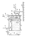
- the device shown in the single figure is arranged entirely inside the confinement enclosure (not shown) of a pressurized water nuclear reactor. It comprises a closed cover 10, of height H l , in which is disposed, preferably against the wall of the cover l0, a small auxiliary tank 12 whose height H 2 is less than the height H 1 of the cover 10.
- the volume of the small tank 12 is very small compared to the volume of the main tank 18 defined by the cover 10 outside the small tank 12.
- a supply circuit 14 opens out above the main tank 18 via a J-shaped tube 15 open at its upper end and terminated by a bend at its lower end which opens into the tank 18, so to retain a water plug isolating the atmospheres of the enclosure and the cover and ensuring pressure balancing by avoiding any evaporation of the water contained in the cover.
- the circuit 14 comprises at least one valve 16 making it possible to fill the reservoir 18 with water possibly containing chemical additives. Due to the limited height H 2 of the side walls of the reservoir 12, the supply circuit 14 also makes it possible to overfill the auxiliary reservoir 12 when the level of the water contained in the main reservoir 18 arrives at the top of the side walls of the tank 12.
- a conventional spraying circuit 17 comprising at least one pump 19 can be advantageously connected to the circuit 14 downstream of the valve 16.
- a leveling circuit 20 opening at its highest level in the auxiliary tank 12 and comprising at least one valve 22 makes it possible to limit the level in the auxiliary tank to a height H 3 substantially lower than the height H 2 of the water in the main tank.
- a first inverted U-shaped tube forming a siphon 24 is disposed astride the side wall of the tank 12 so as to immerse by a branch 26 in the main tank and by a branch 28 in the auxiliary tank.
- the elbow of the tube 24 is placed at a distance h l above the surface of the water in the main tank 18.
- the elbow of the tube 24 is in communication with a venting circuit 32 controlled by a pump 34 which is opened for a short time in order to balance the pressures at the end of filling.
- the air volume can be increased between the two levels of the first siphon, either by widening the section of the branch 28 which plunges into the reservoir 12 as shown in solid lines in the figure, or by placing a buffer volume 30 on the venting circuit 32 as shown in dashed lines in the figure.
- the spray device according to the invention also comprises a second inverted U-shaped tube forming a siphon 36, a first branch 38 of which communicates with the auxiliary tank 12 at the bottom of the latter and the second branch of which communicates with a nozzle ramp spray 42.
- the elbow of the U-shaped tube 36 is located at a distance h 2 above the level of the water in the auxiliary tank 12, this level being determined by the leveling circuit 20.
- the automatic spraying device which has just been described with reference to the single figure operates in the following manner.
- the main tank 18 and the auxiliary tank 12 are normally filled by the supply circuit 14 at levels determined respectively by the height of the side walls of the auxiliary tank 12 and by the height of the mouth of the circuit 20 in the reservoir 12, the valves 16 and 22 being open simultaneously during filling.
- the valve 34 is also open for a short time to balance the pressures between the tank and the air volume of the first siphon.
- valves 16, 22 and 34 are closed.
- the main tank 18 and the auxiliary tank 12 are filled as illustrated in the figure, and the siphons formed by the inverted U-shaped tubes 24 and 36 are defused.
- the pressure prevailing inside the sealed enclosure is applied to the water contained in the tanks via the J-tube 15. Given the water plug formed in the end of the tube 15, it can differ very slightly from the pressure inside the tank.
- the water contained in the main tank 18 is automatically discharged through the tube 24 into the auxiliary tank 12. It this results in an increase in the level of the water in the reservoir 12 which rapidly causes the water to rise in the branch 38 of the U-shaped tube 36 above the elbow of the latter.
- the siphon defined by the tube 36 is thus primed and the water from the auxiliary tank is poured through the ramp of spray nozzles 42 inside the confinement enclosure to condense the vapor formed and lower the pressure in the 'pregnant.
- the spray device according to the invention is therefore started automatically and the increase in pressure in the enclosure remains limited without it being necessary to trigger a solenoid valve or a pump whose operation is always conditioned by the possible failure of their control circuits.
- This spraying device is therefore entirely passive and does not have the drawbacks of the devices of the prior art fulfilling similar functions.
- the main tank defined in the tank 10 can be replenished at any time by means of pumps from the recirculation of the drains accumulated in the sump of the enclosure to constitute a part of the circuit of conventional spray 17.
- the invention is not limited to the embodiment which has just been described by way of example, but covers all its variants.
- the arrangement of the main tank and the auxiliary tank inside a single tank is not not essential to the invention and it will be understood that these two tanks can be constituted by two separate and preferably adjacent tanks, the filling of the auxiliary tank then no longer taking place by overflow or even through a piping of liaison.
Abstract
Description
La présente invention concerne un dispositif passif permettant de pulvériser automatiquement un liquide tel que de l'eau contenant éventuellement des additifs chimiques dans l'enceinte de confinement d'un réacteur à eau pressurisée lorsque la pression dans l'enceinte atteint une valeur donnée.The present invention relates to a passive device for automatically spraying a liquid such as water possibly containing chemical additives in the confinement enclosure of a pressurized water reactor when the pressure in the enclosure reaches a given value.
Dans le cas d'un accident par rupture du circuit primaire ou par rupture d'une tuyauterie de vapeur à l'intérieur de l'enceinte de confinement du réacteur, la pression et la température dans l'enceinte ont tendance à monter et de l'iode peut être libérée.In the event of an accident by rupture of the primary circuit or by rupture of a steam pipe inside the containment of the reactor, the pressure and the temperature in the containment tend to rise and l iodine can be released.
Afin de maintenir constamment la pression et la température dans l'enceinte en-dessous d'une certaine valeur et de rabattre l'iode éventuellement libérée, on prévoit généralement des systèmes de secours qui se composent de circuits d'aspersion comportant des pompes reliées au réseau électrique secouru. Cependant, ces systèmes connus présentent différents inconvénients. Tout d'abord, il s'agit de systèmes actifs dont la mise en oeuvre est conditionnée par le fonctionnement d'éléments commandés électriquement tels que des pompes et des électrovannes. De plus, ces systèmes impliquent des délais de mise en route importants, généralement de l'ordre de 100 secondes après le déclenchement du signal d'aspersion.In order to constantly maintain the pressure and the temperature in the enclosure below a certain value and to reduce any iodine released, emergency systems are generally provided which consist of sprinkling circuits comprising pumps connected to the electrical network backed up. However, these known systems have various drawbacks. First of all, they are active systems whose implementation is conditioned by the operation of electrically controlled elements such as pumps and solenoid valves. In addition, these systems involve significant start-up delays, generally of the order of 100 seconds after the triggering of the spray signal.
La présente invention a pour objet un dispositif d'aspersion de l'enceinte de confinement d'un réacteur à eau pressurisée ne présentant pas les inconvénients des dispositifs antérieurs et assurant notamment une aspersion automatique et instantanée de l'enceinte, sans que cette aspersion ne soit conditionnée par le fonctionnement d'une électrovanne, d'une pompe ou d'un circuit électrique d'alimentation, en raison du caractère entièrement passif de ce dispositif.The subject of the present invention is a device for spraying the containment of a pressurized water reactor which does not have the drawbacks of the prior devices and in particular ensuring automatic and instantaneous spraying of the enclosure, without this spraying is conditioned by the operation of a solenoid valve, a pump or an electrical supply circuit, due to the entirely passive nature of this device.
A cet effet et conformément à l'invention, il est proposé un dispositif d'aspersion automatique de l'enceinte de confinement d'un réacteur à eau pressurisée lorsque la pression dans l'enceinte atteint une valeur maximale donnée, ce dispositif étant caractérisé en ce qu'il comprend un réservoir principal et un réservoir auxiliaire de plus petit volume sensibles à la pression régnant dans l'enceinte, les deux réservoirs étant remplis d'un liquide d'aspersion de telle sorte que le niveau du liquide dans le réservoir auxiliaire est inférieur à celui du liquide dans le réservoir principal, ces deux réservoirs étant reliés par un premier tube en U renversé formant siphon, un second tube en U renversé formant siphon, dont le coude est disposé au-dessus du niveau du réservoir auxiliaire, reliant ce dernier à une rampe de buses d'aspersion située en-dessous du fond du réservoir auxiliaire et à l'intérieur de l'enceinte de confinement.To this end and in accordance with the invention, an automatic spraying device is proposed for the confinement enclosure of a pressurized water reactor when the pressure in the enclosure reaches a given maximum value, this device being characterized in what it includes a main tank and an auxiliary tank of smaller volume sensitive to the pressure prevailing in the enclosure, the two tanks being filled with a spraying liquid so that the level of the liquid in the auxiliary tank is lower than that of the liquid in the main tank, these two tanks being connected by a first inverted U tube forming a siphon, a second inverted U tube forming a siphon, the elbow of which is disposed above the level of the auxiliary tank, connecting the latter to a spray nozzle ramp located below the bottom of the auxiliary tank and inside the containment.
Grâce au dispositif d'aspersion dont les caractéristiques essentielles viennent d'être énoncées, lorsque la pression s'élève à l'intérieur de l'enceinte de confinement en raison d'un accident par rupture du circuit primaire ou par rupture d'une tuyauterie de vapeur à l'intérieur de cette enceinte, le siphon formé par le premier tube en U renversé est amorcé automatiquement dès que la pression dans l'enceinte dépasse une valeur donnée. L'eau contenue dans le réservoir principal se déverse alors dans le réservoir auxiliaire jusqu'à ce que le niveau de ce dernier vienne à la hauteur du coude formé par le second tube en U renversé. Cette élévation du niveau du liquide dans le réservoir auxiliaire est très rapide en raison du faible volume de ce réservoir. Le siphon formé par le second tube en U est alors amorcé à son tour et l'eau contenue dans le réservoir auxiliaire est pulvérisée à l'intérieur de l'enceinte par la rampe de buses d'aspersion. Le dispositif selon l'invention est donc entièrement passif et automatique et la pulvérisation par les buses d'aspersion intervient dans un délai très court.Thanks to the spraying device, the essential characteristics of which have just been stated, when the pressure rises inside the containment due to an accident by rupture of the primary circuit or by rupture of a piping of steam inside this enclosure, the siphon formed by the first inverted U-shaped tube is automatically primed as soon as the pressure in the enclosure exceeds a given value. The water contained in the main tank then pours into the auxiliary tank until the level of the latter comes up to the elbow formed by the second inverted U-shaped tube. This rise in the level of the liquid in the auxiliary tank is very rapid due to the small volume of this tank. The siphon formed by the second U-shaped tube is then primed in turn and the water contained in the auxiliary tank is sprayed inside the enclosure by the boom of spray nozzles. The device according to the invention is therefore entirely passive and automatic and the spraying by the spray nozzles takes place within a very short time.
Dans un mode de réalisation préféré de l'invention, ce dispositif comprend une bâche fermée définissant le réservoir principal et le réservoir auxiliaire est reçu à l'intérieur de cette bâche, par exemple contre la paroi. Le niveau normal du liquide dans le réservoir principal peut alors être déterminé par la hauteur des parois du réservoir auxiliaire.In a preferred embodiment of the invention, this device comprises a closed tank defining the main tank and the auxiliary tank is received inside this tank, for example against the wall. The normal level of the liquid in the main tank can then be determined by the height of the walls of the auxiliary tank.
Conformément à une caractéristique secondaire de l'invention, le réservoir auxiliaire communique avec un circuit de mise à niveau muni d'au moins une vanne normalement fermée et dont l'ouverture permet de fixer le niveau de liquide dans le réservoir auxiliaire.In accordance with a secondary characteristic of the invention, the auxiliary tank communicates with a leveling circuit provided with at least one normally closed valve and the opening of which makes it possible to fix the level of liquid in the auxiliary tank.
De préférence, le premier tube en U est relié à un circuit d'éventage permettant, lors du remplissage initial, d'être sur du niveau d'eau dans les deux branches du tube.Preferably, the first U-shaped tube is connected to a venting circuit allowing, during the initial filling, to be on the water level in the two branches of the tube.
Dans une première variante de l'invention, la section de la branche du premier tube en U disposée dans le réservoir auxiliaire est supérieure à la section de l'autre branche de ce tube.In a first variant of the invention, the section of the branch of the first U-shaped tube disposed in the auxiliary tank is greater than the section of the other branch of this tube.
Dans une seconde variante de l'invention, on dispose sur le circuit d'éventage du premier tube en U un volume tampon.In a second variant of the invention, there is a buffer volume on the venting circuit of the first U-shaped tube.
L'augmentation de diamètre de la branche du tube en U disposée dans le réservoir auxiliaire ou l'existence d'un volume tampon sur la branche d'éventage permettent de limiter l'augmentation de la pression du volume d'air emprisonné dans le tube lorsque le liquide monte dans la branche du tube qui débouche dans le réservoir principal, ce qui permet, à même pression d'amorçage, d'augmenter la différence de hauteur entre le sommet du tube en U et le niveau d'eau dans le premier réservoir.The increase in diameter of the branch of the U-shaped tube disposed in the auxiliary tank or the existence of a buffer volume on the venting branch makes it possible to limit the increase in the pressure of the volume of air trapped in the tube when the liquid rises in the branch of the tube which opens into the main tank, which allows, at the same starting pressure, to increase the height difference between the top of the U-shaped tube and the water level in the first tank.
Selon encore une autre caractéristique secondaire de l'invention, le dispositif comprend un circuit d'alimentation en liquide débouchant dans le réservoir principal et muni d'au moins une vanne normalement fermée. L'arrivée dans le réservoir de l'eau d'alimentation se fait alors de préférence par l'intermédiaire d'un tube ouvert dans l'enceinte en partie supérieure, permettant ainsi l'équilibrage de la pression entre l'enceinte et la bâche, ce tube étant terminé par un coude en partie inférieure de façon à retenir un bouchon d'eau isolant les atmosphères de l'enceinte et de la bâche et évitant toute évaporation de l'eau de la bâche. Un circuit normal d'aspersion par pompes peut être branché sur la tuyauterie d'alimentation en aval de la vanne.According to yet another secondary characteristic of the invention, the device comprises a liquid supply circuit opening into the main tank and provided with at least one normally closed valve. The supply of water to the reservoir is then preferably done via an open tube in the enclosure at the top, thus allowing the pressure to be balanced between the enclosure and the tank. , this tube being terminated by a bend in the lower part so as to retain a water plug isolating the atmospheres of the enclosure and of the cover and preventing any evaporation of the water from the cover. A normal pump spraying circuit can be connected to the supply piping downstream of the valve.
On décrira maintenant, à titre d'exemple non limitatif, un mode de réalisation particulier de l'invention en se référant au dessin annexé dans lequel la figure unique représente de façon schématique un dispositif d'aspersion automatique de l'enceinte de confinement d'un réacteur à eau pressurisée réalisé conformément aux enseignements de la présente invention.A particular embodiment of the invention will now be described, by way of nonlimiting example, with reference to the appended drawing in which the single figure schematically represents an automatic spraying device for the containment enclosure of a pressurized water reactor produced in accordance with the teachings of the present invention.
Le dispositif représenté sur la figure unique est disposé entièrement à l'intérieur de l'enceinte de confinement (non représentée) d'un réacteur nucléaire à eau pressurisée. Il comprend une bâche fermée 10, de hauteur Hl, dans laquelle est disposé, de préférence contre la paroi de la bâche l0,un petit réservoir auxiliaire 12 dont la hauteur H2 est inférieure à la hauteur H1 de la bâche 10. Le volume du petit réservoir 12 est très petit par rapport au volume du réservoir principal 18 défini par la bâche 10 en dehors du petit réservoir 12.The device shown in the single figure is arranged entirely inside the confinement enclosure (not shown) of a pressurized water nuclear reactor. It comprises a closed
Un circuit d'alimentation 14 débouche au-dessus du réservoir principal 18 par l'intermédiaire d'un tube 15 en forme de J ouvert à son extrémité supérieure et terminé par un coude à son extrémité inférieure qui débouche dans le réservoir 18, de façon à retenir un bouchon d'eau isolant les atmosphères de l'enceinte et de la bâche et assurant l'équilibrage des pressions en évitant toute évaporation de l'eau contenue dans la bâche. Le circuit 14 comprend au moins une vanne 16 permettant de remplir le réservoir 18 d'eau contenant éventuellement des additifs chimiques. En raison de la hauteur limitée H2 des parois latérales du réservoir 12, le circuit d'alimentation 14 permet également de remplir par trop-plein le réservoir auxiliaire 12 lorsque le niveau de l'eau contenue dans le réservoir principal 18 arrive en haut des parois latérales du réservoir 12.A
Un circuit d'aspersion classique 17 comprenant au moins une pompe 19 peut être branché de façon avantageuse sur le circuit 14 en aval de la vanne 16.A
Un circuit de mise à niveau 20 débouchant à son niveau le plus haut dans le réservoir auxiliaire 12 et comprenant au moins une vanne 22 permet de limiter le niveau dans le réservoir auxiliaire à une hauteur H3 sensiblement inférieure à la hauteur H2 de l'eau dans le réservoir principal.A
Pour éviter tout amorçage intempestif de l'aspersion, le remplissage, c'est-à-dire l'ouverture de la vanne 16 est en principe empêché tant que la vanne 22 n'est pas complètement ouverte.To avoid any untimely initiation of spraying, filling, that is to say the opening of the
Un premier tube en U renversé et formant siphon 24 est disposé à cheval sur la paroi latérale du réservoir 12 de façon à plonger par une branche 26 dans le réservoir principal et par une branche 28 dans le réservoir auxiliaire. Le coude du tube 24 est placé à une distance hl au-dessus de la surface de l'eau dans le réservoir principal 18.A first inverted U-shaped tube forming a
Le coude du tube 24 est en communication avec un circuit d'éventage 32 contrôlé par une pompe 34 qui est ouverte un bref instant afin d'équilibrer les pressions à la fin du remplissage.The elbow of the
S'il est nécessaire d'accroître la garde hl pour une pression d'amorçage du siphon donnée, on peut augmenter le volume d'air entre les deux niveaux du premier siphon, soit en élargissant la section de la branche 28 qui plonge dans le réservoir 12 comme on l'a représenté en traits pleins sur la figure, soit en plaçant un volume tampon 30 sur le circuit d'éventage 32 comme on l'a représenté en traits mixtes sur la figure.If it is necessary to increase the clearance h l for a given priming pressure of the siphon, the air volume can be increased between the two levels of the first siphon, either by widening the section of the
Bien que les deux variantes de réalisation qui viennent d'être décrites soient représentées simultanément sur la figure unique, on comprendra qu'elles constituent deux alternatives de réalisation qui sont normalement choisies indépendamment l'une de l'autre.Although the two alternative embodiments which have just been described are shown simultaneously in the single figure, it will be understood that they constitute two alternative embodiments which are normally chosen independently of one another.
Le dispositif d'aspersion selon l'invention comprend également un second tube en U renversé formant siphon 36 dont une première branche 38 communique avec le réservoir auxiliaire 12 à la partie inférieure de ce dernier et dont la seconde branche 40 communique avec une rampe de buses d'aspersion 42. De plus, le coude du tube en U 36 est situé à une distance h2 au-dessus du niveau de l'eau dans le réservoir auxiliaire 12, ce niveau étant déterminé par le circuit de mise à niveau 20.The spray device according to the invention also comprises a second inverted U-shaped tube forming a
Le dispositif d'aspersion automatique que l'on vient de décrire en se référant à la figure unique fonctionne de la façon suivante.The automatic spraying device which has just been described with reference to the single figure operates in the following manner.
Comme il a été décrit précédemment, le réservoir principal 18 et le réservoir auxiliaire 12 sont normalement remplis par le circuit d'alimentation 14 à des niveaux déterminés respectivement par la hauteur des parois latérales du réservoir auxiliaire 12 et par la hauteur de l'embouchure du circuit 20 dans le réservoir 12, les vannes 16 et 22 étant ouvertes simultanément au cours du remplissage. A la fin du remplissage, la vanne 34 est elle aussi ouverte un bref instant pour équilibrer les pressions entre la bâche et le volume d'air du premier siphon.As described above, the
Lors du fonctionnement normal du réacteur, les vannes 16, 22 et 34 sont fermées. Le réservoir principal 18 et le réservoir auxiliaire 12 sont remplis comme l'illustre la figure, et les siphons formés par les tubes en U renversés 24 et 36 sont désamorcés. La pression régnant à l'intérieur de l'enceinte étanche est appliquée à l'eau contenue dans les réservoirs par l'intermédiaire du tube en J 15. Compte tenu du bouchon d'eau formé dans l'extrémité du tube 15, elle peut différer très légèrement de la pression régnant à l'intérieur de la bâche.During normal operation of the reactor, the
Lorsqu'un accident par rupture d'un circuit primaire ou par rupture d'une tuyauterie de vapeur à l'intérieur de l'enceinte étanche du réacteur se produit, la pression à l'intérieur de l'enceinte tend à augmenter. L'ensemble du dispositif d'aspersion selon l'invention étant placé à l'intérieur de l'enceinte, cette augmentation de pression chasse le bouchon d'eau du tube 15 et s'applique à la surface libre de l'eau dans le réservoir principal 18 et dans le réservoir auxiliaire 12. Il en résulte une montée de l'eau dans les branches 26 et 28 du tube en U 24. Cette montée est d'autant plus rapide que l'on augmente le volume d'air contenu dans la branche 28, soit par élargissement de la section de la branche 28, soit par mise en communication de cette branche avec un volume tampon 30, l'une et l'autre de ces caractéristiques permettant de diminuer l'influence de la montée de l'eau dans les branches 26 et 28 sur l'augmentation de.la pression de l'air dans le siphon 24.When an accident by rupture of a primary circuit or by rupture of a steam pipe inside the sealed enclosure of the reactor occurs, the pressure inside the enclosure tends to increase. The entire spray device according to the invention being placed inside the enclosure, this increase in pressure drives out the water plug from the
Lorsque l'augmentation de pression à l'intérieur de l'enceinte est suffisante pour atteindre la pression d'amorçage du siphon 24, l'eau contenue dans le réservoir principal 18 se déverse automatiquement par le tube 24 dans le réservoir auxiliaire 12. Il en résulte une augmentation du niveau de l'eau dans le réservoir 12 qui conduit rapidement à faire monter l'eau dans la branche 38 du tube en U 36 au-dessus du coude de ce dernier. Le siphon défini par le tube 36 se trouve ainsi amorcé et l'eau du réservoir auxiliaire se déverse par la rampe de buses d'aspersion 42 à l'intérieur de l'enceinte de confinement pour condenser la vapeur formée et abaisser la pression dans l'enceinte.When the pressure increase inside the enclosure is sufficient to reach the priming pressure of the
Le dispositif d'aspersion selon l'invention est donc mis en route automatiquement et-l'augmentation de la pression dans l'enceinte reste limitée sans qu'il soit nécessaire de déclencher une électrovanne ou une pompe dont le fonctionnement est toujours conditionné par la défaillance éventuelle de leurs circuits de commande. Ce dispositif d'aspersion est donc entièrement passif et ne présente pas les inconvénients des dispositifs de la technique antérieure remplissant des fonctions similaires.The spray device according to the invention is therefore started automatically and the increase in pressure in the enclosure remains limited without it being necessary to trigger a solenoid valve or a pump whose operation is always conditioned by the possible failure of their control circuits. This spraying device is therefore entirely passive and does not have the drawbacks of the devices of the prior art fulfilling similar functions.
On remarquera enfin que le réservoir principal défini dans la bâche 10 peut être réalimenté à n'importe quel moment au moyen de pompes à partir de la recircu- lation des drains accumulés dans le puisard de l'enceinte pour constituer une partie du circuit d'aspersion de type classique 17.Finally, it will be noted that the main tank defined in the
Bien entendu, l'invention n'est pas limitée au mode de réalisation qui vient d'être décrit à titre d'exemple, mais en couvre toutes les variantes. Ainsi, la disposition du réservoir principal et du réservoir auxiliaire à l'intérieur-d'une bâche unique n'est pas indispensable à l'invention et on comprendra que ces deux réservoirs peuvent être constitués par deux cuves distinctes et de préférence voisines, le remplissage de la cuve auxiliaire ne s'effectuant plus alors par trop-plein ou encore au travers d'une tuyauterie de liaison.Of course, the invention is not limited to the embodiment which has just been described by way of example, but covers all its variants. Thus, the arrangement of the main tank and the auxiliary tank inside a single tank is not not essential to the invention and it will be understood that these two tanks can be constituted by two separate and preferably adjacent tanks, the filling of the auxiliary tank then no longer taking place by overflow or even through a piping of liaison.
Claims (12)
Applications Claiming Priority (2)
| Application Number | Priority Date | Filing Date | Title |
|---|---|---|---|
| FR8000843A FR2473774B1 (en) | 1980-01-15 | 1980-01-15 | DEVICE FOR AUTOMATICALLY SPRAYING THE CONTAINMENT ENCLOSURE OF A PRESSURIZED WATER REACTOR |
| FR8000843 | 1980-01-15 |
Publications (3)
| Publication Number | Publication Date |
|---|---|
| EP0032347A2 true EP0032347A2 (en) | 1981-07-22 |
| EP0032347A3 EP0032347A3 (en) | 1981-08-05 |
| EP0032347B1 EP0032347B1 (en) | 1985-06-05 |
Family
ID=9237558
Family Applications (1)
| Application Number | Title | Priority Date | Filing Date |
|---|---|---|---|
| EP80401880A Expired EP0032347B1 (en) | 1980-01-15 | 1980-12-29 | Automatic sprinkler device for the containment of a pressurized-water reactor |
Country Status (5)
| Country | Link |
|---|---|
| EP (1) | EP0032347B1 (en) |
| CA (1) | CA1153786A (en) |
| DE (1) | DE3070749D1 (en) |
| ES (1) | ES8301049A1 (en) |
| FR (1) | FR2473774B1 (en) |
Cited By (3)
| Publication number | Priority date | Publication date | Assignee | Title |
|---|---|---|---|---|
| WO1997004460A1 (en) * | 1995-07-20 | 1997-02-06 | Finmeccanica S.P.A. Azienda Ansaldo | Depressurization system for pressurized steam operated plant |
| US6071482A (en) * | 1997-05-28 | 2000-06-06 | Forschungszentrum Julich Gmbh | Device for cooling and intermixing of gas from accidental leaks |
| WO2004093093A2 (en) * | 2003-04-16 | 2004-10-28 | Framatome Anp Gmbh | Nuclear facility and method for operating a nuclear facility |
Families Citing this family (1)
| Publication number | Priority date | Publication date | Assignee | Title |
|---|---|---|---|---|
| KR101473377B1 (en) | 2013-05-09 | 2014-12-24 | 한국원자력연구원 | Passive containment spray system |
Citations (6)
| Publication number | Priority date | Publication date | Assignee | Title |
|---|---|---|---|---|
| US3168445A (en) * | 1961-06-14 | 1965-02-02 | Siemens Ag | Safety equipment for nuclear powerreactor plants |
| FR1477135A (en) * | 1965-08-09 | 1967-04-14 | Ca Atomic Energy Ltd | Isolation system for nuclear reactors |
| DE1915371A1 (en) * | 1968-03-28 | 1969-11-13 | Asea Ab | Nuclear power plant |
| US3566904A (en) * | 1969-04-15 | 1971-03-02 | Atomic Energy Commission | Liquid flow control system |
| US3718539A (en) * | 1971-03-31 | 1973-02-27 | Combustion Eng | Passive nuclear reactor safeguard system |
| FR2274120A1 (en) * | 1974-06-05 | 1976-01-02 | Teplotekhnichesky Inst Im | SYSTEM FOR LIMITING THE CONSEQUENCES OF AN ACCIDENT AT A NUCLEAR POWER PLANT |
-
1980
- 1980-01-15 FR FR8000843A patent/FR2473774B1/en not_active Expired
- 1980-12-29 EP EP80401880A patent/EP0032347B1/en not_active Expired
- 1980-12-29 DE DE8080401880T patent/DE3070749D1/en not_active Expired
-
1981
- 1981-01-09 CA CA000368216A patent/CA1153786A/en not_active Expired
- 1981-01-14 ES ES498493A patent/ES8301049A1/en not_active Expired
Patent Citations (6)
| Publication number | Priority date | Publication date | Assignee | Title |
|---|---|---|---|---|
| US3168445A (en) * | 1961-06-14 | 1965-02-02 | Siemens Ag | Safety equipment for nuclear powerreactor plants |
| FR1477135A (en) * | 1965-08-09 | 1967-04-14 | Ca Atomic Energy Ltd | Isolation system for nuclear reactors |
| DE1915371A1 (en) * | 1968-03-28 | 1969-11-13 | Asea Ab | Nuclear power plant |
| US3566904A (en) * | 1969-04-15 | 1971-03-02 | Atomic Energy Commission | Liquid flow control system |
| US3718539A (en) * | 1971-03-31 | 1973-02-27 | Combustion Eng | Passive nuclear reactor safeguard system |
| FR2274120A1 (en) * | 1974-06-05 | 1976-01-02 | Teplotekhnichesky Inst Im | SYSTEM FOR LIMITING THE CONSEQUENCES OF AN ACCIDENT AT A NUCLEAR POWER PLANT |
Cited By (5)
| Publication number | Priority date | Publication date | Assignee | Title |
|---|---|---|---|---|
| WO1997004460A1 (en) * | 1995-07-20 | 1997-02-06 | Finmeccanica S.P.A. Azienda Ansaldo | Depressurization system for pressurized steam operated plant |
| US5943384A (en) * | 1995-07-20 | 1999-08-24 | Finmeccanica S.P.A. Azienda Ansaldo | Depressurization system for pressurized steam operated plant |
| US6071482A (en) * | 1997-05-28 | 2000-06-06 | Forschungszentrum Julich Gmbh | Device for cooling and intermixing of gas from accidental leaks |
| WO2004093093A2 (en) * | 2003-04-16 | 2004-10-28 | Framatome Anp Gmbh | Nuclear facility and method for operating a nuclear facility |
| WO2004093093A3 (en) * | 2003-04-16 | 2005-01-06 | Framatome Anp Gmbh | Nuclear facility and method for operating a nuclear facility |
Also Published As
| Publication number | Publication date |
|---|---|
| FR2473774B1 (en) | 1986-01-10 |
| DE3070749D1 (en) | 1985-07-11 |
| ES498493A0 (en) | 1982-11-01 |
| CA1153786A (en) | 1983-09-13 |
| EP0032347B1 (en) | 1985-06-05 |
| EP0032347A3 (en) | 1981-08-05 |
| FR2473774A1 (en) | 1981-07-17 |
| ES8301049A1 (en) | 1982-11-01 |
Similar Documents
| Publication | Publication Date | Title |
|---|---|---|
| CA2159097C (en) | Air regulation system for hydropneumatic reservoir | |
| EP0206874B1 (en) | Fuel tank of synthetic material, particularly for a motor vehicle | |
| FR2672100A1 (en) | TWO-STAGE AUTOMATIC SHUT-OFF VALVE. | |
| FR2479402A1 (en) | AIR BLEEDING DEVICE OF PIPING SYSTEMS | |
| EP0029372B1 (en) | Emergency cooling system for the core of a pressurised-water nuclear reactor | |
| EP0032347B1 (en) | Automatic sprinkler device for the containment of a pressurized-water reactor | |
| EP0177400B1 (en) | Liquid tank with a floating roof, such as a storage tank used in the electronuclear field | |
| FR2940336A1 (en) | Wastewater evacuating installation for use in lavatory, has pressure switch controlled by pressure reigning in plunger tube that is placed in tank, and another pressure switch controlled by pressure reigning in outlet piping of drain pump | |
| FR2930014A1 (en) | DEVICE AND METHOD FOR INTRODUCING AIR IN A HYDROPNEUMATIC RESERVOIR | |
| FR2657373A1 (en) | DEVICE FOR CURING A CHANNEL. | |
| EP0178210B1 (en) | Liquid tank with a floating roof, such as a storage tank used in the electronuclear field | |
| EP0088776B1 (en) | System for preventing liquids from being driven to the flair stack tip | |
| KR830002545B1 (en) | Automatic sprinkler | |
| EP0895020B1 (en) | Device for introducing air into a hydropneumatic reservoir | |
| FR2739170A1 (en) | HYDROPNEUMATIC ANTI-BELIER TANK WITH AIR INTAKE AND REGULATION DEVICE, AIR INTAKE METHOD | |
| FR2596786A1 (en) | Device for emptying a liquid-containing tank, particularly water-flushing device for a W.C. bowl | |
| FR2694622A1 (en) | Boiler water level detectors operation monitoring - using tube with escape valve to enclose detector and facilitate temporary local rise in water level | |
| EP0341149B1 (en) | Compensation device by overflow of a proportioned quantity of liquid and its application for replenishment of a hydraulic circuit | |
| FR2730309A1 (en) | High liquid level detector for liquid chemical storage reservoirs. | |
| FR2515747A1 (en) | PUMPING DEVICE, IN PARTICULAR FOR DELIVERING TOXIC FLUIDS | |
| FR2570683A1 (en) | IMPROVEMENT TO FLOATING ROOF TANKS FOR LIQUIDS, IN PARTICULAR STORAGE TANKS USED IN THE ELECTRONUCLEAR FIELD | |
| FR2751625A1 (en) | Safety float for hydrocarbon water retention bowl | |
| FR2618210A1 (en) | Frost protection device | |
| FR2575740A1 (en) | IMPROVED DEVICE FOR TRANSFERRING AND DEGASSING LIQUID | |
| EP0297954A1 (en) | Fully opening safety valve for vacuum container |
Legal Events
| Date | Code | Title | Description |
|---|---|---|---|
| PUAI | Public reference made under article 153(3) epc to a published international application that has entered the european phase |
Free format text: ORIGINAL CODE: 0009012 |
|
| PUAL | Search report despatched |
Free format text: ORIGINAL CODE: 0009013 |
|
| AK | Designated contracting states |
Designated state(s): BE CH DE GB IT NL SE |
|
| AK | Designated contracting states |
Designated state(s): BE CH DE GB IT NL SE |
|
| 17P | Request for examination filed |
Effective date: 19820109 |
|
| ITF | It: translation for a ep patent filed |
Owner name: JACOBACCI & PERANI S.P.A. |
|
| GRAA | (expected) grant |
Free format text: ORIGINAL CODE: 0009210 |
|
| AK | Designated contracting states |
Designated state(s): BE CH DE GB IT LI NL SE |
|
| REF | Corresponds to: |
Ref document number: 3070749 Country of ref document: DE Date of ref document: 19850711 |
|
| PLBE | No opposition filed within time limit |
Free format text: ORIGINAL CODE: 0009261 |
|
| STAA | Information on the status of an ep patent application or granted ep patent |
Free format text: STATUS: NO OPPOSITION FILED WITHIN TIME LIMIT |
|
| 26N | No opposition filed | ||
| PGFP | Annual fee paid to national office [announced via postgrant information from national office to epo] |
Ref country code: NL Payment date: 19871231 Year of fee payment: 8 |
|
| PGFP | Annual fee paid to national office [announced via postgrant information from national office to epo] |
Ref country code: CH Payment date: 19890111 Year of fee payment: 9 |
|
| PG25 | Lapsed in a contracting state [announced via postgrant information from national office to epo] |
Ref country code: SE Effective date: 19891230 |
|
| PG25 | Lapsed in a contracting state [announced via postgrant information from national office to epo] |
Ref country code: LI Effective date: 19891231 Ref country code: CH Effective date: 19891231 Ref country code: BE Effective date: 19891231 |
|
| BERE | Be: lapsed |
Owner name: COMMISSARIAT A L'ENERGIE ATOMIQUE ETABLISSEMENT D Effective date: 19891231 |
|
| PG25 | Lapsed in a contracting state [announced via postgrant information from national office to epo] |
Ref country code: NL Effective date: 19900701 |
|
| NLV4 | Nl: lapsed or anulled due to non-payment of the annual fee | ||
| REG | Reference to a national code |
Ref country code: CH Ref legal event code: PL |
|
| PGFP | Annual fee paid to national office [announced via postgrant information from national office to epo] |
Ref country code: DE Payment date: 19911122 Year of fee payment: 12 |
|
| PGFP | Annual fee paid to national office [announced via postgrant information from national office to epo] |
Ref country code: GB Payment date: 19911223 Year of fee payment: 12 |
|
| ITTA | It: last paid annual fee | ||
| PG25 | Lapsed in a contracting state [announced via postgrant information from national office to epo] |
Ref country code: GB Effective date: 19921229 |
|
| GBPC | Gb: european patent ceased through non-payment of renewal fee |
Effective date: 19921229 |
|
| PG25 | Lapsed in a contracting state [announced via postgrant information from national office to epo] |
Ref country code: DE Effective date: 19930901 |
|
| EUG | Se: european patent has lapsed |
Ref document number: 80401880.2 Effective date: 19900829 |