EP0030876B1 - Tête de mesure pour magnétomètre, et son utilisation dans un magnétomètre - Google Patents
Tête de mesure pour magnétomètre, et son utilisation dans un magnétomètre Download PDFInfo
- Publication number
- EP0030876B1 EP0030876B1 EP80401647A EP80401647A EP0030876B1 EP 0030876 B1 EP0030876 B1 EP 0030876B1 EP 80401647 A EP80401647 A EP 80401647A EP 80401647 A EP80401647 A EP 80401647A EP 0030876 B1 EP0030876 B1 EP 0030876B1
- Authority
- EP
- European Patent Office
- Prior art keywords
- layer
- field
- head according
- magnetic material
- polarizer
- Prior art date
- Legal status (The legal status is an assumption and is not a legal conclusion. Google has not performed a legal analysis and makes no representation as to the accuracy of the status listed.)
- Expired
Links
- 239000000696 magnetic material Substances 0.000 claims description 10
- 239000000758 substrate Substances 0.000 claims description 5
- 230000010287 polarization Effects 0.000 claims description 4
- 230000008034 disappearance Effects 0.000 claims description 2
- 230000006698 induction Effects 0.000 claims 1
- 238000005259 measurement Methods 0.000 description 7
- 230000008878 coupling Effects 0.000 description 5
- 238000010168 coupling process Methods 0.000 description 5
- 238000005859 coupling reaction Methods 0.000 description 5
- 230000000694 effects Effects 0.000 description 5
- 210000000056 organ Anatomy 0.000 description 4
- XEEYBQQBJWHFJM-UHFFFAOYSA-N Iron Chemical compound [Fe] XEEYBQQBJWHFJM-UHFFFAOYSA-N 0.000 description 3
- 239000000463 material Substances 0.000 description 3
- 239000000203 mixture Substances 0.000 description 3
- 238000005498 polishing Methods 0.000 description 3
- 230000035945 sensitivity Effects 0.000 description 3
- 238000010586 diagram Methods 0.000 description 2
- 230000000644 propagated effect Effects 0.000 description 2
- 229910052688 Gadolinium Inorganic materials 0.000 description 1
- GYHNNYVSQQEPJS-UHFFFAOYSA-N Gallium Chemical compound [Ga] GYHNNYVSQQEPJS-UHFFFAOYSA-N 0.000 description 1
- MUBZPKHOEPUJKR-UHFFFAOYSA-N Oxalic acid Chemical compound OC(=O)C(O)=O MUBZPKHOEPUJKR-UHFFFAOYSA-N 0.000 description 1
- 239000000853 adhesive Substances 0.000 description 1
- 230000001070 adhesive effect Effects 0.000 description 1
- HIGRAKVNKLCVCA-UHFFFAOYSA-N alumine Chemical compound C1=CC=[Al]C=C1 HIGRAKVNKLCVCA-UHFFFAOYSA-N 0.000 description 1
- PNEYBMLMFCGWSK-UHFFFAOYSA-N aluminium oxide Inorganic materials [O-2].[O-2].[O-2].[Al+3].[Al+3] PNEYBMLMFCGWSK-UHFFFAOYSA-N 0.000 description 1
- 239000000919 ceramic Substances 0.000 description 1
- 238000006243 chemical reaction Methods 0.000 description 1
- 238000003776 cleavage reaction Methods 0.000 description 1
- 230000001427 coherent effect Effects 0.000 description 1
- 229910001651 emery Inorganic materials 0.000 description 1
- 238000000407 epitaxy Methods 0.000 description 1
- 239000004744 fabric Substances 0.000 description 1
- 229940062993 ferrous oxalate Drugs 0.000 description 1
- 239000010408 film Substances 0.000 description 1
- UIWYJDYFSGRHKR-UHFFFAOYSA-N gadolinium atom Chemical compound [Gd] UIWYJDYFSGRHKR-UHFFFAOYSA-N 0.000 description 1
- 229910052733 gallium Inorganic materials 0.000 description 1
- 239000002223 garnet Substances 0.000 description 1
- 229910052732 germanium Inorganic materials 0.000 description 1
- GNPVGFCGXDBREM-UHFFFAOYSA-N germanium atom Chemical compound [Ge] GNPVGFCGXDBREM-UHFFFAOYSA-N 0.000 description 1
- 239000003292 glue Substances 0.000 description 1
- 230000003100 immobilizing effect Effects 0.000 description 1
- 229910052742 iron Inorganic materials 0.000 description 1
- OWZIYWAUNZMLRT-UHFFFAOYSA-L iron(2+);oxalate Chemical compound [Fe+2].[O-]C(=O)C([O-])=O OWZIYWAUNZMLRT-UHFFFAOYSA-L 0.000 description 1
- 230000005415 magnetization Effects 0.000 description 1
- 238000000034 method Methods 0.000 description 1
- 230000001105 regulatory effect Effects 0.000 description 1
- 230000007017 scission Effects 0.000 description 1
- 238000000926 separation method Methods 0.000 description 1
- 235000013570 smoothie Nutrition 0.000 description 1
- 239000000126 substance Substances 0.000 description 1
- 230000001360 synchronised effect Effects 0.000 description 1
- 239000010409 thin film Substances 0.000 description 1
- 210000001519 tissue Anatomy 0.000 description 1
- 229910052727 yttrium Inorganic materials 0.000 description 1
- VWQVUPCCIRVNHF-UHFFFAOYSA-N yttrium atom Chemical compound [Y] VWQVUPCCIRVNHF-UHFFFAOYSA-N 0.000 description 1
Images
Classifications
-
- G—PHYSICS
- G01—MEASURING; TESTING
- G01R—MEASURING ELECTRIC VARIABLES; MEASURING MAGNETIC VARIABLES
- G01R33/00—Arrangements or instruments for measuring magnetic variables
- G01R33/02—Measuring direction or magnitude of magnetic fields or magnetic flux
- G01R33/032—Measuring direction or magnitude of magnetic fields or magnetic flux using magneto-optic devices, e.g. Faraday or Cotton-Mouton effect
- G01R33/0322—Measuring direction or magnitude of magnetic fields or magnetic flux using magneto-optic devices, e.g. Faraday or Cotton-Mouton effect using the Faraday or Voigt effect
Definitions
- the present invention relates to measuring heads for magnetometers which make it possible to measure a magnetic field in which the head is immersed. It also relates to the use of such a head in magnetometers which are composed of a relatively large measurement box connected by a cable to a small head capable of measuring the magnetic field in narrow spaces and making it possible to draw up . magnetic gradient maps.
- the propagation mode becomes TE mode with a greater or lesser percentage depending on the value of the magnetic field.
- a prism of birefringent material is used which delivers two angularly separated light beams; one corresponding to TE mode, and the other to TM mode.
- the intensity of the beam corresponding to the TE mode is a function of the intensity of the magnetic field into which the thin film is immersed. As this function is not linear, a zero method is used to carry out the measurement, which consists of compensating inside the thin layer for the magnetic field to be measured by an adjustable opposing field produced by a coil.
- an alternating field is superimposed on this continuous field which causes the appearance in the beam corresponding to the TE mode of a modulation containing, when the compensation is achieved, only even harmonics of the frequency of the alternating field due to the fact that the Faraday effect depends on the value of the magnetic field and not on its direction.
- the appearance in the modulated beam of odd components, and in particular of the fundamental is detected, and these components are used to control a servomechanism which regulates the compensation field to obtain the disappearance of these odd components. .
- the measurement layer is small, the ancillary parts necessary to use it are much larger and of a delicate adjustment.
- the input and output prisms necessary to obtain a coupling of the beam with the layer and to angularly separate the two beams at the output are quite large and the pressure with which they must be pressed on the layer must be regulated in a very critical manner using organs such as screws which further increase the dimensions of the assembly.
- the coils which must surround this assembly are large.
- single-mode propagation requires as a light source a laser of high power and therefore of large size.
- the angular separation of the beams coming from the output prism is not very important and requires that the detector be placed far enough to be excited only by the single chosen beam.
- the measuring head bringing together all these organs is much larger than what one could have hoped for given the small size of the sensitive layer.
- the invention proposes a measuring head for a magnetometer, of the type comprising means making it possible to emit a beam of linearly polarized light, a plane layer of magnetic material making it possible to propagate this beam in its plane, means making it possible to induce in the layer of magnetic material a magnetic field parallel to the plane of this layer and perpendicular to the direction of propagation of the light beam, so that the direction of polarization of said beam is rotated if said layer is immersed in a magnetic field to be measured, and means making it possible to measure this rotation, characterized in that the thickness of the layer of magnetic material allows multimode guided propagation of the beam and, in cooperation with the beam emission means and the means for measuring the rotation, the entry and exit of the beam through the edge of the layer.
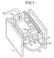
- the magnetometer head shown in FIG. 1 comprises a ceramic plate 101 which serves to support the active organs of the head.
- a smaller wafer 102 cut in a garnet of gadolinium and gallium said GGG whose dimensions length by width and by thickness are about 10 x 3 x 0.7 mm.
- the GGG surface was grown by epitaxy a relatively thick layer of substituted YIG 113 corresponding substantially to the composition Y 2.45 Gd p, 55 Fe 4 . 1 0 12
- the thickness can be obtained between 30 and 110 microns and a typical value is 50 microns.
- Such a thickness of YIG makes it possible to propagate the light in a guided but multimode manner, and under these conditions the Faraday effect due to the magnetic field is manifested only by a rotation of the plane of polarization of the light and no longer by a conversion of the mode TM in TE mode. This makes it possible to couple the light beam by the end faces of the layer of YIG 113.
- the light source is formed by a laser diode 103 fixed on the wafer 101 in such a way that its junction by the edge 104 from which the coherent light beam comes out is located substantially in the center of the layer of YIG.
- the emissive surface of such a diode having substantially a thickness of 0.2 microns and a width of 15 microns, this positioning is relatively easy by playing for example on the layer of adhesive which maintains the laser diode on the wafer 101 or as required. by adding a shim between the diode and the plate.
- This diode is supplied with a suitable electric voltage VE via two input connections.
- a polarizer 105 has been placed which makes it possible to linearly polarize the light emitted by the laser diode in the YIG layer.
- This polarizer is for example cut from a polarizing film of a type commonly used in optics. Its thickness is such that it does not disturb the coupling between the emitting diode and the YIG layer provided that great care is taken to pinch the polarizer moderately between the diode and the wafer 102.
- a groove 106 formed in the wafer 101 makes it possible to facilitate the mounting of the polarizer by immobilizing it, for example with a drop of glue, before positioning the plate 102 and the diode 103.
- an analyzer 107 was placed similar to the polarizer 105 but crossed with respect to it and immobilized for mounting in another slot 108.
- This analyzer is slightly pinched between the plate 102 and a detector photodiode 109.
- This photodiode is for example of the germanium type subjected to a reverse polarization of around ten volts and its active surface is produced in the form of substantially a rectangle for capture the maximum light output from the YIG layer. Under these conditions, it transmits a VS signal.
- the plate 101 and all of the active elements which it supports are placed inside a solenoid 110 which makes it possible to apply the magnetic compensation field and the alternating measurement field.
- the figure clearly shows that the overall dimensions of the measurement head obtained are of the order of the largest dimension of the plate 101, that is to say of about 1 cm.
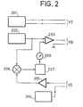
- the measurement head shown in FIG. 1 is connected by a multiconductor cable to the measurement box, the simplified diagram of which is shown in FIG. 2.
- This box firstly comprises a stabilized power source 201 which supplies the current necessary to supply the laser diode 103.
- a stabilized power source 201 which supplies the current necessary to supply the laser diode 103.
- a light power of 4 milli- watts is obtained with an intensity of 200 milliamps.
- Such a light power at this wavelength perfectly makes it possible to operate the device with the desired sensitivity.
- An oscillator 202 provides a relatively high frequency signal, 100 kHz for example. This signal is added to a continuous or slightly variable signal in an amplifier 203 which delivers a voltage VB applied to solenoid 110.
- a bias voltage generator 204 makes it possible to deliver the bias voltage from the diode 109 which, by detecting the light beam, delivers the signal VS.
- This signal VS is amplified in a selective amplifier 205 centered on the frequency of the signal supplied by the oscillator 202.
- the signal at the output of this amplifier 205 is compared with the signal at the output of the oscillator 202 in a synchronous detector 206 which measures both the amplitude of the signal at the fundamental frequency and its phase change during the zero crossing of this amplitude. This detector delivers an error signal.
- This error signal is applied to a servomechanism 207 which includes for example a voltage generator and a correcting filter which make it possible to generate a feedback voltage which, applied via the amplifier 203 to the solenoid 110, tends canceling the error signal at the output of comparator 206 by compensating for the magnetic field to be measured in the interior of the YIG layer 113.
- a servomechanism 207 which includes for example a voltage generator and a correcting filter which make it possible to generate a feedback voltage which, applied via the amplifier 203 to the solenoid 110, tends canceling the error signal at the output of comparator 206 by compensating for the magnetic field to be measured in the interior of the YIG layer 113.
- the value of the compensating magnetic field is measured by means of the value of the signal which generates it and which is applied by the servomechanism 207 to the amplifier 203.
- measure 208 is inserted between the servomechanism 207 and the amplifier 203.
- measuring head whose volume is of the order of cubic centimeter, has a sensitivity of about 10- 7 to Oersted magnetic field may change in a range of frequencies ranging from continuous to 1000 Hertz.
Landscapes
- Engineering & Computer Science (AREA)
- Power Engineering (AREA)
- Physics & Mathematics (AREA)
- Condensed Matter Physics & Semiconductors (AREA)
- General Physics & Mathematics (AREA)
- Measuring Magnetic Variables (AREA)
- Superconductor Devices And Manufacturing Methods Thereof (AREA)
- Investigating Or Analyzing Materials By The Use Of Magnetic Means (AREA)
Applications Claiming Priority (2)
| Application Number | Priority Date | Filing Date | Title |
|---|---|---|---|
| FR7930721 | 1979-12-14 | ||
| FR7930721A FR2471608A1 (fr) | 1979-12-14 | 1979-12-14 | Tete de mesure pour magnetometre, et magnetometre comprenant une telle tete |
Publications (2)
| Publication Number | Publication Date |
|---|---|
| EP0030876A1 EP0030876A1 (fr) | 1981-06-24 |
| EP0030876B1 true EP0030876B1 (fr) | 1983-11-23 |
Family
ID=9232793
Family Applications (1)
| Application Number | Title | Priority Date | Filing Date |
|---|---|---|---|
| EP80401647A Expired EP0030876B1 (fr) | 1979-12-14 | 1980-11-17 | Tête de mesure pour magnétomètre, et son utilisation dans un magnétomètre |
Country Status (7)
| Country | Link |
|---|---|
| US (1) | US4449096A (Direct) |
| EP (1) | EP0030876B1 (Direct) |
| JP (1) | JPS5693062A (Direct) |
| CA (1) | CA1175907A (Direct) |
| DE (1) | DE3065720D1 (Direct) |
| FR (1) | FR2471608A1 (Direct) |
| NO (1) | NO154558C (Direct) |
Families Citing this family (13)
| Publication number | Priority date | Publication date | Assignee | Title |
|---|---|---|---|---|
| FR2517831A2 (fr) * | 1981-12-04 | 1983-06-10 | Thomson Csf | Tete de mesure pour magnetometre et magnetometre comprenant une telle tete |
| FR2548787B1 (fr) * | 1983-07-04 | 1986-01-31 | Thomson Csf | Tete de mesure pour appareil de mesure de vecteur de gradient de champ magnetique, appareil de mesure comprenant une telle tete et procede de mesure |
| FR2552883B1 (fr) * | 1983-10-04 | 1985-11-08 | Thomson Csf | Dispositif pour mesurer le gradient d'un champ magnetique par effet magneto-optique |
| DE3341265A1 (de) * | 1983-11-15 | 1985-05-23 | Phönix Armaturen-Werke Bregel GmbH, 6000 Frankfurt | Messgeraet |
| GB2164145B (en) * | 1984-09-04 | 1989-01-05 | Westinghouse Electric Corp | Temperature compensated current sensor involving faraday effect and fiber optics |
| FR2603705B1 (fr) * | 1986-09-05 | 1988-10-28 | Thomson Csf | Tete de mesure de champ magnetique integree et son procede de realisation |
| US4947107A (en) * | 1988-06-28 | 1990-08-07 | Sundstrand Corporation | Magneto-optic current sensor |
| EP0363914A3 (en) * | 1988-10-13 | 1991-07-31 | Nec Corporation | Optical device with optical polarizer/analyzer formed of yttrium vanadate |
| US4981341A (en) * | 1989-07-14 | 1991-01-01 | At&T Bell Laboratories | Apparatus comprising a magneto-optic isolator utilizing a garnet layer |
| JP2758693B2 (ja) * | 1990-04-18 | 1998-05-28 | 信越化学工業株式会社 | 光アイソレータおよびその製造方法 |
| JPH0476476A (ja) * | 1990-07-19 | 1992-03-11 | Ngk Insulators Ltd | 光磁界センサ |
| US5451863A (en) * | 1992-10-30 | 1995-09-19 | International Business Machines Corporation | Fiber optic probe with a magneto-optic film on an end surface for detecting a current in an integrated circuit |
| US5258869A (en) * | 1992-12-31 | 1993-11-02 | Xerox Corporation | Xerographic laser light modulation with built-in light leveling using optical circulators |
Family Cites Families (4)
| Publication number | Priority date | Publication date | Assignee | Title |
|---|---|---|---|---|
| US3512867A (en) * | 1967-05-18 | 1970-05-19 | Philips Corp | Magneto-optical digital light deflection device |
| US3756690A (en) * | 1972-03-30 | 1973-09-04 | Corning Glass Works | Optical waveguide light modulator |
| DE2452489C2 (de) * | 1974-11-05 | 1984-11-15 | Siemens AG, 1000 Berlin und 8000 München | Nichtreziprokes Bauelement für die integrierte Optik |
| FR2355299A1 (fr) * | 1976-06-18 | 1978-01-13 | Thomson Csf | Appareil destine a mesurer un champ magnetique |
-
1979
- 1979-12-14 FR FR7930721A patent/FR2471608A1/fr active Granted
-
1980
- 1980-11-17 EP EP80401647A patent/EP0030876B1/fr not_active Expired
- 1980-11-17 DE DE8080401647T patent/DE3065720D1/de not_active Expired
- 1980-12-03 US US06/212,620 patent/US4449096A/en not_active Expired - Lifetime
- 1980-12-09 CA CA000366425A patent/CA1175907A/en not_active Expired
- 1980-12-12 NO NO803767A patent/NO154558C/no unknown
- 1980-12-12 JP JP17480780A patent/JPS5693062A/ja active Pending
Also Published As
| Publication number | Publication date |
|---|---|
| FR2471608A1 (fr) | 1981-06-19 |
| NO803767L (no) | 1981-06-15 |
| NO154558B (no) | 1986-07-07 |
| NO154558C (no) | 1986-10-15 |
| US4449096A (en) | 1984-05-15 |
| JPS5693062A (en) | 1981-07-28 |
| DE3065720D1 (en) | 1983-12-29 |
| CA1175907A (en) | 1984-10-09 |
| FR2471608B1 (Direct) | 1982-08-13 |
| EP0030876A1 (fr) | 1981-06-24 |
Similar Documents
| Publication | Publication Date | Title |
|---|---|---|
| EP0081412B1 (fr) | Tête de mesure pour magnétomètre | |
| EP0030876B1 (fr) | Tête de mesure pour magnétomètre, et son utilisation dans un magnétomètre | |
| EP0091351B1 (fr) | Magnétomètre optique | |
| EP2795354B1 (fr) | Magnétomètre à pompage optique intégré et isotrope | |
| EP3454139B1 (fr) | Système de mesure optique à asservissement davll stabilisé et procédé associé | |
| EP0462002A1 (fr) | Magnétomètre à résonance et à pompage optique utilisant une polarisation séquentielle | |
| EP0246146B1 (fr) | Magnétomètre à hélium pompé par laser | |
| EP0130901B1 (fr) | Tête de mesure pour appareil de mesure de vecteur de gradient de champ magnétique, appareil de mesure comprenant une telle tête, et procédé de mesure | |
| EP0656545B1 (fr) | Magnétomètre à polarisation lumineuse et à champ de radiofréquence couplés | |
| EP0461999B1 (fr) | Magnétomètre à résonance et à pompage optique utilisant un faisceau lumineux à polarisation asservie | |
| EP0136955B1 (fr) | Dispositif pour mesurer le gradient d'un champ magnétique par effet magnéto-optique | |
| EP0252813A1 (fr) | Dispositif modulateur haute fréquence de polarisation de la lumière | |
| FR2558963A1 (fr) | Procede de mesure magneto-optique de champs magnetiques, systeme de mesure et tete de mesure utilisant un tel procede | |
| EP3961236B1 (fr) | Magnetometre en polarisation elliptique avec deux composantes de champ radiofrequence pour detection de resonance parametrique en absorption | |
| FR3121560A1 (fr) | Méthode d’asservissement d’un dispositif optique comprenant un laser et une cavité permettant de compenser une modulation d’amplitude introduite par un modulateur de phase | |
| EP3702797A1 (fr) | Magnétomètre scalaire isotrope et tout optique | |
| FR2786888A1 (fr) | Dispositif de modulation de lumiere et dispositif de filtrage | |
| Suzuki et al. | A New Measurement System of the Surface Magneto-Optic Kerr Effect (SMOKE) |
Legal Events
| Date | Code | Title | Description |
|---|---|---|---|
| PUAI | Public reference made under article 153(3) epc to a published international application that has entered the european phase |
Free format text: ORIGINAL CODE: 0009012 |
|
| AK | Designated contracting states |
Designated state(s): DE GB IT NL |
|
| 17P | Request for examination filed |
Effective date: 19810810 |
|
| ITF | It: translation for a ep patent filed | ||
| GRAA | (expected) grant |
Free format text: ORIGINAL CODE: 0009210 |
|
| AK | Designated contracting states |
Designated state(s): DE GB IT NL |
|
| REF | Corresponds to: |
Ref document number: 3065720 Country of ref document: DE Date of ref document: 19831229 |
|
| PLBE | No opposition filed within time limit |
Free format text: ORIGINAL CODE: 0009261 |
|
| STAA | Information on the status of an ep patent application or granted ep patent |
Free format text: STATUS: NO OPPOSITION FILED WITHIN TIME LIMIT |
|
| PGFP | Annual fee paid to national office [announced via postgrant information from national office to epo] |
Ref country code: DE Payment date: 19841022 Year of fee payment: 5 |
|
| 26N | No opposition filed | ||
| PGFP | Annual fee paid to national office [announced via postgrant information from national office to epo] |
Ref country code: NL Payment date: 19871130 Year of fee payment: 8 |
|
| PG25 | Lapsed in a contracting state [announced via postgrant information from national office to epo] |
Ref country code: GB Effective date: 19891117 |
|
| PG25 | Lapsed in a contracting state [announced via postgrant information from national office to epo] |
Ref country code: NL Effective date: 19900601 |
|
| GBPC | Gb: european patent ceased through non-payment of renewal fee | ||
| NLV4 | Nl: lapsed or anulled due to non-payment of the annual fee | ||
| PG25 | Lapsed in a contracting state [announced via postgrant information from national office to epo] |
Ref country code: DE Effective date: 19900801 |