EP0030636B1 - Screw compressor-expander cryogenic system with magnetic coupling - Google Patents
Screw compressor-expander cryogenic system with magnetic coupling Download PDFInfo
- Publication number
- EP0030636B1 EP0030636B1 EP80107184A EP80107184A EP0030636B1 EP 0030636 B1 EP0030636 B1 EP 0030636B1 EP 80107184 A EP80107184 A EP 80107184A EP 80107184 A EP80107184 A EP 80107184A EP 0030636 B1 EP0030636 B1 EP 0030636B1
- Authority
- EP
- European Patent Office
- Prior art keywords
- expander
- compressor
- chamber
- bearings
- rotors
- Prior art date
- Legal status (The legal status is an assumption and is not a legal conclusion. Google has not performed a legal analysis and makes no representation as to the accuracy of the status listed.)
- Expired
Links
- 230000008878 coupling Effects 0.000 title claims description 18
- 238000010168 coupling process Methods 0.000 title claims description 18
- 238000005859 coupling reaction Methods 0.000 title claims description 18
- 238000005461 lubrication Methods 0.000 claims description 22
- 239000003595 mist Substances 0.000 claims description 15
- 239000000314 lubricant Substances 0.000 claims description 14
- 238000005057 refrigeration Methods 0.000 claims description 11
- 239000012530 fluid Substances 0.000 claims description 7
- 230000006835 compression Effects 0.000 claims description 4
- 238000007906 compression Methods 0.000 claims description 4
- 239000007789 gas Substances 0.000 description 44
- 239000003507 refrigerant Substances 0.000 description 9
- 238000000926 separation method Methods 0.000 description 4
- 239000002826 coolant Substances 0.000 description 3
- XKRFYHLGVUSROY-UHFFFAOYSA-N Argon Chemical compound [Ar] XKRFYHLGVUSROY-UHFFFAOYSA-N 0.000 description 2
- IJGRMHOSHXDMSA-UHFFFAOYSA-N Atomic nitrogen Chemical compound N#N IJGRMHOSHXDMSA-UHFFFAOYSA-N 0.000 description 2
- CURLTUGMZLYLDI-UHFFFAOYSA-N Carbon dioxide Chemical compound O=C=O CURLTUGMZLYLDI-UHFFFAOYSA-N 0.000 description 2
- 238000010586 diagram Methods 0.000 description 2
- 238000012856 packing Methods 0.000 description 2
- 238000007789 sealing Methods 0.000 description 2
- UFHFLCQGNIYNRP-UHFFFAOYSA-N Hydrogen Chemical compound [H][H] UFHFLCQGNIYNRP-UHFFFAOYSA-N 0.000 description 1
- 229910052786 argon Inorganic materials 0.000 description 1
- 239000001569 carbon dioxide Substances 0.000 description 1
- 229910002092 carbon dioxide Inorganic materials 0.000 description 1
- 230000000694 effects Effects 0.000 description 1
- 239000001307 helium Substances 0.000 description 1
- 229910052734 helium Inorganic materials 0.000 description 1
- SWQJXJOGLNCZEY-UHFFFAOYSA-N helium atom Chemical compound [He] SWQJXJOGLNCZEY-UHFFFAOYSA-N 0.000 description 1
- 239000001257 hydrogen Substances 0.000 description 1
- 229910052739 hydrogen Inorganic materials 0.000 description 1
- 238000002955 isolation Methods 0.000 description 1
- 230000013011 mating Effects 0.000 description 1
- 239000000203 mixture Substances 0.000 description 1
- 229910052754 neon Inorganic materials 0.000 description 1
- GKAOGPIIYCISHV-UHFFFAOYSA-N neon atom Chemical compound [Ne] GKAOGPIIYCISHV-UHFFFAOYSA-N 0.000 description 1
- 229910052757 nitrogen Inorganic materials 0.000 description 1
- 238000005192 partition Methods 0.000 description 1
- 238000009428 plumbing Methods 0.000 description 1
- 231100000572 poisoning Toxicity 0.000 description 1
- 230000000607 poisoning effect Effects 0.000 description 1
- 239000000725 suspension Substances 0.000 description 1
Images


Classifications
-
- H—ELECTRICITY
- H02—GENERATION; CONVERSION OR DISTRIBUTION OF ELECTRIC POWER
- H02K—DYNAMO-ELECTRIC MACHINES
- H02K49/00—Dynamo-electric clutches; Dynamo-electric brakes
- H02K49/10—Dynamo-electric clutches; Dynamo-electric brakes of the permanent-magnet type
- H02K49/104—Magnetic couplings consisting of only two coaxial rotary elements, i.e. the driving element and the driven element
- H02K49/108—Magnetic couplings consisting of only two coaxial rotary elements, i.e. the driving element and the driven element with an axial air gap
-
- F—MECHANICAL ENGINEERING; LIGHTING; HEATING; WEAPONS; BLASTING
- F04—POSITIVE - DISPLACEMENT MACHINES FOR LIQUIDS; PUMPS FOR LIQUIDS OR ELASTIC FLUIDS
- F04C—ROTARY-PISTON, OR OSCILLATING-PISTON, POSITIVE-DISPLACEMENT MACHINES FOR LIQUIDS; ROTARY-PISTON, OR OSCILLATING-PISTON, POSITIVE-DISPLACEMENT PUMPS
- F04C23/00—Combinations of two or more pumps, each being of rotary-piston or oscillating-piston type, specially adapted for elastic fluids; Pumping installations specially adapted for elastic fluids; Multi-stage pumps specially adapted for elastic fluids
- F04C23/001—Combinations of two or more pumps, each being of rotary-piston or oscillating-piston type, specially adapted for elastic fluids; Pumping installations specially adapted for elastic fluids; Multi-stage pumps specially adapted for elastic fluids of similar working principle
- F04C23/003—Combinations of two or more pumps, each being of rotary-piston or oscillating-piston type, specially adapted for elastic fluids; Pumping installations specially adapted for elastic fluids; Multi-stage pumps specially adapted for elastic fluids of similar working principle having complementary function
-
- F—MECHANICAL ENGINEERING; LIGHTING; HEATING; WEAPONS; BLASTING
- F04—POSITIVE - DISPLACEMENT MACHINES FOR LIQUIDS; PUMPS FOR LIQUIDS OR ELASTIC FLUIDS
- F04C—ROTARY-PISTON, OR OSCILLATING-PISTON, POSITIVE-DISPLACEMENT MACHINES FOR LIQUIDS; ROTARY-PISTON, OR OSCILLATING-PISTON, POSITIVE-DISPLACEMENT PUMPS
- F04C27/00—Sealing arrangements in rotary-piston pumps specially adapted for elastic fluids
- F04C27/008—Sealing arrangements in rotary-piston pumps specially adapted for elastic fluids for other than working fluid, i.e. the sealing arrangements are not between working chambers of the machine
- F04C27/009—Shaft sealings specially adapted for pumps
-
- F—MECHANICAL ENGINEERING; LIGHTING; HEATING; WEAPONS; BLASTING
- F04—POSITIVE - DISPLACEMENT MACHINES FOR LIQUIDS; PUMPS FOR LIQUIDS OR ELASTIC FLUIDS
- F04C—ROTARY-PISTON, OR OSCILLATING-PISTON, POSITIVE-DISPLACEMENT MACHINES FOR LIQUIDS; ROTARY-PISTON, OR OSCILLATING-PISTON, POSITIVE-DISPLACEMENT PUMPS
- F04C29/00—Component parts, details or accessories of pumps or pumping installations, not provided for in groups F04C18/00 - F04C28/00
- F04C29/0042—Driving elements, brakes, couplings, transmissions specially adapted for pumps
- F04C29/005—Means for transmitting movement from the prime mover to driven parts of the pump, e.g. clutches, couplings, transmissions
- F04C29/0064—Magnetic couplings
-
- F—MECHANICAL ENGINEERING; LIGHTING; HEATING; WEAPONS; BLASTING
- F25—REFRIGERATION OR COOLING; COMBINED HEATING AND REFRIGERATION SYSTEMS; HEAT PUMP SYSTEMS; MANUFACTURE OR STORAGE OF ICE; LIQUEFACTION SOLIDIFICATION OF GASES
- F25B—REFRIGERATION MACHINES, PLANTS OR SYSTEMS; COMBINED HEATING AND REFRIGERATION SYSTEMS; HEAT PUMP SYSTEMS
- F25B1/00—Compression machines, plants or systems with non-reversible cycle
- F25B1/04—Compression machines, plants or systems with non-reversible cycle with compressor of rotary type
- F25B1/047—Compression machines, plants or systems with non-reversible cycle with compressor of rotary type of screw type
-
- F—MECHANICAL ENGINEERING; LIGHTING; HEATING; WEAPONS; BLASTING
- F25—REFRIGERATION OR COOLING; COMBINED HEATING AND REFRIGERATION SYSTEMS; HEAT PUMP SYSTEMS; MANUFACTURE OR STORAGE OF ICE; LIQUEFACTION SOLIDIFICATION OF GASES
- F25B—REFRIGERATION MACHINES, PLANTS OR SYSTEMS; COMBINED HEATING AND REFRIGERATION SYSTEMS; HEAT PUMP SYSTEMS
- F25B9/00—Compression machines, plants or systems, in which the refrigerant is air or other gas of low boiling point
- F25B9/06—Compression machines, plants or systems, in which the refrigerant is air or other gas of low boiling point using expanders
-
- F—MECHANICAL ENGINEERING; LIGHTING; HEATING; WEAPONS; BLASTING
- F25—REFRIGERATION OR COOLING; COMBINED HEATING AND REFRIGERATION SYSTEMS; HEAT PUMP SYSTEMS; MANUFACTURE OR STORAGE OF ICE; LIQUEFACTION SOLIDIFICATION OF GASES
- F25B—REFRIGERATION MACHINES, PLANTS OR SYSTEMS; COMBINED HEATING AND REFRIGERATION SYSTEMS; HEAT PUMP SYSTEMS
- F25B2309/00—Gas cycle refrigeration machines
- F25B2309/06—Compression machines, plants or systems characterised by the refrigerant being carbon dioxide
-
- H—ELECTRICITY
- H02—GENERATION; CONVERSION OR DISTRIBUTION OF ELECTRIC POWER
- H02K—DYNAMO-ELECTRIC MACHINES
- H02K5/00—Casings; Enclosures; Supports
- H02K5/04—Casings or enclosures characterised by the shape, form or construction thereof
- H02K5/12—Casings or enclosures characterised by the shape, form or construction thereof specially adapted for operating in liquid or gas
- H02K5/128—Casings or enclosures characterised by the shape, form or construction thereof specially adapted for operating in liquid or gas using air-gap sleeves or air-gap discs
Definitions
- This invention is directed to a refrigerator system comprising a compressor housing having a compressor chamber therein, first and second interengaging rotors in said compressor chamber arranged in bearings so that rotation of said rotors causes gas compression in said compressor chamber; motor means connected to said first compressor rotor for driving said first compressor rotor; an expander housing having an expander chamber therein, first and second interengaging rotors in said expander chamber arranged in bearings so that rotation of said rotors causes gas expansion in said expander chamber to produce refrigeration; means for rotationally coupling one of said compressor rotors to one.
- a refrigeration system of this kind is disclosed in EP-A-0 004 609.
- the shaft of the driven compressor rotor is mounted coaxially to the shaft of one- of the expander rotors and coupled thereto by means of a spline connection:
- the spline connection is arranged in a separate chamber positioned between the compressor chamber and the expander chamber, and separated therefrom by sealings which are arranged adjacent to bearings. in which the said shafts are rotatably mounted.
- the said bearings are positioned in walls separating said intermediate chamber from the said compressor chamber and the said expander chamber, respectively.
- CH-A-469 235 and GB-A-2 021 32.7 describe magnetic couplings in refrigerator systems between an expander turbine and a rotational machine coupled to the turbine, wherein the fluid circuit of the expander turbine is completely separated from the rotational machine, and between the motor and the compressor of a refrigerator system, wherein also a complete separation is provided between the motor and the compressor, respectively.
- the magnetic coupling is arranged between two different devices which are generally produced as separate units and may be separately included in various arrangments.
- US-A-3 299 655 and DE-C-352579 disclose lubricant circulation loops connected to the bearings of a refrigerator system, in order to deliver oil as lubricant under high pressure into the bearings.
- the machine disclosed in DE-C-352 579 has a plurality of bearings and a separate loop is provided for each bearing.
- an oil and gas mixture exists in the return branch thereof, and means for separating the oil from the gas is provided therein.
- a wall is arranged between said compressor chamber and said expander chamber, and the said coupling means comprises first magnetic means positioned on one side of said wall and connected to rotate with one of said compressor rotors, and second magnetic means positioned on the other side of said wall and magnetically coupled with said first magnetic means and connected to rotate with one of said expander rotors, and that first and second closed lubricant circulation loops are provided, each lubricant loop having a blower therein for circulating an oil mist and gas lubrication fluid to those of said bearings which are connected to the respective loop, the first lubrication loop being connected to said bearings adjacent the ends of said chambers at said first pressure, and the second lubrication loop being connected to said bearings adjacent the ends of said chambers at said second pressure.
- the invention provides for a complete separation between the compressor and expander chambers of a closed loop refrigerator system, besides the interconnection of these chambers provided by the refrigerator gas loop.
- this separation does not provide an isolation of the two chambers from each other, but eliminates any pressure drop along the bearings of the rotors mounted therein.
- the interconnection of the chambers by means of the refrigerator gas loop results in that a pluarlity of bearings has the same pressure, so that such bearings may be included in the same lubrication loop.
- only two different lubrication loops are needed, in which an oil mist may be circulated in order to provide an improved lubrication of the bearings and a perfect separation of the lubricant from the refrigerator gas.
- the invention provides for a long-life, trouble-free cyrogenic refrigerator, in which gas leakage through the rotor bearings is minimized and increased refrigeration per units of weight and input power is achieved.
- the mechanical equipment 10 of the screw compressor-expander cyrogenic system is generally indicated in FIGS. 1, 2 and 3. In FIG. 1 it is shown in association with the external gas. flow equipment 12 which completes. the cyrogenic system and in FIG. 2 it is shown in association with the lubrication plumbing 14- which is external to the machinery 10..
- the machinery 10 comprises drive motor 16 which is usually an electric motor and is positioned within motor housing 18. Motor housing 18 is divided by wall 20 so that the motor bearings 22 and 24 in bearing bosses 26 and 28. are in separate lubrication compartments.
- End wall 30 serves as the end wall for compressor chamber 32 as well as a mounting boss for the compressor drive end bearings 34 and 36.
- Wall 38 through motor housing 18 separates the compressor drive end bearings 34 and 36 from motor drive end bearing 24 to provide separate compartments for these bearings.
- compressor chamber 32 The other end of compressor chamber 32 is closed by end wall 39 which carries back end compressor bearings 40 and 42.
- Magnetic coupling compartment 44. is separated from magnetic coupling compartment 46 by thin magnetic wall 48.
- Magnetic coupling disc 50 is mounted. on the end of the compressor shaft to rotate therewith.
- the compressor shaft is coupled to the motor shaft so that the whole structure is driven by the motor.
- Magnetic coupling disc 52 faces disc 50 from compartment 46 so that magnetic coupling between the discs takes place through wall 48.
- Each of the discs is a multiple magnet arranged so that the magnets can couple together to transmit torque.
- Disc 52 is mounted on expander shaft 54 which extends out of expander compartment 56 on low thermal loss hollow shafts.
- the companion expander shaft 58 carries the mating expander rotor.
- the expander shafts are carried on bearings 60 and 62. in compartment 46 while the bearings 64-and 66 carry the other ends of the expander shafts in compartment 68.
- Each of the bearings is provided with a seal between the bearing and the adjacent compressor or expander chamber.
- the rotors are designed such that the gas dynamics in the space between the rotors holds them apart so that no timing gears are necessary to prevent machanicai contact between the rotors.
- an expander 70 expanding air from one atmosphere to 0.5 atmosphere while running at 10,000 rpm can operate without contact. In a test of that nature, the rotors were inspected after a one hour test andshowed no contact or- wear.
- compressor 72 receives refrigerant gas at its right end through suction line 74 and compresses it within chamber 32 to deliver it in pressure line 76.
- suitable pressures are respectively 0.5 atmospheres in the suction line 74 and. one atmosphere in the pressure line 76.
- Suitabie refrigerant gases depend on the desired temperature, but include nitrogen, argon, carbon dioxide; neon, helium and hydrogen. The gas selected and the line pressures depend on the desired end temperature.
- Jacket 78 carries a coolant which carries off some of the heat of compression while after cooler 80 brings the refrigerant fluid in the pressure line 76 almost down to the temperature of the coolant in coolant line 82.
- Counterflow heat-exchanger 84 further cools the gas flowing in pressure line 76. From heat exchanger 84, the gas in pressure line 76 goes into the expander chamber 56 at the left end which is the high pressure end of expander 70. Rotation of the rotors in the expander chamber expand the gas into cold line 86 which is at the pressure of suction line 74. Heat load 88 adds heat to the gas while the heat load 88 is cooled. From the heat load 88 the- gas passes through counter flow heat exchanger 84 and back to the suction line 74 of compressor 72.
- One of the specific improvements is the fact that there is a wall 48 between the compressor and expander, with power transferred between the compressor and expander through the magnetic coupling. Because of the partition wall and the magnetic coupling there is no flow of gas between the compressor housing and the expander housing and thus the pressur in the adjacent bearing compartment is equal to the adjacent gas pressure in the chamber in the housing. In other words, there is no pressure drop which would drive lubricant from the bearing into the compressor or expander chamber or which would drive refrigerant gas into the bearings to drive lubricant out of the bearings.
- Radial blower 90 see FIG. 2 draws gas from compartment 68 together with the oil suspended in the gas and discharges it out line 92 where it is passed to compartment 44, see FIG. 3. From the- top of compartment 44, line 94, carries the oil mist suspended in refrigerant gas back through compartment 68 to blower 90.
- the blower 90 maintains the oil in mist suspension as it passes through the lines and bearing compartments so that the bearings are continuously lubricated.
- the bearings 40, 42, 64- and 66 are lubricated by this circuit From FIG.
- Lubricant blower 96 is driven by the idler rotor in compressor 72. It draws refrigerant gas and suspended oil mist from the compartment of bearings. 34 and 36 and delivers it through line 97 of compartment 46 where it serves to lubricate bearings 60 and 62. From that compartment, the mist is conveyed through line 98 to lubricate the bearing 22 and thence through line 100 to lubricate the: other motor bearing 24. From thence; line 102 conveys the mist back to the compartment adjacent bearings 34. and 36 from whence it is drawn back into the blower 96 to continue its continuous closed cycle. The continuous closed cycle from blower 96 distributes lubricant through bearing compartments which are at the same- pressure as the adjacent gas of in this case 1 atmosphere so there is no differential pressure across the bearings from adjacent compartments. This reduces load on- the bearing seals.
- FIG. 4 Another preferred embodiment of the screw compressor-expander cyrogenic system of this invention is generally indicated at 104 in FIG. 4. It comprises a motor 106 (Fig. 7) which drives compressor 108 which has rotors 110 and 112 of the type previously described.
- the rotor 110 is driven directly by motor 106 and rotor 112 is preferably driven by gas film between the lobes and recesses on the rotors so that no mechanical contact takes place.
- the bearings of the motor, compressor and the expanders are lubricated by a circulating mist as described above.
- Magnetic coupling plates 114 and 116 operate through thin wall 118 so that power is interchanged between compressor 108 and expander 120.
- Expander 120 has rotors 122 and 124 which are preferably separated by the hydrodynamic gas film. Expander 120 is coupled to expander 126 by means of magnetic coupling plates 128 and 130 which operate through wall 132. Expander rotors 134 and 136 expand gas: in the chambers defined by the lobes and recesses on the rotors and again the rotor 136 is preferably separated from rotor 134 by a hydrodynamic gas film so that no mechanical connection is necessary.
- All bearings are lubricated by mist lubrication in order to provide a long life, and the mist lubrication circuits are defined in such a manner that bearings at the same pressure are connected together on the same mist lubrication circuit and the bearings at different pressure are on separate mist lubrication circuits.
- valve structure 140 is illustrative of valve structures 142 and 144 which are of similar design, with the details of valve structure 140 illustrated in FIGS. 5 and 6.
- Valve disc 146 is rotated by shaft 148 which is the shaft of rotor 124. Openings 150 and 152 are formed through disc 146 and are illustrated as being approximately half circular. They are positioned to cover and uncover valve ports 154 and 156 respectively.
- valve ports 154 and 156 When cyrogenic gas under pressure is provided in chamber 158 then the gas is alternately ported to the lines connected to valve ports 154 and 156.
- the configuration of openings 150 and 152 depends on the gas, the rotative speed and the pressure, and the ports may be overlapped or underiapped depending on particular conditions. As illustrated in FIG. 6, they are slightly underiapped.
- the ports 154 and 156 with their corresponding openings are in effect separate valves which open at approximately opposite times.
- the valving is separately shown.
- Similar valve ports 162 and 164 are shown in connection with compressor 108 and valve ports 166 and 168 are shown in connection with expander 126. As the compressor and expanders rotate the valves open and close to reverse flow in much of the system.
- FIG. 7 flow arrows are shown in connection with one position of the valving, and it is understood that with a half turn of the valve discs, some of the flows are reversed. The direction of flow and the reversing flow will be discussed in connection with the following description of. the schematic of FIG. 7 of the ssytem.
- the flow arrows shown in FIG. 7 are for one portion of the flow cycle.
- the valves are alternately operable so that flow direction through the regenerators reverses from time to time.
- compressor 108 takes suction of refrigerant gas, compresses the gas and delivers it through heat exchanger 170 where heat is rejected to the ambiment.
- regenerator 172 Another portion of the downflowing cyrogenic refrigerator gas stream in regenerator 172 is taken out of the regenerator at line 182 where it passes- into the. high pressure end of the second stage expander 126. After it is expanded therein it passes out through valve 168 and then through load heat exchanger 184 which is at about 40°K. From load heat exchanger the cyrogenic refrigerant gas is delivered to the bottom of regenerator 176 and it is moved upwardly therethrough joining the stream from load heat exchanger 180 to absorb heat from the regenerator packing. At the top of the regenerator the cyrogenic fluid passes through line 186 and back to the suction of compressor 108.
- valves 162, 156 and 168 close: while the 7 valves 164, 154 and 166 open to reverse the flow through the regenerators.
Landscapes
- Engineering & Computer Science (AREA)
- Mechanical Engineering (AREA)
- General Engineering & Computer Science (AREA)
- Physics & Mathematics (AREA)
- Thermal Sciences (AREA)
- Power Engineering (AREA)
- Applications Or Details Of Rotary Compressors (AREA)
Description
- This invention is directed to a refrigerator system comprising a compressor housing having a compressor chamber therein, first and second interengaging rotors in said compressor chamber arranged in bearings so that rotation of said rotors causes gas compression in said compressor chamber; motor means connected to said first compressor rotor for driving said first compressor rotor; an expander housing having an expander chamber therein, first and second interengaging rotors in said expander chamber arranged in bearings so that rotation of said rotors causes gas expansion in said expander chamber to produce refrigeration; means for rotationally coupling one of said compressor rotors to one. of said expander rotors for transmitting power between said compressor rotor and expander rotor and for controlling the speed of said expander rotor; means interconnecting between said compressor chamber and said expander chamber and between a heat load and means for rejecting heat for providing refrigeration to said heat load, wherein one of said ends of said compressor is at a first pressure and the other end of said compressor is at a second pressure, and one of said ends of said expander is substantially at said first pressure and the other end of said expander is substantially at said second pressure.
- A refrigeration system of this kind is disclosed in EP-A-0 004 609. In this known refrigerator system, the shaft of the driven compressor rotor is mounted coaxially to the shaft of one- of the expander rotors and coupled thereto by means of a spline connection: The spline connection is arranged in a separate chamber positioned between the compressor chamber and the expander chamber, and separated therefrom by sealings which are arranged adjacent to bearings. in which the said shafts are rotatably mounted. The said bearings are positioned in walls separating said intermediate chamber from the said compressor chamber and the said expander chamber, respectively. In this known system, there is a heavy pressure drop along the bearings, which despite the provided sealings may drive gas into and lubricant out of the bearings. Thus, there is a danger of failure becasue of insufficient lubrication of the bearings, and because of poisoning the refrigeration gas with lubricant.
- CH-A-469 235 and GB-A-2 021 32.7 describe magnetic couplings in refrigerator systems between an expander turbine and a rotational machine coupled to the turbine, wherein the fluid circuit of the expander turbine is completely separated from the rotational machine, and between the motor and the compressor of a refrigerator system, wherein also a complete separation is provided between the motor and the compressor, respectively. In both cases, the magnetic coupling is arranged between two different devices which are generally produced as separate units and may be separately included in various arrangments.
- US-A-3 299 655 and DE-C-352579 disclose lubricant circulation loops connected to the bearings of a refrigerator system, in order to deliver oil as lubricant under high pressure into the bearings. The machine disclosed in DE-C-352 579 has a plurality of bearings and a separate loop is provided for each bearing. In the lubircation loop disclosed in US-A-3 299 655 an oil and gas mixture exists in the return branch thereof, and means for separating the oil from the gas is provided therein.
- It is the object of the invention to improve the . specified refrigerator system in such a way that the danger of driving lubricant from the bearings into the compressor or expander chamber is obviated and the lubrication of the bearings is improved.
- This object is met by the invention which is characterized in that a wall is arranged between said compressor chamber and said expander chamber, and the said coupling means comprises first magnetic means positioned on one side of said wall and connected to rotate with one of said compressor rotors, and second magnetic means positioned on the other side of said wall and magnetically coupled with said first magnetic means and connected to rotate with one of said expander rotors, and that first and second closed lubricant circulation loops are provided, each lubricant loop having a blower therein for circulating an oil mist and gas lubrication fluid to those of said bearings which are connected to the respective loop, the first lubrication loop being connected to said bearings adjacent the ends of said chambers at said first pressure, and the second lubrication loop being connected to said bearings adjacent the ends of said chambers at said second pressure.
- In contrast to the prior art, the invention provides for a complete separation between the compressor and expander chambers of a closed loop refrigerator system, besides the interconnection of these chambers provided by the refrigerator gas loop. Thus, this separation does not provide an isolation of the two chambers from each other, but eliminates any pressure drop along the bearings of the rotors mounted therein. Further, the interconnection of the chambers by means of the refrigerator gas loop results in that a pluarlity of bearings has the same pressure, so that such bearings may be included in the same lubrication loop. Thus, only two different lubrication loops are needed, in which an oil mist may be circulated in order to provide an improved lubrication of the bearings and a perfect separation of the lubricant from the refrigerator gas. The invention provides for a long-life, trouble-free cyrogenic refrigerator, in which gas leakage through the rotor bearings is minimized and increased refrigeration per units of weight and input power is achieved.
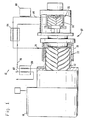
- Fig. 1 is a side elevational view of a compressor expander system of this invention.
- Fig. 2 is a side elevational view of a similar screw compressor-expander cryogenic system showing the machinery as interconnected by a lubrication system.
- FIG. 3 is a longitudinal section taken through the center line of a screw compressor-expander cyrogenic system showing the details of the compression and the expansion chambers, the magnetic coupling transmitting power and speed control between the compressor and the expander rotors and the lubrication of the various bearings.
- FIG. 4 is a longitudinal section through another preferred embodiment of the screw compressor-expander cryogenic system of this- invention with magnetic coupling between the stages, with multiple expander stages and with valving for reversing flow in external passages so that it can be used in conjunction with heat exchange regenerators.
- FIG. 5 is a longitudinal section through a valve suitable for flow reversing.
- FIG. 6 is an elevational view of the valve face, as seen generally along the line 6-6 of FIG. 5.
- FIG. 7 is a schematic flow diagram showing the screw compressor-expander cryogenic system of FIG. 4- with two expander stages and with heat exchange regnerators.
- The
mechanical equipment 10 of the screw compressor-expander cyrogenic system is generally indicated in FIGS. 1, 2 and 3. In FIG. 1 it is shown in association with the external gas.flow equipment 12 which completes. the cyrogenic system and in FIG. 2 it is shown in association with the lubrication plumbing 14- which is external to themachinery 10.. Themachinery 10 comprisesdrive motor 16 which is usually an electric motor and is positioned withinmotor housing 18.Motor housing 18 is divided bywall 20 so that themotor bearings bearing bosses -
End wall 30 serves as the end wall forcompressor chamber 32 as well as a mounting boss for the compressordrive end bearings Wall 38 throughmotor housing 18 separates the compressordrive end bearings - The other end of
compressor chamber 32 is closed byend wall 39 which carries backend compressor bearings 40 and 42. Magnetic coupling compartment 44. is separated frommagnetic coupling compartment 46 by thinmagnetic wall 48.Magnetic coupling disc 50 is mounted. on the end of the compressor shaft to rotate therewith. - As it is seen in FIG. 3, the compressor shaft is coupled to the motor shaft so that the whole structure is driven by the motor.
Magnetic coupling disc 52 facesdisc 50 fromcompartment 46 so that magnetic coupling between the discs takes place throughwall 48. Each of the discs is a multiple magnet arranged so that the magnets can couple together to transmit torque.Disc 52 is mounted onexpander shaft 54 which extends out ofexpander compartment 56 on low thermal loss hollow shafts. The companion expander shaft 58 carries the mating expander rotor. The expander shafts are carried onbearings compartment 46 while the bearings 64-and 66 carry the other ends of the expander shafts incompartment 68. Each of the bearings is provided with a seal between the bearing and the adjacent compressor or expander chamber. - The rotors are designed such that the gas dynamics in the space between the rotors holds them apart so that no timing gears are necessary to prevent machanicai contact between the rotors. By appropriate rotor design, an expander 70 expanding air from one atmosphere to 0.5 atmosphere while running at 10,000 rpm can operate without contact. In a test of that nature, the rotors were inspected after a one hour test andshowed no contact or- wear.
- As seen in FIG. 1,
compressor 72 receives refrigerant gas at its right end throughsuction line 74 and compresses it withinchamber 32 to deliver it inpressure line 76. As indicated above suitable pressures are respectively 0.5 atmospheres in thesuction line 74 and. one atmosphere in thepressure line 76. Suitabie refrigerant gases depend on the desired temperature, but include nitrogen, argon, carbon dioxide; neon, helium and hydrogen. The gas selected and the line pressures depend on the desired end temperature.Jacket 78 carries a coolant which carries off some of the heat of compression while aftercooler 80 brings the refrigerant fluid in thepressure line 76 almost down to the temperature of the coolant incoolant line 82. Counterflow heat-exchanger 84 further cools the gas flowing inpressure line 76. Fromheat exchanger 84, the gas inpressure line 76 goes into theexpander chamber 56 at the left end which is the high pressure end of expander 70. Rotation of the rotors in the expander chamber expand the gas intocold line 86 which is at the pressure ofsuction line 74.Heat load 88 adds heat to the gas while theheat load 88 is cooled. From theheat load 88 the- gas passes through counterflow heat exchanger 84 and back to thesuction line 74 ofcompressor 72. - One of the specific improvements is the fact that there is a
wall 48 between the compressor and expander, with power transferred between the compressor and expander through the magnetic coupling. Because of the partition wall and the magnetic coupling there is no flow of gas between the compressor housing and the expander housing and thus the pressur in the adjacent bearing compartment is equal to the adjacent gas pressure in the chamber in the housing. In other words, there is no pressure drop which would drive lubricant from the bearing into the compressor or expander chamber or which would drive refrigerant gas into the bearings to drive lubricant out of the bearings. - In order to aid in bearing lubrication oil mist lubrication is provided.
Radial blower 90, see FIG. 2 draws gas fromcompartment 68 together with the oil suspended in the gas and discharges it outline 92 where it is passed to compartment 44, see FIG. 3. From the- top of compartment 44,line 94, carries the oil mist suspended in refrigerant gas back throughcompartment 68 toblower 90. When there is an oil mist of 1 to 5% per volume of bearing lubrication oil to refrigerant gas, theblower 90 maintains the oil in mist suspension as it passes through the lines and bearing compartments so that the bearings are continuously lubricated. Thebearings 40, 42, 64- and 66 are lubricated by this circuit From FIG. 1, it can be seen that the ends of the- corresponding compressor and expander chambers adjacent these bearings are at the same pressure, the pressure oflow pressure line 74 so that there is no pressure drop between the bearing compartment and the chambers so that the oil is not driven one- way or another. -
Lubricant blower 96 is driven by the idler rotor incompressor 72. It draws refrigerant gas and suspended oil mist from the compartment of bearings. 34 and 36 and delivers it throughline 97 ofcompartment 46 where it serves to lubricatebearings line 98 to lubricate thebearing 22 and thence throughline 100 to lubricate the:other motor bearing 24. From thence;line 102 conveys the mist back to the compartmentadjacent bearings 34. and 36 from whence it is drawn back into theblower 96 to continue its continuous closed cycle. The continuous closed cycle fromblower 96 distributes lubricant through bearing compartments which are at the same- pressure as the adjacent gas of in this case 1 atmosphere so there is no differential pressure across the bearings from adjacent compartments. This reduces load on- the bearing seals. - Another preferred embodiment of the screw compressor-expander cyrogenic system of this invention is generally indicated at 104 in FIG. 4. It comprises a motor 106 (Fig. 7) which drives
compressor 108 which hasrotors rotor 110 is driven directly bymotor 106 androtor 112 is preferably driven by gas film between the lobes and recesses on the rotors so that no mechanical contact takes place. The bearings of the motor, compressor and the expanders are lubricated by a circulating mist as described above.Magnetic coupling plates 114 and 116 operate throughthin wall 118 so that power is interchanged betweencompressor 108 andexpander 120.Expander 120 hasrotors Expander 120 is coupled toexpander 126 by means ofmagnetic coupling plates wall 132.Expander rotors rotor 136 is preferably separated fromrotor 134 by a hydrodynamic gas film so that no mechanical connection is necessary. All bearings are lubricated by mist lubrication in order to provide a long life, and the mist lubrication circuits are defined in such a manner that bearings at the same pressure are connected together on the same mist lubrication circuit and the bearings at different pressure are on separate mist lubrication circuits. - The cyrogenic system could be arranged with the
compressor 108 andexpanders Valve structure 140 is illustrative ofvalve structures valve structure 140 illustrated in FIGS. 5 and 6.Valve disc 146 is rotated byshaft 148 which is the shaft ofrotor 124.Openings disc 146 and are illustrated as being approximately half circular. They are positioned to cover and uncovervalve ports chamber 158 then the gas is alternately ported to the lines connected tovalve ports openings - The
ports Similar valve ports compressor 108 andvalve ports expander 126. As the compressor and expanders rotate the valves open and close to reverse flow in much of the system. - In FIG. 7 flow arrows are shown in connection with one position of the valving, and it is understood that with a half turn of the valve discs, some of the flows are reversed. The direction of flow and the reversing flow will be discussed in connection with the following description of. the schematic of FIG. 7 of the ssytem. In considering the system, the flow arrows shown in FIG. 7 are for one portion of the flow cycle. In accordance with the usual regenerator practice, the valves are alternately operable so that flow direction through the regenerators reverses from time to time. At the time illustrated,
compressor 108 takes suction of refrigerant gas, compresses the gas and delivers it throughheat exchanger 170 where heat is rejected to the ambiment. Gas flow passes throughopen valve 162 and donward into the top ofregenerator 172 which is about 300°K. The down flowing gas is coiled by the. previously cooled regenerator packing. Part of the downward flow is taken out throughline 174 where it entersexpander 120 and is expanded therein. The expanded gas passes out throughopen valve 156 and is in surface heat exchange with the body ofregenerator 176 atheat exchanger 178. This heat exchange is to stabilize the temperature. Fromheat exchanger 178, the fluid flow passes throughheat exchanger 180 which provides refrigeration load at about 80°K. From the heat exchanger load, the fluid passes intoregenerator 176 to rise therein. - Another portion of the downflowing cyrogenic refrigerator gas stream in
regenerator 172 is taken out of the regenerator atline 182 where it passes- into the. high pressure end of thesecond stage expander 126. After it is expanded therein it passes out throughvalve 168 and then throughload heat exchanger 184 which is at about 40°K. From load heat exchanger the cyrogenic refrigerant gas is delivered to the bottom ofregenerator 176 and it is moved upwardly therethrough joining the stream fromload heat exchanger 180 to absorb heat from the regenerator packing. At the top of the regenerator the cyrogenic fluid passes throughline 186 and back to the suction ofcompressor 108. - At the next portion of the cycle, the
valves valves
Claims (1)
characterized in that
Applications Claiming Priority (2)
| Application Number | Priority Date | Filing Date | Title |
|---|---|---|---|
| US06/102,220 US4328684A (en) | 1978-04-10 | 1979-12-10 | Screw compressor-expander cryogenic system with magnetic coupling |
| US102220 | 1987-09-29 |
Publications (3)
| Publication Number | Publication Date |
|---|---|
| EP0030636A2 EP0030636A2 (en) | 1981-06-24 |
| EP0030636A3 EP0030636A3 (en) | 1981-08-12 |
| EP0030636B1 true EP0030636B1 (en) | 1984-03-21 |
Family
ID=22288748
Family Applications (1)
| Application Number | Title | Priority Date | Filing Date |
|---|---|---|---|
| EP80107184A Expired EP0030636B1 (en) | 1979-12-10 | 1980-11-19 | Screw compressor-expander cryogenic system with magnetic coupling |
Country Status (5)
| Country | Link |
|---|---|
| US (1) | US4328684A (en) |
| EP (1) | EP0030636B1 (en) |
| JP (1) | JPS5694163A (en) |
| DE (1) | DE3067193D1 (en) |
| IL (1) | IL61513A (en) |
Families Citing this family (28)
| Publication number | Priority date | Publication date | Assignee | Title |
|---|---|---|---|---|
| JPS5981461A (en) * | 1982-10-31 | 1984-05-11 | 株式会社島津製作所 | Helium compression device |
| SE8803595L (en) * | 1988-10-11 | 1990-04-12 | Svenska Rotor Maskiner Ab | MACHINE CONTAINS A GAS MEDIUM |
| FR2723986B1 (en) * | 1994-08-23 | 1996-09-20 | Commissariat Energie Atomique | APPLICATION OF A VOLUMETRIC PUMP FOR PUMPING HELIUM GASES AT CRYOGENIC TEMPERATURES |
| EP1046869B1 (en) * | 1999-04-20 | 2005-02-02 | Sanden Corporation | Refrigeration/air conditioning system |
| DE10013191C1 (en) * | 2000-03-17 | 2002-01-17 | Zexel Valeo Compressor Europe | Air conditioning system, in particular for motor vehicles and method for operating an air conditioning system, in particular for motor vehicles |
| US6917857B2 (en) | 2000-12-15 | 2005-07-12 | American Standard International Inc. | Magnetically overridden flow control device |
| US6599112B2 (en) | 2001-10-19 | 2003-07-29 | Imperial Research Llc | Offset thread screw rotor device |
| GB0210018D0 (en) * | 2002-05-01 | 2002-06-12 | Univ City | Plural-screw machines |
| US6966198B2 (en) * | 2003-12-12 | 2005-11-22 | Visteon Global Technologies, Inc. | Air-cycle air conditioning system for commercial refrigeration |
| KR100561419B1 (en) * | 2004-02-21 | 2006-03-16 | 삼성전자주식회사 | Multi-Head Gear Pump and Wet Image Forming Apparatus |
| EP1783444B1 (en) * | 2004-07-30 | 2020-03-25 | Mitsubishi Heavy Industries Thermal Systems, Ltd. | Air refrigerant type cooling system |
| EP2952830B1 (en) | 2004-07-30 | 2017-03-29 | Mitsubishi Heavy Industries, Ltd. | Air-refrigerant cooling apparatus |
| EP1801518B1 (en) * | 2004-07-30 | 2013-09-11 | Mitsubishi Heavy Industries, Ltd. | Air refrigerant type cooling apparatus and air refrigerant cold system using the same |
| JP4468379B2 (en) * | 2004-11-29 | 2010-05-26 | 三菱重工業株式会社 | Air refrigerant type refrigeration heating equipment |
| JP2007247630A (en) * | 2006-03-20 | 2007-09-27 | Toyota Motor Corp | Gas compression module for fuel cells |
| CN101542072B (en) * | 2007-01-18 | 2011-08-31 | 松下电器产业株式会社 | Fluid machine and refrigeration cycle device |
| JP5388986B2 (en) * | 2010-10-13 | 2014-01-15 | 株式会社神戸製鋼所 | Refrigeration equipment |
| GB2490149A (en) * | 2011-04-20 | 2012-10-24 | Corac Group Plc | Magnetic gearbox with gas bearings |
| CN102996451A (en) * | 2011-09-08 | 2013-03-27 | 上海汉钟精机股份有限公司 | Open type double-screw compressor |
| CN102996450A (en) * | 2011-09-08 | 2013-03-27 | 上海汉钟精机股份有限公司 | Semi-enclosed double-screw compressor |
| US9022760B2 (en) * | 2011-11-02 | 2015-05-05 | Trane International Inc. | High pressure seal vent |
| JP5819796B2 (en) * | 2012-10-19 | 2015-11-24 | 株式会社神戸製鋼所 | Rotating machine drive system |
| US10415706B2 (en) | 2013-05-17 | 2019-09-17 | Victor Juchymenko | Methods and systems for sealing rotating equipment such as expanders or compressors |
| JP5860435B2 (en) * | 2013-05-31 | 2016-02-16 | 株式会社神戸製鋼所 | Power generator |
| FR3072160B1 (en) * | 2017-10-09 | 2019-10-04 | L'air Liquide Societe Anonyme Pour L'etude Et L'exploitation Des Procedes Georges Claude | REFRIGERATION DEVICE AND METHOD |
| TWI725643B (en) * | 2019-12-02 | 2021-04-21 | 翁維嵩 | Mechanical device and its operation method |
| KR20250021569A (en) * | 2022-06-10 | 2025-02-13 | 일리노이즈 툴 워크스 인코포레이티드 | Screw pumps and their components |
| US20250354551A1 (en) * | 2022-06-10 | 2025-11-20 | Illinois Tool Works Inc. | Screw pump and its components |
Citations (10)
| Publication number | Priority date | Publication date | Assignee | Title |
|---|---|---|---|---|
| DE352579C (en) * | 1921-05-18 | 1922-04-29 | Escher Wyss Maschf Ag | Centrifugal compressor, especially for refrigeration systems |
| CH313859A (en) * | 1953-05-21 | 1956-05-15 | Sulzer Ag | Method and device for cooling the lubricant in refrigerant compressors |
| US2937503A (en) * | 1955-09-19 | 1960-05-24 | Nat Tank Co | Turbo-expander-compressor units |
| US3221984A (en) * | 1964-04-16 | 1965-12-07 | Westinghouse Electric Corp | Oil supply systems for refrigerant compressors |
| US3299655A (en) * | 1965-06-01 | 1967-01-24 | Worthington Corp | Oil lubrication system for refrigeration apparatus |
| CH469235A (en) * | 1967-08-30 | 1969-02-28 | Linde Ag | Unit for generating cold at very low temperatures with an expansion turbine and a rotary machine that absorbs the turbine power |
| GB1348914A (en) * | 1971-05-25 | 1974-03-27 | Appleby J H | Rotary hot gas engine |
| US4115040A (en) * | 1976-05-28 | 1978-09-19 | Franz Klaus-Union | Permanent magnet type pump |
| EP0004609A2 (en) * | 1978-04-10 | 1979-10-17 | Hughes Aircraft Company | Screw compressor-expander cryogenic system |
| GB2021327A (en) * | 1978-04-24 | 1979-11-28 | Garrett Corp | Magnetic couplings |
Family Cites Families (10)
| Publication number | Priority date | Publication date | Assignee | Title |
|---|---|---|---|---|
| DE609405C (en) | 1933-01-04 | 1935-02-14 | Aeg | Air cooling machine |
| SE315444B (en) * | 1965-05-14 | 1969-09-29 | A Lysholm | |
| US3910731A (en) * | 1970-07-09 | 1975-10-07 | Svenska Rotor Maskiner Ab | Screw rotor machine with multiple working spaces interconnected via communication channel in common end plate |
| US3751673A (en) * | 1971-07-23 | 1973-08-07 | Roger Sprankle | Electrical power generating system |
| US3795117A (en) * | 1972-09-01 | 1974-03-05 | Dunham Bush Inc | Injection cooling of screw compressors |
| GB1438324A (en) * | 1973-07-20 | 1976-06-03 | Svenska Rotor Maskiner Ab | Meshing-screw compressors |
| US3956904A (en) * | 1975-02-03 | 1976-05-18 | The Rovac Corporation | Compressor-expander for refrigeration having dual rotor assembly |
| GB1552385A (en) * | 1975-05-13 | 1979-09-12 | Maekawa Seisakusho Kk | Device for compressing or expanding a gas or for pumping a liquid |
| US4044567A (en) * | 1975-09-02 | 1977-08-30 | Texas Instruments Incorporated | Modular, magnetically-coupled drive for a cryogenic refrigerator |
| JPS5412071Y2 (en) * | 1977-10-24 | 1979-05-29 |
-
1979
- 1979-12-10 US US06/102,220 patent/US4328684A/en not_active Expired - Lifetime
-
1980
- 1980-11-19 EP EP80107184A patent/EP0030636B1/en not_active Expired
- 1980-11-19 DE DE8080107184T patent/DE3067193D1/en not_active Expired
- 1980-11-19 IL IL61513A patent/IL61513A/en unknown
- 1980-12-10 JP JP17334080A patent/JPS5694163A/en active Granted
Patent Citations (10)
| Publication number | Priority date | Publication date | Assignee | Title |
|---|---|---|---|---|
| DE352579C (en) * | 1921-05-18 | 1922-04-29 | Escher Wyss Maschf Ag | Centrifugal compressor, especially for refrigeration systems |
| CH313859A (en) * | 1953-05-21 | 1956-05-15 | Sulzer Ag | Method and device for cooling the lubricant in refrigerant compressors |
| US2937503A (en) * | 1955-09-19 | 1960-05-24 | Nat Tank Co | Turbo-expander-compressor units |
| US3221984A (en) * | 1964-04-16 | 1965-12-07 | Westinghouse Electric Corp | Oil supply systems for refrigerant compressors |
| US3299655A (en) * | 1965-06-01 | 1967-01-24 | Worthington Corp | Oil lubrication system for refrigeration apparatus |
| CH469235A (en) * | 1967-08-30 | 1969-02-28 | Linde Ag | Unit for generating cold at very low temperatures with an expansion turbine and a rotary machine that absorbs the turbine power |
| GB1348914A (en) * | 1971-05-25 | 1974-03-27 | Appleby J H | Rotary hot gas engine |
| US4115040A (en) * | 1976-05-28 | 1978-09-19 | Franz Klaus-Union | Permanent magnet type pump |
| EP0004609A2 (en) * | 1978-04-10 | 1979-10-17 | Hughes Aircraft Company | Screw compressor-expander cryogenic system |
| GB2021327A (en) * | 1978-04-24 | 1979-11-28 | Garrett Corp | Magnetic couplings |
Also Published As
| Publication number | Publication date |
|---|---|
| IL61513A (en) | 1983-12-30 |
| JPH0147712B2 (en) | 1989-10-16 |
| EP0030636A2 (en) | 1981-06-24 |
| DE3067193D1 (en) | 1984-04-26 |
| US4328684A (en) | 1982-05-11 |
| EP0030636A3 (en) | 1981-08-12 |
| JPS5694163A (en) | 1981-07-30 |
| IL61513A0 (en) | 1980-12-31 |
Similar Documents
| Publication | Publication Date | Title |
|---|---|---|
| EP0030636A2 (en) | Screw compressor-expander cryogenic system with magnetic coupling | |
| US4291547A (en) | Screw compressor-expander cryogenic system | |
| US5295808A (en) | Synchronous rotating type scroll fluid machine | |
| US6755039B2 (en) | Screw refrigerating apparatus | |
| EP0817946B1 (en) | Refrigeration system | |
| US11156388B2 (en) | Cryogenic refrigeration device | |
| JPH051678A (en) | Synchronous rotary scroll compressor | |
| EP0004609A2 (en) | Screw compressor-expander cryogenic system | |
| US6093007A (en) | Multi-rotor helical-screw compressor with thrust balance device | |
| US4311021A (en) | Screw compressor-expander cryogenic system with mist lubrication | |
| US3091092A (en) | Multi-stage refrigerating arrangement | |
| US3902546A (en) | Gas fired heat/cool system | |
| JP2004251528A (en) | Refrigeration air conditioner | |
| US3537269A (en) | Rotary stirling cycle refrigerating system | |
| US4187692A (en) | Liquid cooled rotary vane air cycle machine | |
| JP2000088373A (en) | Compression refrigerator | |
| JP3584186B2 (en) | Cryogenic gas separation equipment | |
| US11022348B2 (en) | Caloric heat pump for an appliance | |
| JP3146606B2 (en) | Refrigeration liquefaction machine | |
| JP3704491B2 (en) | Pulse tube expander with rotary valve | |
| SU696247A1 (en) | Heat -utilization gas -type refrigeration machine | |
| JPS59158960A (en) | Cryogenic refrigerator | |
| CN119196964A (en) | A low temperature medium refrigeration system with two liquid outlet temperatures | |
| JP2009063204A (en) | Compression expansion turbine unit | |
| JPH10311616A (en) | Cryogenic refrigerating machine |
Legal Events
| Date | Code | Title | Description |
|---|---|---|---|
| PUAI | Public reference made under article 153(3) epc to a published international application that has entered the european phase |
Free format text: ORIGINAL CODE: 0009012 |
|
| PUAL | Search report despatched |
Free format text: ORIGINAL CODE: 0009013 |
|
| AK | Designated contracting states |
Designated state(s): CH DE FR GB IT NL SE |
|
| AK | Designated contracting states |
Designated state(s): CH DE FR GB IT NL SE |
|
| 17P | Request for examination filed |
Effective date: 19820201 |
|
| ITF | It: translation for a ep patent filed | ||
| GRAA | (expected) grant |
Free format text: ORIGINAL CODE: 0009210 |
|
| AK | Designated contracting states |
Designated state(s): CH DE FR GB IT LI NL SE |
|
| PG25 | Lapsed in a contracting state [announced via postgrant information from national office to epo] |
Ref country code: SE Effective date: 19840321 Ref country code: NL Effective date: 19840321 Ref country code: LI Effective date: 19840321 Ref country code: CH Effective date: 19840321 |
|
| REF | Corresponds to: |
Ref document number: 3067193 Country of ref document: DE Date of ref document: 19840426 |
|
| ET | Fr: translation filed | ||
| REG | Reference to a national code |
Ref country code: CH Ref legal event code: PL |
|
| NLV1 | Nl: lapsed or annulled due to failure to fulfill the requirements of art. 29p and 29m of the patents act | ||
| PLBE | No opposition filed within time limit |
Free format text: ORIGINAL CODE: 0009261 |
|
| STAA | Information on the status of an ep patent application or granted ep patent |
Free format text: STATUS: NO OPPOSITION FILED WITHIN TIME LIMIT |
|
| 26N | No opposition filed | ||
| PGFP | Annual fee paid to national office [announced via postgrant information from national office to epo] |
Ref country code: FR Payment date: 19911007 Year of fee payment: 12 |
|
| PGFP | Annual fee paid to national office [announced via postgrant information from national office to epo] |
Ref country code: GB Payment date: 19911015 Year of fee payment: 12 |
|
| PGFP | Annual fee paid to national office [announced via postgrant information from national office to epo] |
Ref country code: DE Payment date: 19911021 Year of fee payment: 12 |
|
| ITTA | It: last paid annual fee | ||
| PG25 | Lapsed in a contracting state [announced via postgrant information from national office to epo] |
Ref country code: GB Effective date: 19921119 |
|
| GBPC | Gb: european patent ceased through non-payment of renewal fee |
Effective date: 19921119 |
|
| PG25 | Lapsed in a contracting state [announced via postgrant information from national office to epo] |
Ref country code: FR Effective date: 19930730 |
|
| PG25 | Lapsed in a contracting state [announced via postgrant information from national office to epo] |
Ref country code: DE Effective date: 19930803 |
|
| REG | Reference to a national code |
Ref country code: FR Ref legal event code: ST |