EP0030614B1 - Steel strip continuous annealing apparatus - Google Patents
Steel strip continuous annealing apparatus Download PDFInfo
- Publication number
- EP0030614B1 EP0030614B1 EP80106689A EP80106689A EP0030614B1 EP 0030614 B1 EP0030614 B1 EP 0030614B1 EP 80106689 A EP80106689 A EP 80106689A EP 80106689 A EP80106689 A EP 80106689A EP 0030614 B1 EP0030614 B1 EP 0030614B1
- Authority
- EP
- European Patent Office
- Prior art keywords
- steel strip
- cooling
- zone
- cooling zone
- steel
- Prior art date
- Legal status (The legal status is an assumption and is not a legal conclusion. Google has not performed a legal analysis and makes no representation as to the accuracy of the status listed.)
- Expired
Links
- 229910000831 Steel Inorganic materials 0.000 title claims description 214
- 239000010959 steel Substances 0.000 title claims description 214
- 238000000137 annealing Methods 0.000 title claims description 54
- 238000001816 cooling Methods 0.000 claims description 141
- 238000010438 heat treatment Methods 0.000 claims description 35
- 238000002791 soaking Methods 0.000 claims description 31
- 239000000112 cooling gas Substances 0.000 claims description 13
- 239000007789 gas Substances 0.000 claims description 9
- 239000010960 cold rolled steel Substances 0.000 description 15
- 230000001105 regulatory effect Effects 0.000 description 13
- 229910000976 Electrical steel Inorganic materials 0.000 description 7
- 238000009826 distribution Methods 0.000 description 7
- 238000010586 diagram Methods 0.000 description 6
- 239000005028 tinplate Substances 0.000 description 6
- 238000011282 treatment Methods 0.000 description 5
- 230000006870 function Effects 0.000 description 4
- 230000001788 irregular Effects 0.000 description 4
- 238000010791 quenching Methods 0.000 description 4
- 238000010008 shearing Methods 0.000 description 4
- 230000001276 controlling effect Effects 0.000 description 3
- 238000000034 method Methods 0.000 description 3
- 238000004140 cleaning Methods 0.000 description 2
- 230000000694 effects Effects 0.000 description 2
- 238000005192 partition Methods 0.000 description 2
- 239000010731 rolling oil Substances 0.000 description 2
- 229910000859 α-Fe Inorganic materials 0.000 description 2
- OKTJSMMVPCPJKN-UHFFFAOYSA-N Carbon Chemical compound [C] OKTJSMMVPCPJKN-UHFFFAOYSA-N 0.000 description 1
- 230000002411 adverse Effects 0.000 description 1
- 229910052799 carbon Inorganic materials 0.000 description 1
- 238000010276 construction Methods 0.000 description 1
- 239000012809 cooling fluid Substances 0.000 description 1
- 230000003247 decreasing effect Effects 0.000 description 1
- 230000007812 deficiency Effects 0.000 description 1
- 238000001514 detection method Methods 0.000 description 1
- 238000007599 discharging Methods 0.000 description 1
- 230000003028 elevating effect Effects 0.000 description 1
- 239000012530 fluid Substances 0.000 description 1
- 238000004519 manufacturing process Methods 0.000 description 1
- 239000000463 material Substances 0.000 description 1
- 239000000203 mixture Substances 0.000 description 1
- 238000001556 precipitation Methods 0.000 description 1
- 238000005070 sampling Methods 0.000 description 1
- 238000010583 slow cooling Methods 0.000 description 1
- 238000009827 uniform distribution Methods 0.000 description 1
- 238000004804 winding Methods 0.000 description 1
Images




Classifications
-
- C—CHEMISTRY; METALLURGY
- C21—METALLURGY OF IRON
- C21D—MODIFYING THE PHYSICAL STRUCTURE OF FERROUS METALS; GENERAL DEVICES FOR HEAT TREATMENT OF FERROUS OR NON-FERROUS METALS OR ALLOYS; MAKING METAL MALLEABLE, e.g. BY DECARBURISATION OR TEMPERING
- C21D9/00—Heat treatment, e.g. annealing, hardening, quenching or tempering, adapted for particular articles; Furnaces therefor
- C21D9/52—Heat treatment, e.g. annealing, hardening, quenching or tempering, adapted for particular articles; Furnaces therefor for wires; for strips ; for rods of unlimited length
- C21D9/54—Furnaces for treating strips or wire
- C21D9/56—Continuous furnaces for strip or wire
-
- C—CHEMISTRY; METALLURGY
- C21—METALLURGY OF IRON
- C21D—MODIFYING THE PHYSICAL STRUCTURE OF FERROUS METALS; GENERAL DEVICES FOR HEAT TREATMENT OF FERROUS OR NON-FERROUS METALS OR ALLOYS; MAKING METAL MALLEABLE, e.g. BY DECARBURISATION OR TEMPERING
- C21D9/00—Heat treatment, e.g. annealing, hardening, quenching or tempering, adapted for particular articles; Furnaces therefor
- C21D9/52—Heat treatment, e.g. annealing, hardening, quenching or tempering, adapted for particular articles; Furnaces therefor for wires; for strips ; for rods of unlimited length
- C21D9/54—Furnaces for treating strips or wire
- C21D9/56—Continuous furnaces for strip or wire
- C21D9/573—Continuous furnaces for strip or wire with cooling
Definitions
- the invention refers to a steel strip continuous annealing apparatus of the general type comprising a heating-soaking zone for heating a steel strip to a predetermined temperature and for soaking the steel strip at said temperature; a first cooling zone subsequent to said heating-soaking zone for rapidly cooling the steel strip at a predetermined cooling rate; first forcible cooling means incorporated into said first cooling zone for operation of the rapid cooling; a final cooling zone for cooling the steel strip to substantially room temperature; second forcible cooling means being incorporated into said final cooling zone for operation of the cooling to substantially room temperature; a steel strip feeder for feeding the steel strip into said heating-soaking zone and a steel strip carry-out device for carrying the steel strip out of said final cooling zone.
- a steel strip continuous annealing apparatus of the aforedescribed type is known from GB-A-1344460. Continuous annealing apparatuses of this type are formed into peculiar predetermined configurations depending upon grades of steel, thicknesses of sheet, temperatures for heating and soaking, cooling conditions and the like.
- a continuous annealing apparatus for producing black tinplates has a function that, a steel strip having a sheet thickness of 0.15 to 0.6 mm and a sheet width of 600 to 1000 mm is soaked at a temperature of 700 to 800°C, thereafter, slowly cooled to about 450°C from the temperature described above, and further, rapidly cooled to 100°C to substantially room temperature, where the steel strip is not oxidized, outside the furnace. Consequently, the continuous annealing apparatus comprises a heating, a soaking and a slow cooling and rapid cooling zones.
- a continuous annealing apparatus for producing cold-rolled steel sheets for drawing has a function that, a steel strip for producing cold-rolled steel sheet for drawing having a sheet thickness of 0.4 to 1.6 mm and a sheet width of 800 to 1500 mm or a steel strip for producing a soft black tinplate having a sheet thickness of 0.15 to 0.6 mm and a sheet width of 600 to 1000 mm is soaked to a temperature of 700 to 850°C, thereafter, rapidly cooled to a temperature of 300 to 500°C at a cooling rate of approximately 10 to 100°C/sec, subjected to an overaging treatment being held at the temperature of 300 to 500°C for 1 to 5 minutes, so as to be satisfactorily softened, and then, rapidly cooled.
- the continuous annealing apparatus comprises a heating, a soaking, a rapid cooling, an overaging and a final cooling zone.
- a continuous annealing apparatus for producing high-strength cold-rolled steel sheet having a mixed structure has a function that, a steel strip having a sheet thickness and a sheet width similar to those of the cold-rolled steel sheet for drawing as described above is heated to a temperature of 800 to 850°C. caused to partially generate y phase in a ferrite structure, rapidly cooled at a cooling rate of approximately 10 to 100°C/sec and turned into a product as it is.
- a continuous annealing apparatus for producing silicon steel sheets has a function that, a steel sheet having a sheet thickness of 0.3 to 0.7 mm and a sheet width of 600 to 1000 mm can be heated to a comparatively high temperature of 800 to 1000°C and soaked, and thereafter, cooled, and consequently. comprises a heating zone, a soaking zone and a cooling zone.
- each continuous annealing apparatus is required to have a peculiar heat cycle depending on the material quality of the steel sheet to be annealed and a peculiar configuration depending on the dimensions of the steel .
- the continuous annealing apparatus froms a considerably long continuous line, and therefore, in order to maintain a stabilized operating condition in the furnace it is necessary to render proper tensions to the steel strip in the furnace.
- the rapid cooling zone where the steel strip is rapidly cooled from the soaked condition, cooling irregularities tend to occur in the steel strip because the steel strip is cooled at a high cooling rate, if the tension is expensively high, then irregular shapes of the steel strip and cooling buckling and the like tend to occur. Consequently, the tension of the steel strip in the rapid cooling zone is required to be set at the level lower than other zones.
- the tension acting on the steel strip in the furnace is regulated to be substantially uniform, and hence, the tension of the steel strip only in the rapid cooling zone cannot be set at a discontinuously low value.
- the conditions of tension in the respective zones of the furnace cannot be controlled independently of one another, thus, presenting problems including ruptures in the steel strip due to the movement of the steel strip in a zigzag fashion, damages caused to the furnace, fluctuations in width of the steel strip, irregular shapes of the steel strip, local fluctuations in shapes of the steel strip and the like.
- a continuous annealing furnace wherein the passage of travelling steel strip is changeable to extend through a water-quenching zone or through a bypass passageway to avoid said water-quenching zone.
- said prior art annealing furnace for annealing strip of a thickness less than 0.5 mm, only said gas-jet cooling zone is employed as a rapid cooling zone and said zone is connected directly to a following carbon precipitation treatment zone through said bypass passageway, which is provided parallel to the water-quenching zone. If, however, steel strip of a thickness more than 0.6 mm is annealed, said gas-jet cooling zone and then said water-quenching zone are employed as a rapid cooling zone without making use of the bypass passageway.
- the furnace according to GB-A-14 35 651 permits heat treatments only for very few steel sheet grades because of its narrow application.
- the present invention aims to remedy the deficiencies of the prior art and to provide a steel strip continuous annealing apparatus of the type as indicated in the preamble portion of claim 1, wherein, steel strips of different dimensions and with different. heat treatment requirements can be efficiently and stably annealed.
- a second cooling zone subsequent to said first cooling zone for slowly cooling the steel strip or holding the steel strip at a predetermined temperature; hot-cold change-over means in said second cooling zone for selectively either slowly cooling the steel strip or holding the steel strip at a predetermined temperature; means for directly bypassing the steel strip from the heating-soaking zone through a first bypass passageway to said second cooling zone; and means for directly bypassing the steel strip from the first cooling zone through a second bypass passageway to said steel strip carry-out device.
- the inventive continuous annealing apparatus provides a valuable progress in the art and in particular, the inventive combination of the two altsmais bypass passageways and the second cooling zone both for slowly cooling and holding the temperature allows the processing of many multigrades of steel with different thicknesses.
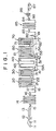
- FIG. 1 is an explanatory view showing the general arrangement of one embodiment of the steel strip continuous annealing apparatus according to the present invention.
- a steel strip feeder is provided at the inlet side of this continuous annealing apparatus as will be described below. Namely, a steel strip, which has been cold-rolled, is wound out of an uncoiler 12, connected to another steel strip in a welder 12, and rolling oil adhered to the surface of the steel strip is removed therefrom by a cleaning equipment 13.
- An inlet looper 14 is provided as a steel strip pool, so that connecting of a steel strip to another can be effected at the welder 12 without stopping the operation in the heating zone, and bridle rolls 15, 16 for isolating the tension of the steel strip are provided in front and rear of the inlet looper 14.
- a tension meter is incorporated in the tension meter roll 18 for detecting the actual tension of the steel strip, and the dancer roll 17 can control the tension of the steel strip by moving vertically due to the movement of the tension control means as will be described hereunder.
- the main body of continuous annealing furnace comprises a heating zone 20, a soaking zone 30, a first cooling zone 40, a second cooling zone 60 and a third cooling zone 70, all of which will be described in detail hereunder, respectively.
- Hearth rolls 21 for supporting the steel strip at the top and at the bottom and conveying same are provided in the heating zone 20 which further incorporates therein heating means for elevating the temperature of the steel strip to a predetermined temperature.
- the steel strip which has been elevated in temperature to the predetermined temperature in the heating zone 20, passes across deflector rolls 22 provided at the outlet of the heating zone 20, and is delivered to the soaking zone 30.
- Hearth rolls 31 for supporting the steel strip at the top and at the bottom and conveying same are provided in the soaking zone 30 incorporating therein soaking means for soaking the steel strip, which has been elevated in temperature in the heating zone 20 to a predetermined temperature.
- the steel strip, which has been soaked at a predetermined temperature in the soaking zone 30, passes across bridle rolls 42 provided at the outlet of the soaking zone 30, and is delivered to the first cooling zone 40.
- Bridle rolls 41, 42 for isolating the tension of the steel strip in the first cooling zone 40 from the tension of the steel strip forwardly and rearwardly thereof are provided at the inlet and outlet of the first cooling zone 40 which incorporates therein hearth rolls 43 for supporting the steel strip at the top and at the bottom and conveying same.
- plenum chambers 44 constituting forcible cooling means being opposed to the opposite surfaces of the steel strip being conveyed in the respective conveying passageways are provided at opposite sides of the respective conveying passageways through which the steel strip is vertically conveyed.
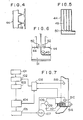
- HN gas as the gaseous atmosphere in the furnace is delivered into the plenum chambers 44 in a state of cooling gas through a water-cooled cooler 47 by the driving force of a circulating fan 46 driven by a motor 45, and the cooling gas, which has been delivered into the plenum chambers 44 in the compressed condition, is adapted to be blown out of slit-shaped blow-out nozzles 48 formed in the surface opposed to the steel strip toward the surface of the steel strip as shown in Figure 4 so that the cooling gas can rapidly cool the steel strip at a predetermined cooling rate.
- each plenum chamber 44 is divided in the widthwise direction by a plurality of partition walls 49, and, in flow-in portions of the respective compartments at the side of the circulating fan 46, there are provided flow rate regulating dampers 50, which are adjustable in opening degrees independently of one another. More specifically, in each plenum chamber 44, the respective flow rate regulating dampers 50 are suitably regulated, whereby the distribution of flow rates of the cooling gas blown out of the blow-out nozzles 48 in the widthwise direction is controlled, so that the steel strip can be uniformly rapidly cooled in the widthwise direction thereof.
- first cooling zone 40 provided at the lower portion of the first cooling zone 40 is a first bypass passageway 51 for directly passing the steel strip from the bridle roll 41 to the bridle roll 42, so that the steel strip, which has been fed from the soaking zone 30, can be bypassed directly to the second cooling zone 60 without passing through conveying passageways in the first.
- cooling zone 40 where the plenum chambers 44 are provided.
- heat isolating dampers 52 being rotatable between a condition indicated by solid lines and a condition indicated by broken lines in Figure 6, so as to form a passing region for allowing the steel strip to pass therethrough when the steel strip is conveyed through the first cooling zone 40 for being rapidly cooled and to divide the first bypass passageway 51 from the interior of the first cooling zone 40 when the steel strip passes through the first bypass passageway 51, so that the bad influence of the radiant heat emitted from the steel strip at a high temperature passing through the first bypass passageway 51 to the plenum chambers 44 can be prevented.
- helper rolls 51 A for supporting the steel strip and conveying same is provided in the first bypass passageway 51, and a strip thermometer 51 B for detecting the temperature of the steel strip and a roll thermometer 51 C for detecting the temperatures of the helper rolls 51 A, respectively. More specifically, the roll temperatures of the helper rolls 51 A are controlled in such a manner that the roll temperature come close to the temperatures of the steel strip at respective positions of rolls predictably calculated by a method of controlling the roll temperature which will be described hereunder.
- An annealing specification generator 101 is adapted to feed the annealing specification including the dimensions of the steel strip, heat pattern and the like to processor 102.
- This processor 102 calculates the maximum line speeds of the steel strip in the heating zone 20, soaking zone 30, the second cooling zone 60 and the third cooling zone 70 based on the annealing specification, and feeds the maximum line speeds for the respective zones to a common speed selector 103.
- This common speed selector 103 selects the lowest speed out of the highest line speeds of the respective zones as the common speed in the continuous annealing furnace and feeds same to a steel strip temperature calculator 104.
- This steel strip temperature calculator 104 predictably calculates the temperatures of the steel strip after cooling at positions where the respective helper rolls 51A are disposed in the first bypass passageway 51 based on the heating rates and the like of the heating zone 20 and soaking zone 30 at the common speed, and feeds the predicted results to a heater selector 105.
- the heater selector 105 feeds signals to a temperature indication controller 107 to control an electric current controller 108, so that the current flowing from a power source 109 to heaters 110 can be controlled.
- These heaters 110 may preferably have a construction capable of heating the entire area in the axial direction of the helper roll 51 A.
- the roll temperatures resulted from heating by these heaters 110 are detected by the roll thermometer 51C which feeds the detection signals to a learner 106, and the strip thermometer 51 B detects the strip temperatures at places and feeds signals to the learner 106.
- the general speed in the continuous annealing furnace is calculated by this control means, whereby the temperatures of the steel strip at places in the first bypass passageway 51 are predicted, so that the respective helper rolls 51 A can be heated by the heaters 110 to temperatures equal to the predicted temperatures, thereby enabling to keep very small the difference in temperature between the steel strip and the respective helper rolls 51 A.
- the temperatures of the rolls and the steel strip after heating are respectively detected by the thermometers, and the difference of the latter from the predicted temperature of the steel strip is calculated by the learner 106 and fed to processor 102, with the result that learning controls are affected, whefeby the difference between the predicted temperature of the steel strip and the actual temperature of the steel strip becomes small, so that proper current control of the heater can be effected and, when the annealing specification including the dimensions of the steel strip, heat patterns and the like are changed, an annealing operation with high yield can be attained by quickly changing the roll temperatures.
- a carry-out portion 53 for carrying the steel strip out of the furnace is provided at the lower portion of the first cooling zone 40, and a second bypass passageway 54 for directly carrying the steel strip out toward the steel sheet carry-out device provided which will be described hereinafter at the outlet of the main body of the continuous annealing furnace from the carry-out portion 53.
- the steel strip which has been soaked at a predetermined temperature in the soaking zone 30 and thereafter conveyed through the first bypass passageway 51, or rapidly cooled in the first cooling zone 40, can enter the second cooling zone 60 following the first cooling zone 40.
- the second cooling zone 60 is provided therein with hearth rolls 61 for supporting the steel strip at the top and at the bottom and conveying same and deflector rolls 62 disposed at the outlet thereof for deflecting the steel strip to the third cooling zone 70 that follows.
- Radiators 63 constituting hot-cold change-over means, four of which are arranged in series in the vertical direction as shown in Figures 8 and 9, are disposed at opposite sides of the respective conveying passageways, through which the steel strip is conveyed, in the second cooling zone 60.
- the radiators 63 each comprise a small letter 'U' shaped first tube 63A, a medium letter 'U' shaped second tube 63B and a large letter 'U' shaped third tube 63C, all of which are opposed to the surface of the steel strip being conveyed through the respective conveying passageways.
- a heating fluid pipe 65 for introducing heating gas through a change-over valve 64 and a cooling fluid pipe 67 for introducing cooling gas through a change-over valve 66.
- an exhaust fan 68 for discharging the heating gas or cooling gas, which has been introduced into the radiators 63. More specifically, the heating gas or cooling gas, which has been introduced into the radiators 63 by the switching operation of the change-over valve 64 or 66, passes through the first, second and third tubes 63A, 63B and 63C, being capable of slowly cooling or holding at a predetermined temperature the steel strip by the radiant heat emitted therefrom.
- the respective tubes 63A, 63B and 63C are each provided therein with a flow rate regulating valve, not shown.
- the flow rates of heating gas or cooling gas to the respective tubes 63A, 63B and 63C are regulated, whereby the distribution of radiant heat acting on the steel strip in the widthwise direction thereof is controlled, so that the steel strip can be uniformly slowly cooled or held at a predetermined temperature.
- the steel strip which has been slowly cooled or held at a predetermined temperature in the second cooling zone 60, subsequently can enter the third cooling zone 70.
- the third cooling zone 70 there are provided hearth rolls 71 for supporting the steel strip from above to below and vice versa and conveying same, and deflector rolls 72 for deflecting- and delivering the steel strip to the steel strip carry-out device are provided at the outlet of the third cooling zone.
- plenum chambers 73 are disposed at opposite sides of the respective conveying passageways, through which the steel strip is conveyed.
- HN gas as the gaseous atmosphere in the furnace is delivered into the inner space of plenum chambers 73 in a condition compressed by a circulating fan 76 driven by an electric motor 75 and in a condition cooled by a water-cooled cooler 74, blown out to the opposite sides of the steel strip from a plurality of blow-out openings penetrated in the surfaces of the plenum chambers 73 opposed to the respective conveying passageways for the steel strip, and can cool the steel ingot substantially to room temperature.
- the steel strip which has been cooled in the third cooling zone or rapidly cooled in the first cooling zone, thereafter passes through the second bypass passageway 54 and sent out, passes through deflector rolls 72, and is delivered into the steel strip carry-out device through a tension meter roll 81 incorporating therein a tension meter so as to constitute tension control means which will hereunder be described and a dancer roll 82, the vertical movement of which is controllable.
- the steel strip carry-out device comprises: an outer looper 85 provided in a section where the condition of tension is isolated by bridle rolls 83, 84 and making it possible to shear the steel strip .in a shearing machine 86 without stopping the operation of the main body of continuous annealing furnace; a shearing machine 86 for shearing the steel strip, which has been annealed, to a predetermined length; a recoiler 87 for winding up the steel strip, which has been shorn; and sampling means 88 including a sample punch and the like for picking up from the annealed steel strip specimens to be tested in mechanical, electromagnetic and other properties.
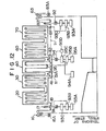
- the tension control means in the aforesaid continuous annealing apparatus is formed as follows. Namely, respective bridle rolls 16, 41, 42 and 83 are formed into cylinders each having axially uniform diameters so that the contact area between the steel strip and the roll can be made large to minimize the contact surface pressure therebetween, and the frictional coefficient therebetween is made high to increase the difference in tension between portions of the steel strip forwardly and rearwardly of the roll, so that the tension at the portions of the steel strip forwardly and rearwardly of the position where the rolls are provided, can be isolated. Consequently, the interior 'of the furnace is divided by adjacent bridle rolls 16, 41, 42 and 83, whereby a plurality of tension control blocks are formed which are variable in tension discontinuously from one to another.
- a tension control block defined by the bridle rolls 16 and 41 is set at a required tension condition by the dancer roll 17 controlled by a torque motor 91
- a tension control block defined by the bridle rolls 42 and 83 is set at a required tension condition by the dancer roll 82 controlled by a torque motor 92.
- the dancer rolls 17, 82 which have been vertically displaced to control the tensions are restored to a vertically central position, i.e., an original position by changing the rotational speed of the driving motors 16A, 83A.
- the tension required for the respective tension control blocks are transmitted to tension controllers 93B as command signals 93A, the tension controllers 93B, based on a comparison between output values from the tension meter rolls 18, 81 and the command signals 93A, rotate the torque motors 91, 92 in the normal or reverse direction for the number of rotations required through motor torque controllers 93C to vertically move the dancer rolls 17, 82 so that the tensions of the respective tension control blocks can be controlled to the conditions required by the command signals 93A.
- either one of the bridle rolls 41 or the bridle roll 42 (in this embodiment, the bridle roll 42) is connected thereto with a rotatably driving motor 94 constituting a tension control mechanism and rotating the bridle rolls 41, 42 in such a manner that the steel strip can be conveyed at a predetermined conveying speed based on a steel strip conveying speed command 94A.
- a tension meter roll 95 incorporating therein a tension meter capable of detecting the actual tension condition in a tension control block is provided in the tension control block defined by the bridle roll 41 and the bridle roll 42.
- the tension required for the tension control block defined by the bridle roll 41 and the bridle roll 42 is transmitted to a tension controller 95B as a command signal 95A
- the tension controller 95B based on comparison between the command signal 95A and an output value of the tension meter roll 95, controls the number of rotations of the rotatably driving motor 94 through a rotation number controller 95C, whereby the rotation of the bridle roll 42 is varied, so that the tension in this tension control block can be controlled to the required condition.
- the number of rotations of the rotatably driving motor 94 is fed back to the rotation number controller 95C through a rotation number detector 95D.
- the steel strip Upon being cold-rolled, the steel strip is wound out by an uncoiler 11, connected to another steel strip in the welder 12, and rolling oil adhered to the surface of the steel strip is removed therefrom by the cleaning equipment 13, and thereafter, delivered into the main body of the annealing furnace through the inlet looper 14 and the like.
- the steel strip is subjected to annealing treatment in a heat cycle corresponding to the grade of steel thereof, passes through the outlet looper 85, is shorn to a predetermined length by the shearing machine 86, and thereafter, wound up by the recoiler 87.
- the steel strip is one for producing the soft black tinplate
- the steel strip is subjected to the annealing treatment in the heat cycle as shown in Figure 13. More specifically, the steel strip is heated in the heating zone 20, soaked at a temperature of 700 to 800°C in the soaking zone 30, passes through the first bypass passageway 51, and is directly introduced into the second cooling zone 60 without passing through the interior of the first cooling zone 40.
- the steel strip which has been introduced into the second cooling zone 60, receives at the opposite surfaces thereof the radiant heat emitted from the radiators 63 constituting the hot-cold change-over means in the second cooling zone 60 and into which the cooling gas is caused to flow by -opening the change-over valve 66, and is slowly cooled to about 450°C.
- the flow rate regulating valves provided in the respective tubes 63A, 63B and 63C of the radiator 63 are regulated with one another, whereby the radiant heat emitted from the radiator 63 in the widthwise direction is controlled, so that the steel strip can be slowly cooled under a uniform distribution in the widthwise direction thereof.
- the steel strip, which has been slowly cooled in the second cooling zone 60 as described above, is further introduced into the third cooling zone 70, cooled to substantially room temperature by the cooling gas blown out of the blow-out openings 77 of the plenum chambers 73 provided in the third cooling zone 70, and thereafter, discharged to the outside of the furnace.
- this steel strip for producing the black tinplates being at high temperature passes through the first bypass passageway 51, the heat isolating dampers 52 provided at the respective lower end portions of the plenum chambers 44 in the first cooling zone 40 are closed, so that such adverse effects can be prevented that the radiant heat emitted from the steel strip enters the inner space of the first cooling zone 40 to cause thermal deformation to the plenum chambers 44 and the like.
- this first bypass passageway 51 such a control is effected that the roll temperatures of the respective helper rolls 51 A come close to the temperatures of the steel strip at respective positions of rolls predictably calculated. Namely, the difference in temperature between the steel strip and the helper rolls 51 A disappears, thereby enabling to obtain annealed black tinplates with high quality having good shape.
- the steel strip is one for producing cold-rolled steel sheets for drawing or soft black tinplates
- the steel strip is annealed under a heat cycle as shown in Figure 14. More particularly, the steel strip is elevated in temperature in the heating zone 20, soaked at a temperature of 700 to 800°C in the soaking zone, and then, introduced into the first cooling zone 40.
- the steel strips, which have been introduced into the first cooling zone 40 are rapidly cooled to a temperature of about 300 to 500°C at a cooling rate of approximately 30 to 50°C/sec., for example, receiving at the surfaces thereof the cooled HN gas blown out of the slit-shaped blow-out nozzles 48 of the plenum chambers 44 constituting the forcible cooling means.
- the flow rates of cooling gas flowing into the compartments divided by the partition walls 49 in the respective plenum chambers 44 are regulated by operating the respective flow rate regulating dampers 50, whereby the distribution of flow rates of the blow-out nozzles 48 in the widthwise direction are controlled, so that the steel strips can be rapidly cooled in the condition where the distribution in temperature in the widthwise direction of the steel strip is made uniform.
- the steel strips which have been rapidly cooled in the first cooling zone 40 as deserved above, receiving the radiant heat of the radiators 63, into which heating gas is caused to flow by opening the change-over valves 64 in the second cooling zone 60, are held in the condition of temperature upon being rapidly cooled for 1 to 5 minutes to be subjected to the overaging treatment, softened satisfactorily, thereafter, cooled to substantially room temperature by the cooling action of the plenum chambers 73 in the third cooling zone 70, and then, carried out of the furnace.
- a tension of the steel strip in the tension control block defined by the bridle rolls 16 and 41, i.e., in the heating zone 20 and the soaking zone 30 is set at a required tension condition through a tension controller 93B operated based on a command signal 93A and an output value from the tension meter roll 18, a torque motor 91 controlled by a motor torque controller 93C and the dancer roll 17.
- a tension of the steel strip in the tension control block defined by the bridle rolls 42 and 83 i.e., in a second cooling zone 60 and a third cooling zone 70 is likewise maintained at a required tension condition by vertical moving a dancer roll 82.
- a tension of the steel strip in the tension control block defined by the bridle rolls 41 and 42 i.e., in the first cooling zone 40 is set at a required low tension condition by a tension controller 95B operated based on a command signal 95A and an output value from a tension meter roll 95, a rotatably driving motor 94 driven by a rotational number controller 95C and a bridle roll 42.
- the tensions in the respective tension control blocks are maintained at required tension conditions independently of one another, and the tension of the steel strip in the first cooling zone 40 is set at a tension condition lower than the tensions in the tension control blocks disposed forwardly and rearwardly of the first cooling zone 40, and hence, despite irregularities in cooling tend to occur in the steel strip at a high cooling rate, irregular shapes of the steel strip, cooling buckling and the like do not occur.
- the steel strip is one for producing the high-strength cold-rolled steel sheets
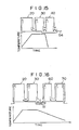
- the steel strip is annealed under the heat cycle shown in Figure 15. More specifically, the steel strip is heated in the heating zone 20, soaked to a temperature of 800 to 850°C to partially generate y phase in the ferrite in the soaking zone 30, and thereafter, introduced into the first cooling zone 40.
- the steel strip which has been introduced into the first cooling zone 40, receives at the surfaces thereof the cooling gas of high flow rate blown out of the slit-shaped blow-out nozzles 48 of the plenum chambers 44 constituting the forcible cooling means in the first cooling zone 40, the distribution of blow-out quantities from the flow-out nozzles 48 in the widthwise direction is regulated by operating the flow rate regulating dampers 50 in the plenum chambers 44, so that the steel strip can be rapidly cooled in the condition where the distribution in temperature in the widthwise direction of the steel strip is made uniform.
- the steel strip which has been rapidly cooled to a low temperature in the first cooling zone 40, passes through the carry-out portion 53, is introduced into the second bypass passageway 54 and directly introduced to the steel strip carry-out device outside the furnace without passing through the second cooling zone 60 and the third cooling zone 70.
- the steel strip is one for producing the silicon steel sheets
- the steel strip is annealed under a heat cycle shown as the heat cycle in Figure 16. More specifically, the steel strip is heated in the heating zone 20, soaked to a comparatively high temperature of approximately 800 to 1000°C, thereafter, passes through the first bypass passageway 51, i.e., without passing through the first cooling zone 40, is directly introduced into the second cooling zone 60, and further led to the third cooling zone 70.
- the steel strip is cooled through the cooling actions by the radiators 63 constituting the hot-cold change-over means and the plenum chambers 73 constituting the forcible cooling means.
- this first bypass passageway 51 similarly to the above-described case of annealing the black tinplates, the roll temperatures of the respective helper rolls 51A are controlled, and the difference ' in temperature between the steel strip and the helper rolls 51 A disappears, thereby enabling to obtain annealed silicon steel sheets with high quality having good shape.
- the steel strips different in the grades of steel such as the black tinplate, soft black tinplate, cold-rolled steel sheet for drawing, high-strength cold-rolled steel sheet, silicon steel sheet can be annealed in a single continuous annealing apparatus. Consequently, even if the quantities of the various grades of steel required to be treated are respectively small, the operating efficiency of this continuous annealing apparatus can be maintained to be high.
- the tensions of the steel strip in the line of the continuous annealing apparatus can be set independently of one another in a plurality of tension control blocks and the tension of the steel strip in the first cooling zone 40 can be set at a value lower than the tensions of the steel strip in the zones disposed forwardly and rearwardly of the first cooling zone 40, so that irregular shapes of the steel strip or cooling buckling can be prevented from occurring.
- the first cooling zone 40 is defined by the bridle rolls 41, 42 which are disposed forwardly and rearwardly of the first cooling zone 40, and the tension in this tension control block is set at a value lower than those in other tension control blocks.
- the tension of the steel strip in the tension control block corresponding to both the outlet of the heating zone and the soaking zone is set at a value lower than that in the tension control block, then, despite the steel strip, is softened under high temperature and the yield point thereof is decreased, it becomes possible to prevent the quantities of plastic deformation of the steel strip from increasing.
- the grades of steel different in a required heat cycle can be efficiently annealed
- the thermal effects of the radiant heat emitted from the steel strip, while the steel strip bypasses the first cooling zone, rendered to the interior of the first cooling zone can be prevented
- proper tensions are applied to the respective zones in the furnace independently of one another, so that a stable operating condition can be ensured.
Landscapes
- Chemical & Material Sciences (AREA)
- Engineering & Computer Science (AREA)
- Physics & Mathematics (AREA)
- Thermal Sciences (AREA)
- Crystallography & Structural Chemistry (AREA)
- Mechanical Engineering (AREA)
- Materials Engineering (AREA)
- Metallurgy (AREA)
- Organic Chemistry (AREA)
- Heat Treatment Of Strip Materials And Filament Materials (AREA)
Description
- The invention refers to a steel strip continuous annealing apparatus of the general type comprising a heating-soaking zone for heating a steel strip to a predetermined temperature and for soaking the steel strip at said temperature; a first cooling zone subsequent to said heating-soaking zone for rapidly cooling the steel strip at a predetermined cooling rate; first forcible cooling means incorporated into said first cooling zone for operation of the rapid cooling; a final cooling zone for cooling the steel strip to substantially room temperature; second forcible cooling means being incorporated into said final cooling zone for operation of the cooling to substantially room temperature; a steel strip feeder for feeding the steel strip into said heating-soaking zone and a steel strip carry-out device for carrying the steel strip out of said final cooling zone. A steel strip continuous annealing apparatus of the aforedescribed type is known from GB-A-1344460. Continuous annealing apparatuses of this type are formed into peculiar predetermined configurations depending upon grades of steel, thicknesses of sheet, temperatures for heating and soaking, cooling conditions and the like.
- More specifically, a continuous annealing apparatus for producing black tinplates, for example, has a function that, a steel strip having a sheet thickness of 0.15 to 0.6 mm and a sheet width of 600 to 1000 mm is soaked at a temperature of 700 to 800°C, thereafter, slowly cooled to about 450°C from the temperature described above, and further, rapidly cooled to 100°C to substantially room temperature, where the steel strip is not oxidized, outside the furnace. Consequently, the continuous annealing apparatus comprises a heating, a soaking and a slow cooling and rapid cooling zones. In contrast thereto, a continuous annealing apparatus for producing cold-rolled steel sheets for drawing has a function that, a steel strip for producing cold-rolled steel sheet for drawing having a sheet thickness of 0.4 to 1.6 mm and a sheet width of 800 to 1500 mm or a steel strip for producing a soft black tinplate having a sheet thickness of 0.15 to 0.6 mm and a sheet width of 600 to 1000 mm is soaked to a temperature of 700 to 850°C, thereafter, rapidly cooled to a temperature of 300 to 500°C at a cooling rate of approximately 10 to 100°C/sec, subjected to an overaging treatment being held at the temperature of 300 to 500°C for 1 to 5 minutes, so as to be satisfactorily softened, and then, rapidly cooled. Consequently, the continuous annealing apparatus comprises a heating, a soaking, a rapid cooling, an overaging and a final cooling zone. Furthermore, a continuous annealing apparatus for producing high-strength cold-rolled steel sheet having a mixed structure has a function that, a steel strip having a sheet thickness and a sheet width similar to those of the cold-rolled steel sheet for drawing as described above is heated to a temperature of 800 to 850°C. caused to partially generate y phase in a ferrite structure, rapidly cooled at a cooling rate of approximately 10 to 100°C/sec and turned into a product as it is. Further, a continuous annealing apparatus for producing silicon steel sheets has a function that, a steel sheet having a sheet thickness of 0.3 to 0.7 mm and a sheet width of 600 to 1000 mm can be heated to a comparatively high temperature of 800 to 1000°C and soaked, and thereafter, cooled, and consequently. comprises a heating zone, a soaking zone and a cooling zone. As has been described hereinabove, each continuous annealing apparatus is required to have a peculiar heat cycle depending on the material quality of the steel sheet to be annealed and a peculiar configuration depending on the dimensions of the steel . sheet, and, it is difficult to treat in one and the same continuous annealing apparatus the black tinplates, cold-rolled steel sheet for drawing, soft black tinplates, high-strength cold-rolled steel sheets, silicon steel sheets or the like, which are different in heat cycle and dimensions.
- However, it is uneconomical to set the rate of conveying the steel strip at an excessively small value in a continuous annealing apparatus because the continuous annealing apparatuses each have a production capacity of 20,000 to 40,000 t/mon on average. Consequently, it is apparently inadvisable for an enterprise having an amount of customers demand insufficient to constantly and sufficiently operate the respective types of continuous annealing apparatuses to possess the above-described continuous annealing apparatuses meeting the conditions required for the types of steel strips. From the viewpoint as described above, necessity has been voiced to make it possible to selectively treat the black tinplates, cold-rolled steel sheets, high-strength cold-rolled steel sheets or silicon steel sheets in a single continuous annealing apparatus.
- Furthermore, the continuous annealing apparatus froms a considerably long continuous line, and therefore, in order to maintain a stabilized operating condition in the furnace it is necessary to render proper tensions to the steel strip in the furnace. For example, in the rapid cooling zone where the steel strip is rapidly cooled from the soaked condition, cooling irregularities tend to occur in the steel strip because the steel strip is cooled at a high cooling rate, if the tension is expensively high, then irregular shapes of the steel strip and cooling buckling and the like tend to occur. Consequently, the tension of the steel strip in the rapid cooling zone is required to be set at the level lower than other zones.
- However, in the conventional continuous annealing apparatus, the tension acting on the steel strip in the furnace is regulated to be substantially uniform, and hence, the tension of the steel strip only in the rapid cooling zone cannot be set at a discontinuously low value.
- More specifically, in the conventional continuous annealing apparatus, the conditions of tension in the respective zones of the furnace cannot be controlled independently of one another, thus, presenting problems including ruptures in the steel strip due to the movement of the steel strip in a zigzag fashion, damages caused to the furnace, fluctuations in width of the steel strip, irregular shapes of the steel strip, local fluctuations in shapes of the steel strip and the like.
- From GB-A-1435651, a continuous annealing furnace is known, wherein the passage of travelling steel strip is changeable to extend through a water-quenching zone or through a bypass passageway to avoid said water-quenching zone. In operation, said prior art annealing furnace, for annealing strip of a thickness less than 0.5 mm, only said gas-jet cooling zone is employed as a rapid cooling zone and said zone is connected directly to a following carbon precipitation treatment zone through said bypass passageway, which is provided parallel to the water-quenching zone. If, however, steel strip of a thickness more than 0.6 mm is annealed, said gas-jet cooling zone and then said water-quenching zone are employed as a rapid cooling zone without making use of the bypass passageway.
- The furnace according to GB-A-14 35 651 permits heat treatments only for very few steel sheet grades because of its narrow application.
- The present invention aims to remedy the deficiencies of the prior art and to provide a steel strip continuous annealing apparatus of the type as indicated in the preamble portion of
claim 1, wherein, steel strips of different dimensions and with different. heat treatment requirements can be efficiently and stably annealed. - To achieve the above-desired object, according to the invention, there is provided a second cooling zone subsequent to said first cooling zone for slowly cooling the steel strip or holding the steel strip at a predetermined temperature; hot-cold change-over means in said second cooling zone for selectively either slowly cooling the steel strip or holding the steel strip at a predetermined temperature; means for directly bypassing the steel strip from the heating-soaking zone through a first bypass passageway to said second cooling zone; and means for directly bypassing the steel strip from the first cooling zone through a second bypass passageway to said steel strip carry-out device.
- The inventive continuous annealing apparatus provides a valuable progress in the art and in particular, the inventive combination of the two altsmais bypass passageways and the second cooling zone both for slowly cooling and holding the temperature allows the processing of many multigrades of steel with different thicknesses.
- Preferred embodiments and further improvements of the inventive steel strip continuous annealing apparatus are described in the subclaims.
- The nature of the invention will become more apparent with reference to the following description, taken in conjunction with the accompanying drawings, wherein !ike reference numerals denote like elements, and in which:
- Figure 1 is a general arrangement view showing one embodiment of the steel strip continuous annealing apparatus according to the present invention;
- Figure 2 is a sectional view showing the interior of the first cooling zone;
- Figure 3 is a sectional view taken along the line III-III in Figure 2;
- Figure 4 is a sectional view enlargedly showing the essential portions in Figure 2;
- Figure 5 is a sectional view taken along the line V-V in Figure 2;
- Figure 6 is a sectional view showing the essential portions other than the ones above-described in Figure 4;
- Figure 7 is a circuit diagram showing method of controlling the temperatures of rolls;
- Figure 8 is a sectional view showing the interior of the second cooling zone;
- Figure 9 is a sectional view taken along the line IX-IX in Figure 8;
- Figure 10 is a sectional view showing the interior of the third cooling zone;
- Figure 11 is a sectional view taken along the line XI-XI in Figure 10;
- Figure 12 is an explanatory view showing the steel strip tension control means and the steel strip tensions in the furnace thereby;'
- Figure 13 is a diagram showing the heat cycle for the black tinplate;
- Figure 14 is a diagram showing the heat cycle for the soft black tinplate or cold-rolled steel sheet for drawing;
- Figure 15 is a diagram showing the heat cycle for the high tension cold-rolled steel sheet;
- Figure 16 is a diagram showing the heat cycle for the silicon steel sheet; and
- Figure· 17 is a diagram showing the heat cycle for the various types of steel strips experimentally obtained by the present inventor.
- Figure 1 is an explanatory view showing the general arrangement of one embodiment of the steel strip continuous annealing apparatus according to the present invention. A steel strip feeder is provided at the inlet side of this continuous annealing apparatus as will be described below. Namely, a steel strip, which has been cold-rolled, is wound out of an
uncoiler 12, connected to another steel strip in awelder 12, and rolling oil adhered to the surface of the steel strip is removed therefrom by acleaning equipment 13. Aninlet looper 14 is provided as a steel strip pool, so that connecting of a steel strip to another can be effected at thewelder 12 without stopping the operation in the heating zone, andbridle rolls 15, 16 for isolating the tension of the steel strip are provided in front and rear of theinlet looper 14. - A dancer roll 17 and a
tension meter roll 18, both of which constitute tension control means as will be described hereinafter, are provided between thebridle roll 16 and the inlet of the main body of furnace. A tension meter is incorporated in thetension meter roll 18 for detecting the actual tension of the steel strip, and the dancer roll 17 can control the tension of the steel strip by moving vertically due to the movement of the tension control means as will be described hereunder. In order to make it possible to continuously anneal the steel strips of every grade of steel, the main body of continuous annealing furnace comprises aheating zone 20, asoaking zone 30, afirst cooling zone 40, asecond cooling zone 60 and athird cooling zone 70, all of which will be described in detail hereunder, respectively. - Hearth rolls 21 for supporting the steel strip at the top and at the bottom and conveying same are provided in the
heating zone 20 which further incorporates therein heating means for elevating the temperature of the steel strip to a predetermined temperature. The steel strip, which has been elevated in temperature to the predetermined temperature in theheating zone 20, passes across deflector rolls 22 provided at the outlet of theheating zone 20, and is delivered to thesoaking zone 30. - Hearth rolls 31 for supporting the steel strip at the top and at the bottom and conveying same are provided in the
soaking zone 30 incorporating therein soaking means for soaking the steel strip, which has been elevated in temperature in theheating zone 20 to a predetermined temperature. The steel strip, which has been soaked at a predetermined temperature in thesoaking zone 30, passes acrossbridle rolls 42 provided at the outlet of thesoaking zone 30, and is delivered to thefirst cooling zone 40. - Bridle rolls 41, 42 for isolating the tension of the steel strip in the
first cooling zone 40 from the tension of the steel strip forwardly and rearwardly thereof are provided at the inlet and outlet of thefirst cooling zone 40 which incorporates thereinhearth rolls 43 for supporting the steel strip at the top and at the bottom and conveying same. - As shown in Figures 2 and 3, in this
first cooling zone 40,plenum chambers 44 constituting forcible cooling means being opposed to the opposite surfaces of the steel strip being conveyed in the respective conveying passageways are provided at opposite sides of the respective conveying passageways through which the steel strip is vertically conveyed. HN gas as the gaseous atmosphere in the furnace is delivered into theplenum chambers 44 in a state of cooling gas through a water-cooledcooler 47 by the driving force of a circulatingfan 46 driven by amotor 45, and the cooling gas, which has been delivered into theplenum chambers 44 in the compressed condition, is adapted to be blown out of slit-shaped blow-outnozzles 48 formed in the surface opposed to the steel strip toward the surface of the steel strip as shown in Figure 4 so that the cooling gas can rapidly cool the steel strip at a predetermined cooling rate. - Further, as shown in Figure 5, the interior of each
plenum chamber 44 is divided in the widthwise direction by a plurality ofpartition walls 49, and, in flow-in portions of the respective compartments at the side of the circulatingfan 46, there are provided flowrate regulating dampers 50, which are adjustable in opening degrees independently of one another. More specifically, in eachplenum chamber 44, the respective flowrate regulating dampers 50 are suitably regulated, whereby the distribution of flow rates of the cooling gas blown out of the blow-outnozzles 48 in the widthwise direction is controlled, so that the steel strip can be uniformly rapidly cooled in the widthwise direction thereof. - Furthermore, provided at the lower portion of the
first cooling zone 40 is afirst bypass passageway 51 for directly passing the steel strip from thebridle roll 41 to thebridle roll 42, so that the steel strip, which has been fed from thesoaking zone 30, can be bypassed directly to thesecond cooling zone 60 without passing through conveying passageways in the first. coolingzone 40 where theplenum chambers 44 are provided. Furthermore, provided at the lower ends of theplenum chambers 44 being opposed to thefirst bypass passageway 51 in thefirst cooling zone 40 areheat isolating dampers 52 being rotatable between a condition indicated by solid lines and a condition indicated by broken lines in Figure 6, so as to form a passing region for allowing the steel strip to pass therethrough when the steel strip is conveyed through thefirst cooling zone 40 for being rapidly cooled and to divide thefirst bypass passageway 51 from the interior of thefirst cooling zone 40 when the steel strip passes through thefirst bypass passageway 51, so that the bad influence of the radiant heat emitted from the steel strip at a high temperature passing through thefirst bypass passageway 51 to theplenum chambers 44 can be prevented. - Further, helper rolls 51 A for supporting the steel strip and conveying same is provided in the
first bypass passageway 51, and a strip thermometer 51 B for detecting the temperature of the steel strip and a roll thermometer 51 C for detecting the temperatures of the helper rolls 51 A, respectively. More specifically, the roll temperatures of the helper rolls 51 A are controlled in such a manner that the roll temperature come close to the temperatures of the steel strip at respective positions of rolls predictably calculated by a method of controlling the roll temperature which will be described hereunder. - Description will hereunder be given of the method of controlling the roll temperature of the above-described helper rolls 51 A with reference to Figure 7. An
annealing specification generator 101 is adapted to feed the annealing specification including the dimensions of the steel strip, heat pattern and the like toprocessor 102. Thisprocessor 102 calculates the maximum line speeds of the steel strip in theheating zone 20, soakingzone 30, thesecond cooling zone 60 and thethird cooling zone 70 based on the annealing specification, and feeds the maximum line speeds for the respective zones to acommon speed selector 103. - This
common speed selector 103 selects the lowest speed out of the highest line speeds of the respective zones as the common speed in the continuous annealing furnace and feeds same to a steelstrip temperature calculator 104. This steelstrip temperature calculator 104 predictably calculates the temperatures of the steel strip after cooling at positions where the respective helper rolls 51A are disposed in thefirst bypass passageway 51 based on the heating rates and the like of theheating zone 20 and soakingzone 30 at the common speed, and feeds the predicted results to aheater selector 105. - The
heater selector 105 feeds signals to atemperature indication controller 107 to control an electriccurrent controller 108, so that the current flowing from apower source 109 toheaters 110 can be controlled. Theseheaters 110 may preferably have a construction capable of heating the entire area in the axial direction of the helper roll 51 A. - The roll temperatures resulted from heating by these
heaters 110 are detected by the roll thermometer 51C which feeds the detection signals to alearner 106, and the strip thermometer 51 B detects the strip temperatures at places and feeds signals to thelearner 106. - Consequently, the general speed in the continuous annealing furnace is calculated by this control means, whereby the temperatures of the steel strip at places in the
first bypass passageway 51 are predicted, so that the respective helper rolls 51 A can be heated by theheaters 110 to temperatures equal to the predicted temperatures, thereby enabling to keep very small the difference in temperature between the steel strip and the respective helper rolls 51 A. Furthermore, the temperatures of the rolls and the steel strip after heating are respectively detected by the thermometers, and the difference of the latter from the predicted temperature of the steel strip is calculated by thelearner 106 and fed toprocessor 102, with the result that learning controls are affected, whefeby the difference between the predicted temperature of the steel strip and the actual temperature of the steel strip becomes small, so that proper current control of the heater can be effected and, when the annealing specification including the dimensions of the steel strip, heat patterns and the like are changed, an annealing operation with high yield can be attained by quickly changing the roll temperatures. - Furthermore, a carry-out
portion 53 for carrying the steel strip out of the furnace is provided at the lower portion of thefirst cooling zone 40, and asecond bypass passageway 54 for directly carrying the steel strip out toward the steel sheet carry-out device provided which will be described hereinafter at the outlet of the main body of the continuous annealing furnace from the carry-outportion 53. - The steel strip, which has been soaked at a predetermined temperature in the soaking
zone 30 and thereafter conveyed through thefirst bypass passageway 51, or rapidly cooled in thefirst cooling zone 40, can enter thesecond cooling zone 60 following thefirst cooling zone 40. Thesecond cooling zone 60 is provided therein with hearth rolls 61 for supporting the steel strip at the top and at the bottom and conveying same and deflector rolls 62 disposed at the outlet thereof for deflecting the steel strip to thethird cooling zone 70 that follows. -
Radiators 63 constituting hot-cold change-over means, four of which are arranged in series in the vertical direction as shown in Figures 8 and 9, are disposed at opposite sides of the respective conveying passageways, through which the steel strip is conveyed, in thesecond cooling zone 60. Theradiators 63 each comprise a small letter 'U' shapedfirst tube 63A, a medium letter 'U' shapedsecond tube 63B and a large letter 'U' shapedthird tube 63C, all of which are opposed to the surface of the steel strip being conveyed through the respective conveying passageways. Connected to the inlet side of theradiators 63 are aheating fluid pipe 65 for introducing heating gas through a change-over valve 64 and a coolingfluid pipe 67 for introducing cooling gas through a change-overvalve 66. Furthermore, connected to the outlet side of theradiators 63 is anexhaust fan 68 for discharging the heating gas or cooling gas, which has been introduced into theradiators 63. More specifically, the heating gas or cooling gas, which has been introduced into theradiators 63 by the switching operation of the change-overvalve 64 or 66, passes through the first, second andthird tubes radiator 63, therespective tubes respective tubes - The steel strip, which has been slowly cooled or held at a predetermined temperature in the
second cooling zone 60, subsequently can enter thethird cooling zone 70. In thethird cooling zone 70, there are provided hearth rolls 71 for supporting the steel strip from above to below and vice versa and conveying same, and deflector rolls 72 for deflecting- and delivering the steel strip to the steel strip carry-out device are provided at the outlet of the third cooling zone. - Furthermore, as shown in Figures 10 and 11, in the
third cooling zone 70,plenum chambers 73 are disposed at opposite sides of the respective conveying passageways, through which the steel strip is conveyed. HN gas as the gaseous atmosphere in the furnace is delivered into the inner space ofplenum chambers 73 in a condition compressed by a circulatingfan 76 driven by anelectric motor 75 and in a condition cooled by a water-cooledcooler 74, blown out to the opposite sides of the steel strip from a plurality of blow-out openings penetrated in the surfaces of theplenum chambers 73 opposed to the respective conveying passageways for the steel strip, and can cool the steel ingot substantially to room temperature. - The steel strip, which has been cooled in the third cooling zone or rapidly cooled in the first cooling zone, thereafter passes through the
second bypass passageway 54 and sent out, passes through deflector rolls 72, and is delivered into the steel strip carry-out device through atension meter roll 81 incorporating therein a tension meter so as to constitute tension control means which will hereunder be described and adancer roll 82, the vertical movement of which is controllable. - The steel strip carry-out device comprises: an
outer looper 85 provided in a section where the condition of tension is isolated by bridle rolls 83, 84 and making it possible to shear the steel strip .in a shearingmachine 86 without stopping the operation of the main body of continuous annealing furnace; a shearingmachine 86 for shearing the steel strip, which has been annealed, to a predetermined length; arecoiler 87 for winding up the steel strip, which has been shorn; and sampling means 88 including a sample punch and the like for picking up from the annealed steel strip specimens to be tested in mechanical, electromagnetic and other properties. - Further, the tension control means in the aforesaid continuous annealing apparatus is formed as follows. Namely, respective bridle rolls 16, 41, 42 and 83 are formed into cylinders each having axially uniform diameters so that the contact area between the steel strip and the roll can be made large to minimize the contact surface pressure therebetween, and the frictional coefficient therebetween is made high to increase the difference in tension between portions of the steel strip forwardly and rearwardly of the roll, so that the tension at the portions of the steel strip forwardly and rearwardly of the position where the rolls are provided, can be isolated. Consequently, the interior 'of the furnace is divided by adjacent bridle rolls 16, 41, 42 and 83, whereby a plurality of tension control blocks are formed which are variable in tension discontinuously from one to another.
- More specifically, as shown in Figure 12, a tension control block defined by the bridle rolls 16 and 41 is set at a required tension condition by the dancer roll 17 controlled by a torque motor 91, and a tension control block defined by the bridle rolls 42 and 83 is set at a required tension condition by the
dancer roll 82 controlled by atorque motor 92. Here, the dancer rolls 17, 82, which have been vertically displaced to control the tensions are restored to a vertically central position, i.e., an original position by changing the rotational speed of the drivingmotors tension controllers 93B ascommand signals 93A, thetension controllers 93B, based on a comparison between output values from the tension meter rolls 18, 81 and the command signals 93A, rotate thetorque motors 91, 92 in the normal or reverse direction for the number of rotations required throughmotor torque controllers 93C to vertically move the dancer rolls 17, 82 so that the tensions of the respective tension control blocks can be controlled to the conditions required by the command signals 93A. - Furthermore, either one of the bridle rolls 41 or the bridle roll 42 (in this embodiment, the bridle roll 42) is connected thereto with a
rotatably driving motor 94 constituting a tension control mechanism and rotating the bridle rolls 41, 42 in such a manner that the steel strip can be conveyed at a predetermined conveying speed based on a steel strip conveyingspeed command 94A. A tension meter roll 95 incorporating therein a tension meter capable of detecting the actual tension condition in a tension control block is provided in the tension control block defined by thebridle roll 41 and thebridle roll 42. The tension required for the tension control block defined by thebridle roll 41 and thebridle roll 42 is transmitted to atension controller 95B as acommand signal 95A, thetension controller 95B, based on comparison between thecommand signal 95A and an output value of the tension meter roll 95, controls the number of rotations of therotatably driving motor 94 through arotation number controller 95C, whereby the rotation of thebridle roll 42 is varied, so that the tension in this tension control block can be controlled to the required condition. In addition, the number of rotations of therotatably driving motor 94 is fed back to therotation number controller 95C through arotation number detector 95D. - Description will hereunder be given of action in the above-described embodiment. Upon being cold-rolled, the steel strip is wound out by an
uncoiler 11, connected to another steel strip in thewelder 12, and rolling oil adhered to the surface of the steel strip is removed therefrom by thecleaning equipment 13, and thereafter, delivered into the main body of the annealing furnace through theinlet looper 14 and the like. The steel strip is subjected to annealing treatment in a heat cycle corresponding to the grade of steel thereof, passes through theoutlet looper 85, is shorn to a predetermined length by the shearingmachine 86, and thereafter, wound up by therecoiler 87. - Here, in this case the steel strip is one for producing the soft black tinplate, the steel strip is subjected to the annealing treatment in the heat cycle as shown in Figure 13. More specifically, the steel strip is heated in the
heating zone 20, soaked at a temperature of 700 to 800°C in the soakingzone 30, passes through thefirst bypass passageway 51, and is directly introduced into thesecond cooling zone 60 without passing through the interior of thefirst cooling zone 40. The steel strip, which has been introduced into thesecond cooling zone 60, receives at the opposite surfaces thereof the radiant heat emitted from theradiators 63 constituting the hot-cold change-over means in thesecond cooling zone 60 and into which the cooling gas is caused to flow by -opening the change-overvalve 66, and is slowly cooled to about 450°C. Here, the flow rate regulating valves provided in therespective tubes radiator 63 are regulated with one another, whereby the radiant heat emitted from theradiator 63 in the widthwise direction is controlled, so that the steel strip can be slowly cooled under a uniform distribution in the widthwise direction thereof. The steel strip, which has been slowly cooled in thesecond cooling zone 60 as described above, is further introduced into thethird cooling zone 70, cooled to substantially room temperature by the cooling gas blown out of the blow-outopenings 77 of theplenum chambers 73 provided in thethird cooling zone 70, and thereafter, discharged to the outside of the furnace. In addition, in this case this steel strip for producing the black tinplates being at high temperature passes through thefirst bypass passageway 51, theheat isolating dampers 52 provided at the respective lower end portions of theplenum chambers 44 in thefirst cooling zone 40 are closed, so that such adverse effects can be prevented that the radiant heat emitted from the steel strip enters the inner space of thefirst cooling zone 40 to cause thermal deformation to theplenum chambers 44 and the like. - Furthermore, in this
first bypass passageway 51, such a control is effected that the roll temperatures of the respective helper rolls 51 A come close to the temperatures of the steel strip at respective positions of rolls predictably calculated. Namely, the difference in temperature between the steel strip and the helper rolls 51 A disappears, thereby enabling to obtain annealed black tinplates with high quality having good shape. - In this case the steel strip is one for producing cold-rolled steel sheets for drawing or soft black tinplates, the steel strip is annealed under a heat cycle as shown in Figure 14. More particularly, the steel strip is elevated in temperature in the
heating zone 20, soaked at a temperature of 700 to 800°C in the soaking zone, and then, introduced into thefirst cooling zone 40. The steel strips, which have been introduced into thefirst cooling zone 40, are rapidly cooled to a temperature of about 300 to 500°C at a cooling rate of approximately 30 to 50°C/sec., for example, receiving at the surfaces thereof the cooled HN gas blown out of the slit-shaped blow-outnozzles 48 of theplenum chambers 44 constituting the forcible cooling means. Here, the flow rates of cooling gas flowing into the compartments divided by thepartition walls 49 in therespective plenum chambers 44 are regulated by operating the respective flowrate regulating dampers 50, whereby the distribution of flow rates of the blow-outnozzles 48 in the widthwise direction are controlled, so that the steel strips can be rapidly cooled in the condition where the distribution in temperature in the widthwise direction of the steel strip is made uniform. The steel strips, which have been rapidly cooled in thefirst cooling zone 40 as deserved above, receiving the radiant heat of theradiators 63, into which heating gas is caused to flow by opening the change-over valves 64 in thesecond cooling zone 60, are held in the condition of temperature upon being rapidly cooled for 1 to 5 minutes to be subjected to the overaging treatment, softened satisfactorily, thereafter, cooled to substantially room temperature by the cooling action of theplenum chambers 73 in thethird cooling zone 70, and then, carried out of the furnace. - In addition, in annealing the above-described cold-rolled steel sheets for drawing or soft black tinplates, as shown in Figure 12, a tension of the steel strip in the tension control block defined by the bridle rolls 16 and 41, i.e., in the
heating zone 20 and the soakingzone 30 is set at a required tension condition through atension controller 93B operated based on acommand signal 93A and an output value from thetension meter roll 18, a torque motor 91 controlled by amotor torque controller 93C and the dancer roll 17. Furthermore, a tension of the steel strip in the tension control block defined by the bridle rolls 42 and 83, i.e., in asecond cooling zone 60 and athird cooling zone 70 is likewise maintained at a required tension condition by vertical moving adancer roll 82. Further, a tension of the steel strip in the tension control block defined by the bridle rolls 41 and 42, i.e., in thefirst cooling zone 40 is set at a required low tension condition by atension controller 95B operated based on acommand signal 95A and an output value from a tension meter roll 95, a rotatably drivingmotor 94 driven by arotational number controller 95C and abridle roll 42. Namely, the tensions in the respective tension control blocks are maintained at required tension conditions independently of one another, and the tension of the steel strip in thefirst cooling zone 40 is set at a tension condition lower than the tensions in the tension control blocks disposed forwardly and rearwardly of thefirst cooling zone 40, and hence, despite irregularities in cooling tend to occur in the steel strip at a high cooling rate, irregular shapes of the steel strip, cooling buckling and the like do not occur. - Furthermore, in this case the steel strip is one for producing the high-strength cold-rolled steel sheets, the steel strip is annealed under the heat cycle shown in Figure 15. More specifically, the steel strip is heated in the
heating zone 20, soaked to a temperature of 800 to 850°C to partially generate y phase in the ferrite in the soakingzone 30, and thereafter, introduced into thefirst cooling zone 40. The steel strip, which has been introduced into thefirst cooling zone 40, receives at the surfaces thereof the cooling gas of high flow rate blown out of the slit-shaped blow-outnozzles 48 of theplenum chambers 44 constituting the forcible cooling means in thefirst cooling zone 40, the distribution of blow-out quantities from the flow-outnozzles 48 in the widthwise direction is regulated by operating the flowrate regulating dampers 50 in theplenum chambers 44, so that the steel strip can be rapidly cooled in the condition where the distribution in temperature in the widthwise direction of the steel strip is made uniform. The steel strip, which has been rapidly cooled to a low temperature in thefirst cooling zone 40, passes through the carry-outportion 53, is introduced into thesecond bypass passageway 54 and directly introduced to the steel strip carry-out device outside the furnace without passing through thesecond cooling zone 60 and thethird cooling zone 70. - Further, in this case the steel strip is one for producing the silicon steel sheets, the steel strip is annealed under a heat cycle shown as the heat cycle in Figure 16. More specifically, the steel strip is heated in the
heating zone 20, soaked to a comparatively high temperature of approximately 800 to 1000°C, thereafter, passes through thefirst bypass passageway 51, i.e., without passing through thefirst cooling zone 40, is directly introduced into thesecond cooling zone 60, and further led to thethird cooling zone 70. In thesecond cooling zone 60 and thethird cooling zone 70, the steel strip is cooled through the cooling actions by theradiators 63 constituting the hot-cold change-over means and theplenum chambers 73 constituting the forcible cooling means. In addition, in thisfirst bypass passageway 51, similarly to the above-described case of annealing the black tinplates, the roll temperatures of the respective helper rolls 51A are controlled, and the difference'in temperature between the steel strip and the helper rolls 51 A disappears, thereby enabling to obtain annealed silicon steel sheets with high quality having good shape. - In the above-described embodiment, the steel strips different in the grades of steel such as the black tinplate, soft black tinplate, cold-rolled steel sheet for drawing, high-strength cold-rolled steel sheet, silicon steel sheet can be annealed in a single continuous annealing apparatus. Consequently, even if the quantities of the various grades of steel required to be treated are respectively small, the operating efficiency of this continuous annealing apparatus can be maintained to be high. Furthermore, the tensions of the steel strip in the line of the continuous annealing apparatus can be set independently of one another in a plurality of tension control blocks and the tension of the steel strip in the
first cooling zone 40 can be set at a value lower than the tensions of the steel strip in the zones disposed forwardly and rearwardly of thefirst cooling zone 40, so that irregular shapes of the steel strip or cooling buckling can be prevented from occurring.
- In addition, it is recognized that, as a result of that, the grades of steel having compositions shown in Table 1 were annealed under the heat cycle shown in Figure 17 in the above-described embodiment of the continuous annealing apparatus, the steel strips having the mechanical or electromagnetic properties as shown in Table 2 were obtained with said steel strips being in satisfactorily annealed conditions, respectively.
- Furthermore, in the above-mentioned embodiment, such a case has been described that as one of tension control block in the furnace, the
first cooling zone 40 is defined by the bridle rolls 41, 42 which are disposed forwardly and rearwardly of thefirst cooling zone 40, and the tension in this tension control block is set at a value lower than those in other tension control blocks. However, if bridle rolls are provided at the outlets of the heating zone and soaking zone, respectively, whereby a different distribution of tension control blocks is formed and a tension of the steel strip in a tension control block corresponding to the heating zone is set at a value higher than those in other tension control blocks, then, despite the steel strip, is progressively elevated in temperature to be subjected to thermal expansion, the steel strip can avoid loosening and a danger of the movement in a zigzag line. Furthermore, if the tension of the steel strip in the tension control block corresponding to both the outlet of the heating zone and the soaking zone is set at a value lower than that in the tension control block, then, despite the steel strip, is softened under high temperature and the yield point thereof is decreased, it becomes possible to prevent the quantities of plastic deformation of the steel strip from increasing. - As has been described hereinabove, according to the first conception of the present invention, the grades of steel different in a required heat cycle can be efficiently annealed, according to the second conception of the present invention, the thermal effects of the radiant heat emitted from the steel strip, while the steel strip bypasses the first cooling zone, rendered to the interior of the first cooling zone can be prevented, and, according to the third conception of the present invention, proper tensions are applied to the respective zones in the furnace independently of one another, so that a stable operating condition can be ensured.
Claims (5)
Applications Claiming Priority (2)
| Application Number | Priority Date | Filing Date | Title |
|---|---|---|---|
| JP54141505A JPS5942733B2 (en) | 1979-10-31 | 1979-10-31 | Steel strip continuous annealing equipment |
| JP141505/79 | 1979-10-31 |
Publications (2)
| Publication Number | Publication Date |
|---|---|
| EP0030614A1 EP0030614A1 (en) | 1981-06-24 |
| EP0030614B1 true EP0030614B1 (en) | 1984-06-13 |
Family
ID=15293508
Family Applications (1)
| Application Number | Title | Priority Date | Filing Date |
|---|---|---|---|
| EP80106689A Expired EP0030614B1 (en) | 1979-10-31 | 1980-10-30 | Steel strip continuous annealing apparatus |
Country Status (6)
| Country | Link |
|---|---|
| US (1) | US4363471A (en) |
| EP (1) | EP0030614B1 (en) |
| JP (1) | JPS5942733B2 (en) |
| BR (1) | BR8007090A (en) |
| DE (1) | DE3068242D1 (en) |
| MX (1) | MX148780A (en) |
Families Citing this family (20)
| Publication number | Priority date | Publication date | Assignee | Title |
|---|---|---|---|---|
| US4415382A (en) * | 1981-10-13 | 1983-11-15 | Inland Steel Company | Continuous annealing apparatus and method |
| IT1174829B (en) * | 1983-09-08 | 1987-07-01 | Italimpianti | DEVICE FOR COOLING AND RECIRCULATING THE GAS OF THE EXISTING PROTECTIVE ATMOSPHERE IN THE COOLING CHAMBER OF OVENS CONTINUOUS COOKING OF STEEL TAPES |
| BR8504750A (en) * | 1984-11-14 | 1986-07-22 | Nippon Steel Corp | STRIP COATING APPLIANCE FOR A CONTINUOUS IRONING OVEN |
| ES2019913B3 (en) * | 1986-09-05 | 1991-07-16 | Kawasaki Steel Co | APPARATUS FOR CONTINUOUS ANNEALING OF METALLIC BAND AND THE ROLLERS OF THE SAME CAMERA. |
| JPH0796686B2 (en) * | 1986-09-09 | 1995-10-18 | 川崎製鉄株式会社 | Metal strip meandering prevention method |
| US5174835A (en) * | 1989-11-22 | 1992-12-29 | Selas Corporation Of America | Method of strip elongation control in continuous annealing furnaces |
| US5174822A (en) * | 1991-01-03 | 1992-12-29 | National Steel Corporation | Steel strip annealing and coating apparatus |
| FR2688802B1 (en) * | 1992-03-19 | 1994-09-30 | Stein Heurtey | METHOD FOR THE HEAT TREATMENT OF METAL STRIPS. |
| EP0675207B1 (en) * | 1994-03-02 | 1999-10-27 | Nippon Steel Corporation | Continuous annealing apparatus of steel strip and tension control system for the same |
| CN1036726C (en) * | 1994-12-23 | 1997-12-17 | 宝山钢铁(集团)公司 | Device for monitoring the breakage of steel strip |
| US8231372B2 (en) * | 2006-09-27 | 2012-07-31 | Toray Industries, Inc. | Intermittent film forming system and intermittent film forming method |
| JP2010222631A (en) * | 2009-03-23 | 2010-10-07 | Kobe Steel Ltd | Steel sheet continuous annealing equipment and method for operating the same |
| EP2468905A1 (en) * | 2010-12-22 | 2012-06-27 | Siemens VAI Metals Technologies GmbH | Cooling section with integrated vertical belt storage |
| EP2933342A1 (en) * | 2014-04-15 | 2015-10-21 | Böhler-Uddeholm Precision Strip GmbH | Method and device for producing a strip steel with bainitic microstructure |
| AT524369B1 (en) * | 2020-10-21 | 2023-02-15 | Ebner Ind Ofenbau | Vertical furnace for the continuous heat treatment of a metal strip |
| CN113234898B (en) * | 2021-05-19 | 2022-05-10 | 山西太钢不锈钢股份有限公司 | Production method for continuous line annealing and pickling of wide-width iron-chromium-aluminum cold-rolled coils |
| CN113462881A (en) * | 2021-08-04 | 2021-10-01 | 北京京诚凤凰工业炉工程技术有限公司 | High-temperature annealing annular furnace and high-temperature annealing method |
| CN115612796B (en) * | 2022-07-18 | 2026-03-31 | 首钢京唐钢铁联合有限责任公司 | Annealing process equipment, heat soaking control methods, devices, equipment and storage media |
| CN115287445B (en) * | 2022-08-09 | 2023-07-25 | 太原理工大学 | Device and method for continuously applying transverse tension in annealing process of ultrathin strip |
| CN116516136B (en) * | 2023-05-06 | 2023-10-20 | 惠州市君豪盛实业有限公司 | Annealing treatment device and annealing process for stainless steel rod wire |
Citations (6)
| Publication number | Priority date | Publication date | Assignee | Title |
|---|---|---|---|---|
| GB1333116A (en) * | 1970-12-15 | 1973-10-10 | Nippon Kokan Kk | Continuous annealing plant for steel strip |
| GB1344460A (en) * | 1969-12-30 | 1974-01-23 | Nippon Steel Corp | Method of and apparatus for producing low-carbon cold steel sheet |
| GB1396086A (en) * | 1972-12-29 | 1975-05-29 | Armco Steel Corp | Method and apparatus for heating metallic strip |
| GB1435651A (en) * | 1973-01-11 | 1976-05-12 | Nippon Kokan Kk | Continuous annealing furnaces |
| JPS5226308A (en) * | 1975-08-25 | 1977-02-26 | Nippon Kokan Kk <Nkk> | Continuous annealing apparatus |
| DE2745595B2 (en) * | 1976-10-27 | 1979-10-18 | Nippon Steel Corp., Tokio | Vertical conveyor belt furnace |
Family Cites Families (6)
| Publication number | Priority date | Publication date | Assignee | Title |
|---|---|---|---|---|
| US3060945A (en) * | 1960-01-05 | 1962-10-30 | Thyssen Huette Ag | Apparatus for introducing wide metal strip into a pickling device |
| US3269714A (en) * | 1964-02-17 | 1966-08-30 | United States Steel Corp | Continuous heat treating apparatus |
| DE1282408B (en) * | 1965-05-26 | 1968-11-07 | Artos Meier Windhorst Kg | Drive of treatment devices for moving webs |
| JPS4923727B1 (en) * | 1969-12-16 | 1974-06-18 | ||
| US4012028A (en) * | 1975-05-08 | 1977-03-15 | Vladimir Izrailevich Dunaevsky | Furnace of a continuous metal strip heat-treatment plant |
| US4060186A (en) * | 1975-11-18 | 1977-11-29 | National Steel Corporation | Metal strip handling apparatus and method |
-
1979
- 1979-10-31 JP JP54141505A patent/JPS5942733B2/en not_active Expired
-
1980
- 1980-10-21 US US06/199,199 patent/US4363471A/en not_active Expired - Lifetime
- 1980-10-30 DE DE8080106689T patent/DE3068242D1/en not_active Expired
- 1980-10-30 MX MX184542A patent/MX148780A/en unknown
- 1980-10-30 EP EP80106689A patent/EP0030614B1/en not_active Expired
- 1980-10-31 BR BR8007090A patent/BR8007090A/en not_active IP Right Cessation
Patent Citations (6)
| Publication number | Priority date | Publication date | Assignee | Title |
|---|---|---|---|---|
| GB1344460A (en) * | 1969-12-30 | 1974-01-23 | Nippon Steel Corp | Method of and apparatus for producing low-carbon cold steel sheet |
| GB1333116A (en) * | 1970-12-15 | 1973-10-10 | Nippon Kokan Kk | Continuous annealing plant for steel strip |
| GB1396086A (en) * | 1972-12-29 | 1975-05-29 | Armco Steel Corp | Method and apparatus for heating metallic strip |
| GB1435651A (en) * | 1973-01-11 | 1976-05-12 | Nippon Kokan Kk | Continuous annealing furnaces |
| JPS5226308A (en) * | 1975-08-25 | 1977-02-26 | Nippon Kokan Kk <Nkk> | Continuous annealing apparatus |
| DE2745595B2 (en) * | 1976-10-27 | 1979-10-18 | Nippon Steel Corp., Tokio | Vertical conveyor belt furnace |
Also Published As
| Publication number | Publication date |
|---|---|
| JPS5942733B2 (en) | 1984-10-17 |
| US4363471A (en) | 1982-12-14 |
| JPS5665938A (en) | 1981-06-04 |
| DE3068242D1 (en) | 1984-07-19 |
| BR8007090A (en) | 1981-05-05 |
| EP0030614A1 (en) | 1981-06-24 |
| MX148780A (en) | 1983-06-14 |
Similar Documents
| Publication | Publication Date | Title |
|---|---|---|
| US4363471A (en) | Steel strip continuous annealing apparatus | |
| EP0181830B1 (en) | Method and apparatus for heating a strip of metallic material in a continuous annealing furnace | |
| EP0031013B1 (en) | Steel strip continuous annealing furnace | |
| KR100442035B1 (en) | Production equipment for continuously or discontinuously rolling hot-rolled strips | |
| US5885382A (en) | Primary cooling method in continuously annealing steel strip | |
| US4375283A (en) | Method of controlling tensions in continuous annealing furnace and system therefor | |
| US4363472A (en) | Steel strip continuous annealing apparatus | |
| KR950006693B1 (en) | Tension control method and apparatus applied to metal strip in continuous annealing furnace | |
| EP0110652B1 (en) | Apparatus and methods for rolling and treating steel rod | |
| KR900001092B1 (en) | Cooling device of metal strip | |
| US2199472A (en) | Method and apparatus for annealing strip | |
| US4743196A (en) | Continuous annealing furnace for a strip | |
| EP0803583B2 (en) | Primary cooling method in continuously annealing steel strips | |
| JPS6220259B2 (en) | ||
| US3152794A (en) | Means for continuously treating strip | |
| US4546957A (en) | Apparatus for combined hot rolling and treating steel rod | |
| EP0202023A2 (en) | Support device for moving metal strip | |
| US4595357A (en) | Continuous annealing method and apparatus for cold rolled steel strips | |
| EP0145485A2 (en) | Method of controlling the temperature of steel strip in the cooling zone of a continuous annealing furnace | |
| EP0210847A2 (en) | Method and apparatus for cooling steel strips | |
| JPS5943981B2 (en) | Roll temperature control method for continuous annealing furnace | |
| JPS60221531A (en) | Method for controlling strip temperature of cooling furnace for continuous annealing installation | |
| JPS5826415B2 (en) | Plate temperature control method | |
| JPS6317896B2 (en) | ||
| JPH0344129B2 (en) |
Legal Events
| Date | Code | Title | Description |
|---|---|---|---|
| PUAI | Public reference made under article 153(3) epc to a published international application that has entered the european phase |
Free format text: ORIGINAL CODE: 0009012 |
|
| AK | Designated contracting states |
Designated state(s): BE DE FR GB IT NL |
|
| ITCL | It: translation for ep claims filed |
Representative=s name: JACOBACCI CASETTA & PERANI S.P.A. |
|
| 17P | Request for examination filed |
Effective date: 19810731 |
|
| DET | De: translation of patent claims | ||
| ITF | It: translation for a ep patent filed | ||
| GRAA | (expected) grant |
Free format text: ORIGINAL CODE: 0009210 |
|
| AK | Designated contracting states |
Designated state(s): BE DE FR GB IT NL |
|
| REF | Corresponds to: |
Ref document number: 3068242 Country of ref document: DE Date of ref document: 19840719 |
|
| ET | Fr: translation filed | ||
| PLBE | No opposition filed within time limit |
Free format text: ORIGINAL CODE: 0009261 |
|
| STAA | Information on the status of an ep patent application or granted ep patent |
Free format text: STATUS: NO OPPOSITION FILED WITHIN TIME LIMIT |
|
| 26N | No opposition filed | ||
| ITTA | It: last paid annual fee | ||
| PGFP | Annual fee paid to national office [announced via postgrant information from national office to epo] |
Ref country code: FR Payment date: 19921005 Year of fee payment: 13 |
|
| PGFP | Annual fee paid to national office [announced via postgrant information from national office to epo] |
Ref country code: GB Payment date: 19921016 Year of fee payment: 13 |
|
| PGFP | Annual fee paid to national office [announced via postgrant information from national office to epo] |
Ref country code: NL Payment date: 19921031 Year of fee payment: 13 |
|
| PGFP | Annual fee paid to national office [announced via postgrant information from national office to epo] |
Ref country code: DE Payment date: 19921110 Year of fee payment: 13 |
|
| PGFP | Annual fee paid to national office [announced via postgrant information from national office to epo] |
Ref country code: BE Payment date: 19921116 Year of fee payment: 13 |
|
| PG25 | Lapsed in a contracting state [announced via postgrant information from national office to epo] |
Ref country code: GB Effective date: 19931030 |
|
| PG25 | Lapsed in a contracting state [announced via postgrant information from national office to epo] |
Ref country code: BE Effective date: 19931031 |
|
| BERE | Be: lapsed |
Owner name: KAWASAKI STEEL CORP. Effective date: 19931031 |
|
| PG25 | Lapsed in a contracting state [announced via postgrant information from national office to epo] |
Ref country code: NL Effective date: 19940501 |
|
| NLV4 | Nl: lapsed or anulled due to non-payment of the annual fee | ||
| GBPC | Gb: european patent ceased through non-payment of renewal fee |
Effective date: 19931030 |
|
| PG25 | Lapsed in a contracting state [announced via postgrant information from national office to epo] |
Ref country code: FR Effective date: 19940630 |
|
| PG25 | Lapsed in a contracting state [announced via postgrant information from national office to epo] |
Ref country code: DE Effective date: 19940701 |
|
| REG | Reference to a national code |
Ref country code: FR Ref legal event code: ST |