EP0030572A1 - Apparatus for manually applying plastics stretch films - Google Patents
Apparatus for manually applying plastics stretch films Download PDFInfo
- Publication number
- EP0030572A1 EP0030572A1 EP79200780A EP79200780A EP0030572A1 EP 0030572 A1 EP0030572 A1 EP 0030572A1 EP 79200780 A EP79200780 A EP 79200780A EP 79200780 A EP79200780 A EP 79200780A EP 0030572 A1 EP0030572 A1 EP 0030572A1
- Authority
- EP
- European Patent Office
- Prior art keywords
- core
- plastics stretch
- manually applying
- hand grips
- stretch film
- Prior art date
- Legal status (The legal status is an assumption and is not a legal conclusion. Google has not performed a legal analysis and makes no representation as to the accuracy of the status listed.)
- Granted
Links
Images
Classifications
-
- B—PERFORMING OPERATIONS; TRANSPORTING
- B65—CONVEYING; PACKING; STORING; HANDLING THIN OR FILAMENTARY MATERIAL
- B65B—MACHINES, APPARATUS OR DEVICES FOR, OR METHODS OF, PACKAGING ARTICLES OR MATERIALS; UNPACKING
- B65B67/00—Apparatus or devices facilitating manual packaging operations; Sack holders
- B65B67/08—Wrapping of articles
- B65B67/085—Wrapping of articles using hand-held dispensers for stretch films
Definitions
- the invention relates to packaging and shipping systems and in particular to packaging of materials and items to be secured as a unit load or to be secured to a shipping and transporting means, such as a pallet. Specifically, it relates to such systems using plastics stretch film (a high cling film) as the binding and securing agent.
- plastics stretch film a high cling film
- One method is to use a very expensive automatic machine to hold a supply of the plastics stretch film and to automatically wrap it around the unit of materials to be packaged; and to secure the unit of materials to a shipping or transporting means.
- Such machines require the attention of an operator and they do have their own limitations.
- Another method is to use a commercial manually operated grabbing or holding device.
- this manually operated device is very expensive in comparison to the cost of the present invention.
- the commercial device is difficult to adjust to obtain the wide range of speeds and tensions that are required while manually wrapping the plastics stretch film to a unit load.
- the adjusting system on the commercial unit is such that it is difficult to "feel" the fine line between "full stop” and “just barely moving”. As a result, many broken films are encountered during use of the commercial unit.
- the present invention eliminates these problems and is extremely simple to operate.
- One of the devices in the prior art consists of a shaft means passing through the tubular core of the roll of plastics film material.
- the shaft has more or less "D" shaped hand grips on each end that are held by the operator and used to pull the plastics film around or over the unit or load being packaged or secured.
- one of the two hand grips is twisted to tighten the shaft movement through the core of the roll of plastics film. This tightening by twisting one of the hand grips does not provide a sensitive "feel" in the operator's hands and is the cause of the frequent breaking of the plastics film mentioned herinbefore.
- Another of the devices in the prior art consists of a shaft means passing through the aforementioned tubular core of the roll of plastics film material.
- the shaft also has more or less "D" shaped hand grips on each end as hereinbefore described, but the tension adjustment is provided by a brake-nut on the end of the shaft. Changes in the need for more or for less tension requires the operator to use one hand to operate the brake-nut while holding the roll of plastics film with the other hand in one of the "D" shaped hand grips. This method of adjusting the tension is an awkward operation to perform. In addition, this method also causes frequent breaks of the plastics film.
- the control of the amount of tension is by the direct pressure or the squeeze of the operators hands on the flexible tube-like devices around extended ends of the core of the roll of plastics material.
- Two embodiments are provided for extending the core ends of the roll of the plastics material, however, the tension control means is the same in each case.
- the fixing of the device to a roll of plastics stretch film required considerable time and effort to insert a shaft through or to drive a toothed or spiked shaft into the ends of the core of the roll of plastics stretch film, and then add hand grips, holding or securing nuts, and other such mechanical operations.
- the preparation is primarily the slipping of two flexible hand grips on the ends of the core of the roll of plastics stretch film or on simple inserts in the core.
- a first embodiment of the system for plastics stretch film is seen at 10 in Fig. 1
- a second embodiment of the system for plastics stretch fil is seen at 10 in Fig. 3.
- a roll of plastics stretch film 12 is shown on a core 14.
- the direction of the core wrap of the roll of plastics stretch film 12 is shown by the arrow thereon, however, it is to be understood that the direction of the arrow on such a drawing could be reversed without changing the concept of this invention.
- a pair of cylindrical flexible tube-like hand grips 16 are shown in Fig. 1 on the ends of said core 14 of said roll of plastics stretch film 12.
- the inside diameter 18 of hand grips 16 is a close fit over the outside diameter of core 14, but with sufficient clearance so that the core 14 can turn easily witin the hand grip 16.
- Fig. 2 the length of core 14 can be seen to be in one piece.
- the hand grips 16 are shown in an exploded view in relation to the core 14.
- the inside diameter 18 of hand grip 16 is shown in relation to the outside diameter of the core 14.
- the extended length core 14 is an element of this invention.
- outside diameter of core 14 is smaller than the usual or normal diameter of prior art cores of rolls of plastics stretch film.
- the usual or normal diameter of prior art cores isshown as core 32 of the roll of plastics stretch film 22 in Fig. 3, which will be described hereinafter.
- Cores for rolls of plastics stretch film are normally of a length approximating the width of the plastics stretch film wrapped thereon, and this invention includes the extension of the length of the core to provide extended ends as hereinbefore described for the first embodiment.
- the second embodiment of the system for plastics stretch film 20 provides a means for using rolls of plastics stretch film 22 on core 32 where the length of the core 32 is approximately the same as the width of the roll of plastics stretch film 22.
- This second embodiment provides a means cf using the roll of plastics stretch film 22 on a core 32 without the need for rerolling the plastics stretch film 22 off of a short length core such as core 32 on to a larger length core such as core 14 in Figs. 1 and 2.
- the usual or normal outside diameter of core 32 is larger than the outside diameter of core 14 of the first embodiment.
- the second embodiment 20 provides a pair of adapters so that core 32 can be used with the same pair of hand grips 16 that are used in the first embodiment 10.
- the hand grips 16 of the first embodiment 10 are shown as hand grips 26 for clarity when speaking of the second embodiment 20.
- Hand grips 16 of the first embodiment 10 and hand grips 26 of the second embodiment 20 are exactly alike and can be considered one and the same concept.
- the aforementioned adapter is shown in Figs. 3 and 4 at 30. It is to be noted that the adapter 30, one for each hand grip ., may be constructed in two ways.
- the first construction:of adapter 30 is as a single washer-like plug.
- the outside diameter of adapter 30 is a very close and tight fit for the inside diameter 34 of core 32 of the roll of plastics stretch film 22.
- the outside surface of adapter 30 has a very slight taper in order to introduce it easily into the inside diameter 34 of core 32.
- a short length of core 24 (the size of core 24 being exactly the same as core 14 of the first embodiment as far as the diameter is concerned) is inserted into the inside diameter of the washer-like adapter 30 for a very tight friction hdd fit.
- This first construction is shown in Figs. 3 and 4.
- the second construction of adapter 30 is as a single piece unit where both the element 30 and the element 24 are of one-piece construction, the total being of the same overall configuration as the first construction, but not illustrated on the drawings.
- the shape and taper of the element 30 for fitting the inside diameter 34 of core 32 are exactly the same as described for the first construction hereinbefore.
- the outside diameter of the element 24 is exactly the same as described for the first construction hereinbefore.
- Hand grips 26 are placed on the adapter element 24 (either first or second construction) the same as hand grips 16 were placed on the extensions of core 14 in the first embodiment.
- the inside diameter 28 of hand grips 26 is a close fit over the outside diameter element 24, but with sufficient clearance so that element 24 can turn easily witin the hand grip 26, the same as core 14 turns easily wiMn hand grip 16 in the first embodiment.
- the cores 14 and 32 are usually of cardboard-like or fiber material, but could be wood in rod-like configuration or could be any similar or suitable materials;
- the material of the adapter 30 may be wood, fiber, plastics or any similar or suitable material for the second construction or combination thereof for elements 30 and 24 of the first construction;
- the material for the hand grips 16 and 26 may be any flexible rubber-likenaterial; flexible plastics type material, flexible paper or fiber-like material, or any similar or suitable material, as long as the material will be flexible when squeezed.
- the user grips the hand grips 16 (for first embodiment) or 26 (for second embodiment) on the extension of core 14 or core extension 24, respectively, and gives a slight squeeze to the hand grips 16 (or 26) in order to "feel" the extension of core 14 (or core extension 24).
- the description for the second embodiment 20 is exactly the same.
- a suitable lubricant such as a light coating of powder or a wax may be used.
- Varying of hand squeeze pressure on hand grips 16 permits the control of the play out of plastics stretch film 12 while also controlling how tightly the plastics stretch film 12 is pulled to provide the wrap or securing of the unit being packaged or secured.
- the squeezing of the hand grips 16 provides a bracking action that has controlled instantaneous results.
- this system may be practiced by a manufacturer involving the plastics stretch film on cores as illustrated in this invention, or by a user rewinding the film on a core of his choos--ing from a supply unit.
- the present structure and system can be configured or operated in different modes or ways to provide the ability to use plastics stretch film to package a unit or to secure a unit to a transporting means.
Abstract
Description
- The invention relates to packaging and shipping systems and in particular to packaging of materials and items to be secured as a unit load or to be secured to a shipping and transporting means, such as a pallet. Specifically, it relates to such systems using plastics stretch film (a high cling film) as the binding and securing agent.
- A need has existed for some time for a simple and economical means for manually applying plastics stretch film material. This invention provides that simple and economical means to do the work.
- In the prior art two methods are available for applying the plastics stretch film material to materials and units to be packaged or secured as hereinbefore described.
- One method is to use a very expensive automatic machine to hold a supply of the plastics stretch film and to automatically wrap it around the unit of materials to be packaged; and to secure the unit of materials to a shipping or transporting means. Such machines require the attention of an operator and they do have their own limitations.
- Another method is to use a commercial manually operated grabbing or holding device. However, this manually operated device is very expensive in comparison to the cost of the present invention. The commercial device is difficult to adjust to obtain the wide range of speeds and tensions that are required while manually wrapping the plastics stretch film to a unit load. The adjusting system on the commercial unit is such that it is difficult to "feel" the fine line between "full stop" and "just barely moving". As a result, many broken films are encountered during use of the commercial unit. The present invention eliminates these problems and is extremely simple to operate.
- One of the devices in the prior art consists of a shaft means passing through the tubular core of the roll of plastics film material. The shaft has more or less "D" shaped hand grips on each end that are held by the operator and used to pull the plastics film around or over the unit or load being packaged or secured. When more tension is to be placed on the plastic film, one of the two hand grips is twisted to tighten the shaft movement through the core of the roll of plastics film. This tightening by twisting one of the hand grips does not provide a sensitive "feel" in the operator's hands and is the cause of the frequent breaking of the plastics film mentioned herinbefore.
- Another of the devices in the prior art consists of a shaft means passing through the aforementioned tubular core of the roll of plastics film material. The shaft also has more or less "D" shaped hand grips on each end as hereinbefore described, but the tension adjustment is provided by a brake-nut on the end of the shaft. Changes in the need for more or for less tension requires the operator to use one hand to operate the brake-nut while holding the roll of plastics film with the other hand in one of the "D" shaped hand grips. This method of adjusting the tension is an awkward operation to perform. In addition, this method also causes frequent breaks of the plastics film.
- In the present invention the control of the amount of tension is by the direct pressure or the squeeze of the operators hands on the flexible tube-like devices around extended ends of the core of the roll of plastics material. Two embodiments are provided for extending the core ends of the roll of the plastics material, however, the tension control means is the same in each case.
- In the prior art the fixing of the device to a roll of plastics stretch film required considerable time and effort to insert a shaft through or to drive a toothed or spiked shaft into the ends of the core of the roll of plastics stretch film, and then add hand grips, holding or securing nuts, and other such mechanical operations. In the present invention, the preparation is primarily the slipping of two flexible hand grips on the ends of the core of the roll of plastics stretch film or on simple inserts in the core.
- It is, therefore, an object of the invention to provide a system for manually applying plastics stretch film to a unit that is economical to manufacture and simple to operate.
- It is another object of the invention to provide a system for manually applying plastics stretch film to a unit that permits the operator to "feel" the movement and tension condition through the hands on the device of the system.
- It is yet another object of the invention to provide a system for manually applying plastics stretch film to a unit that consists of two simple flexible hand grips.
- It is further object of the invention to provide a system for manually applying plastics stretch film to a unit that does not require the operator to remove the hands from the device to change the tension setting.
- Further objects and advantages of the invention will become apparent in light of the following description of the preferred embodiments.
-
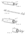
- Fig. 1 is a pictorial view of a first embodiment of flexible hand grips on extended core ends of a roll of plastics stretch film;
- Fig. 2 is an exploded pictorial view of an extended length core for plastics stretch film and flexible hand grips;
- Fig. 3 is a pictorial view of a second embodiment of flexible hand grips on core extensions of a roll of plastics stretch film;
- Fig. 4 is a partial exploded pictorial view of the second embodiment of a flexible hand grip on a core extension of a roll of plastics stretch film.
- Referring to the drawings and particularly to Figs. 1 and 3, a first embodiment of the system for plastics stretch film is seen at 10 in Fig. 1, and a second embodiment of the system for plastics stretch fil is seen at 10 in Fig. 3.
- In Fig. 1 a roll of
plastics stretch film 12 is shown on acore 14. The direction of the core wrap of the roll ofplastics stretch film 12 is shown by the arrow thereon, however, it is to be understood that the direction of the arrow on such a drawing could be reversed without changing the concept of this invention. - A pair of cylindrical flexible tube-
like hand grips 16 are shown in Fig. 1 on the ends of saidcore 14 of said roll ofplastics stretch film 12. - The
inside diameter 18 ofhand grips 16 is a close fit over the outside diameter ofcore 14, but with sufficient clearance so that thecore 14 can turn easily witin thehand grip 16. - In Fig. 2 the length of
core 14 can be seen to be in one piece. Thehand grips 16 are shown in an exploded view in relation to thecore 14. Theinside diameter 18 ofhand grip 16 is shown in relation to the outside diameter of thecore 14. - The extension of the
core 14 on each side the roll ofplastics stretch film 12 for a distance on each side thereof that is slightly more.than the length of thehand grip 16 is a part of this first embodiment of this invention. Thus, the extendedlength core 14, or in other words, thecore 14 with extended ends, is an element of this invention. - It is to be noted that a hollow tube-like core is illustrated but it is to be understood that a solid rod-like core is within the scope and intent of this invention.
- It is to be noted that the outside diameter of
core 14 is smaller than the usual or normal diameter of prior art cores of rolls of plastics stretch film. The usual or normal diameter of prior art cores isshown ascore 32 of the roll ofplastics stretch film 22 in Fig. 3, which will be described hereinafter. - It is to be understood that the possible chance existence of a small diameter core for a roll of plastics stretch film in no way precludes the present invention. Cores for rolls of plastics stretch film are normally of a length approximating the width of the plastics stretch film wrapped thereon, and this invention includes the extension of the length of the core to provide extended ends as hereinbefore described for the first embodiment.
- Turning now to the second embodiment of the system for
plastics stretch film 20, the following description relates to Figs. 3 and 4. - The second embodiment of the system for
plastics stretch film 20 provides a means for using rolls ofplastics stretch film 22 oncore 32 where the length of thecore 32 is approximately the same as the width of the roll ofplastics stretch film 22. This second embodiment provides a means cf using the roll ofplastics stretch film 22 on acore 32 without the need for rerolling theplastics stretch film 22 off of a short length core such ascore 32 on to a larger length core such ascore 14 in Figs. 1 and 2. - As noted thereinbefore, the usual or normal outside diameter of
core 32 is larger than the outside diameter ofcore 14 of the first embodiment. - The
second embodiment 20 provides a pair of adapters so thatcore 32 can be used with the same pair ofhand grips 16 that are used in thefirst embodiment 10. In Figs. 3 and 4 thehand grips 16 of thefirst embodiment 10 are shown ashand grips 26 for clarity when speaking of thesecond embodiment 20.Hand grips 16 of thefirst embodiment 10 andhand grips 26 of thesecond embodiment 20 are exactly alike and can be considered one and the same concept. - The aforementioned adapter is shown in Figs. 3 and 4 at 30. It is to be noted that the
adapter 30, one for each hand grip ., may be constructed in two ways. - The first construction:of
adapter 30 is as a single washer-like plug. The outside diameter ofadapter 30 is a very close and tight fit for theinside diameter 34 ofcore 32 of the roll ofplastics stretch film 22. The outside surface ofadapter 30 has a very slight taper in order to introduce it easily into theinside diameter 34 ofcore 32. A short length of core 24 (the size ofcore 24 being exactly the same ascore 14 of the first embodiment as far as the diameter is concerned) is inserted into the inside diameter of the washer-like adapter 30 for a very tight friction hdd fit. This first construction is shown in Figs. 3 and 4. - The second construction of
adapter 30 is as a single piece unit where both theelement 30 and theelement 24 are of one-piece construction, the total being of the same overall configuration as the first construction, but not illustrated on the drawings. In this second construction the shape and taper of theelement 30 for fitting theinside diameter 34 ofcore 32 are exactly the same as described for the first construction hereinbefore. In this second construction, the outside diameter of theelement 24 is exactly the same as described for the first construction hereinbefore. - Hand grips 26 are placed on the adapter element 24 (either first or second construction) the same as hand grips 16 were placed on the extensions of
core 14 in the first embodiment. Theinside diameter 28 of hand grips 26 is a close fit over theoutside diameter element 24, but with sufficient clearance so thatelement 24 can turn easily witin thehand grip 26, the same ascore 14 turns easilywiMn hand grip 16 in the first embodiment. - As to the materials: the
cores adapter 30 may be wood, fiber, plastics or any similar or suitable material for the second construction or combination thereof forelements - In operation, the user grips the hand grips 16 (for first embodiment) or 26 (for second embodiment) on the extension of
core 14 orcore extension 24, respectively, and gives a slight squeeze to the hand grips 16 (or 26) in order to "feel" the extension of core 14 (or core extension 24). In the description of the operation which follows, only thefirst embodiment 10 will be described, the description for thesecond embodiment 20 is exactly the same. - In case where the initial friction between the hand grips 16 or 26 and the
cores - As the operator plays out the
plastics stretch film 12 during the wrapping of a unit or the securing of unit to a transporting means, a sufficient grip is maintained on the hand grips 16 to provide the necessary control of tension on theplastics stretch film 22. This control of tension is gaged by the "feel" of the extension ofcore 14 through the soft flexible hand grips 16. The operator can make a full stop of the turning by a tight squeeze on hand grips 16 or the operator can have a free running play out of plastics stretchfilm 12 as the plastics stretch film unrolls by loosening the squeeze on hand grips 16. Varying of hand squeeze pressure on hand grips 16 permits the control of the play out of plastics stretchfilm 12 while also controlling how tightly theplastics stretch film 12 is pulled to provide the wrap or securing of the unit being packaged or secured. The squeezing of the hand grips 16 provides a bracking action that has controlled instantaneous results. - The use of this system may be practiced by a manufacturer involving the plastics stretch film on cores as illustrated in this invention, or by a user rewinding the film on a core of his choos--ing from a supply unit.
- As can be readily understood from the foregoing description of the invention, the present structure and system can be configured or operated in different modes or ways to provide the ability to use plastics stretch film to package a unit or to secure a unit to a transporting means.
- Accordingly, modifications and variations to which the invention is susceptible may be practiced without departing from the scope and intent of the appended claims.
Claims (11)
Priority Applications (2)
| Application Number | Priority Date | Filing Date | Title |
|---|---|---|---|
| AT79200780T ATE13847T1 (en) | 1979-12-18 | 1979-12-18 | DEVICE FOR MANUAL APPLICATION OF PLASTIC STRETCH FILM. |
| EP79200780A EP0030572B1 (en) | 1979-12-18 | 1979-12-18 | Apparatus for manually applying plastics stretch films |
Applications Claiming Priority (1)
| Application Number | Priority Date | Filing Date | Title |
|---|---|---|---|
| EP79200780A EP0030572B1 (en) | 1979-12-18 | 1979-12-18 | Apparatus for manually applying plastics stretch films |
Publications (2)
| Publication Number | Publication Date |
|---|---|
| EP0030572A1 true EP0030572A1 (en) | 1981-06-24 |
| EP0030572B1 EP0030572B1 (en) | 1985-06-19 |
Family
ID=8186310
Family Applications (1)
| Application Number | Title | Priority Date | Filing Date |
|---|---|---|---|
| EP79200780A Expired EP0030572B1 (en) | 1979-12-18 | 1979-12-18 | Apparatus for manually applying plastics stretch films |
Country Status (2)
| Country | Link |
|---|---|
| EP (1) | EP0030572B1 (en) |
| AT (1) | ATE13847T1 (en) |
Cited By (10)
| Publication number | Priority date | Publication date | Assignee | Title |
|---|---|---|---|---|
| EP0121860A1 (en) * | 1983-03-29 | 1984-10-17 | Joseph Goldstein | Improved stretch-wrap film dispenser |
| EP0200662A1 (en) * | 1985-07-03 | 1986-11-05 | Sopalplast S.A. | Device for unwinding rolls of film material |
| US9272870B2 (en) | 2013-12-17 | 2016-03-01 | Pratt Corrugated Holdings, Inc. | Braking wrap dispenser |
| US9908656B2 (en) | 2015-01-30 | 2018-03-06 | Pratt Corrugated Holdings, Inc. | Capped wrap dispenser |
| US9988171B2 (en) | 2015-03-10 | 2018-06-05 | Pratt Corrugated Holdings, Inc. | Collared wrap dispenser |
| USD832899S1 (en) | 2017-03-09 | 2018-11-06 | Pratt Corrugated Holdings, Inc. | Braking film dispenser with lobes |
| US10150639B2 (en) | 2016-07-20 | 2018-12-11 | Pratt Corrugated Holdings, Inc. | Wrap dispenser with flat rim cap |
| US10287122B2 (en) | 2017-03-09 | 2019-05-14 | Pratt Corrugated Holdings, Inc. | Braking film dispenser with lobes |
| US11203509B2 (en) | 2019-11-15 | 2021-12-21 | Pratt Corrugated Holdings, Inc. | Wrap dispenser |
| USD983555S1 (en) | 2019-11-15 | 2023-04-18 | Pratt Corrugated Holdings, Inc. | Wrap dispenser with ribbed core |
Citations (2)
| Publication number | Priority date | Publication date | Assignee | Title |
|---|---|---|---|---|
| US4102513A (en) * | 1977-09-14 | 1978-07-25 | Twyman Guard | Film wrapping dispenser |
| US4166589A (en) * | 1978-03-24 | 1979-09-04 | George J. Reid | Portable wrapping film dispenser |
-
1979
- 1979-12-18 AT AT79200780T patent/ATE13847T1/en not_active IP Right Cessation
- 1979-12-18 EP EP79200780A patent/EP0030572B1/en not_active Expired
Patent Citations (2)
| Publication number | Priority date | Publication date | Assignee | Title |
|---|---|---|---|---|
| US4102513A (en) * | 1977-09-14 | 1978-07-25 | Twyman Guard | Film wrapping dispenser |
| US4166589A (en) * | 1978-03-24 | 1979-09-04 | George J. Reid | Portable wrapping film dispenser |
Cited By (19)
| Publication number | Priority date | Publication date | Assignee | Title |
|---|---|---|---|---|
| EP0121860A1 (en) * | 1983-03-29 | 1984-10-17 | Joseph Goldstein | Improved stretch-wrap film dispenser |
| EP0200662A1 (en) * | 1985-07-03 | 1986-11-05 | Sopalplast S.A. | Device for unwinding rolls of film material |
| FR2584383A1 (en) * | 1985-07-03 | 1987-01-09 | Sopalplast Sa | DEVICE FOR UNWINDING ROLLS OF MATERIALS IN FILMS |
| US10280036B2 (en) | 2013-12-17 | 2019-05-07 | Pratt Corrugated Holdings, Inc. | Braking wrap dispenser |
| US9272870B2 (en) | 2013-12-17 | 2016-03-01 | Pratt Corrugated Holdings, Inc. | Braking wrap dispenser |
| US9688507B2 (en) | 2013-12-17 | 2017-06-27 | Pratt Corrugated Holdings, Inc. | Braking wrap dispenser |
| US9950896B2 (en) | 2013-12-17 | 2018-04-24 | Pratt Corrugated Holdings, Inc. | Braking wrap dispenser |
| US9908656B2 (en) | 2015-01-30 | 2018-03-06 | Pratt Corrugated Holdings, Inc. | Capped wrap dispenser |
| US9988171B2 (en) | 2015-03-10 | 2018-06-05 | Pratt Corrugated Holdings, Inc. | Collared wrap dispenser |
| US10494213B2 (en) | 2016-07-20 | 2019-12-03 | Pratt Corrugated Holdings, Inc. | Wrap dispenser with flat rim cap |
| US10150639B2 (en) | 2016-07-20 | 2018-12-11 | Pratt Corrugated Holdings, Inc. | Wrap dispenser with flat rim cap |
| US10287122B2 (en) | 2017-03-09 | 2019-05-14 | Pratt Corrugated Holdings, Inc. | Braking film dispenser with lobes |
| USD832899S1 (en) | 2017-03-09 | 2018-11-06 | Pratt Corrugated Holdings, Inc. | Braking film dispenser with lobes |
| US11040845B2 (en) | 2017-03-09 | 2021-06-22 | Pratt Corrugated Holdings, Inc. | Braking film dispenser with lobes |
| US11203509B2 (en) | 2019-11-15 | 2021-12-21 | Pratt Corrugated Holdings, Inc. | Wrap dispenser |
| US11584610B2 (en) | 2019-11-15 | 2023-02-21 | Pratt Corrugated Holdings, Inc. | Rotating member for wrap dispenser |
| US11591180B2 (en) | 2019-11-15 | 2023-02-28 | Pratt Corrugated Holdings, Inc. | Wrap dispenser |
| USD983555S1 (en) | 2019-11-15 | 2023-04-18 | Pratt Corrugated Holdings, Inc. | Wrap dispenser with ribbed core |
| US11814261B2 (en) | 2019-11-15 | 2023-11-14 | Pratt Corrugated Holdings, Inc. | Wrap dispenser |
Also Published As
| Publication number | Publication date |
|---|---|
| ATE13847T1 (en) | 1985-07-15 |
| EP0030572B1 (en) | 1985-06-19 |
Similar Documents
| Publication | Publication Date | Title |
|---|---|---|
| US4179081A (en) | Apparatus for application of plastics stretch films | |
| US4248392A (en) | Apparatus for application of plastics stretch films | |
| US4834312A (en) | Tool for manually dispensing a web | |
| US4600163A (en) | Apparatus for controlled manual unrolling of rolled flexible material | |
| US4530473A (en) | Apparatus for application of plastics stretch films | |
| US4034926A (en) | Gauze dispenser | |
| EP0030572A1 (en) | Apparatus for manually applying plastics stretch films | |
| US5094395A (en) | Apparatus and method for dispensing plastic stretch film | |
| US4784348A (en) | Dispenser and method for applying web-like material to packaging units | |
| US5351905A (en) | Cohesive stretch-tape wrapper with positive-braking action | |
| US20180065827A1 (en) | Rolled material dispenser | |
| US4117988A (en) | Reel adapter for tie material and method of using the same | |
| RU2070858C1 (en) | Device for delivering packing material roll | |
| US4630786A (en) | Apparatus for dispensing plastics stretch film | |
| US5639043A (en) | Despooled filament tension control device | |
| GB2299321A (en) | Dispensing of packaging film from a roll | |
| US20010032904A1 (en) | Holders for a roll core | |
| US5121885A (en) | Sheet fabric slitter and reroller | |
| EP0156468B1 (en) | Apparatus for dispensing plastics stretch film | |
| US3035395A (en) | Wire wrapping machine | |
| EP0300695A2 (en) | Sheet material handling system, and dispenser and winding apparatus for use therein | |
| US3057578A (en) | Tension control device | |
| US3021094A (en) | Strand dispensing and binding tool | |
| US3827653A (en) | Thread dispensing bobbin | |
| GB2192611A (en) | A device for dispensing a material |
Legal Events
| Date | Code | Title | Description |
|---|---|---|---|
| PUAI | Public reference made under article 153(3) epc to a published international application that has entered the european phase |
Free format text: ORIGINAL CODE: 0009012 |
|
| AK | Designated contracting states |
Designated state(s): AT BE CH FR IT LU NL SE |
|
| 17P | Request for examination filed |
Effective date: 19810518 |
|
| ITF | It: translation for a ep patent filed |
Owner name: STUDIO TORTA SOCIETA' SEMPLICE |
|
| GRAA | (expected) grant |
Free format text: ORIGINAL CODE: 0009210 |
|
| AK | Designated contracting states |
Designated state(s): AT BE CH FR IT LU NL SE |
|
| REF | Corresponds to: |
Ref document number: 13847 Country of ref document: AT Date of ref document: 19850715 Kind code of ref document: T |
|
| ET | Fr: translation filed | ||
| PG25 | Lapsed in a contracting state [announced via postgrant information from national office to epo] |
Ref country code: LU Free format text: LAPSE BECAUSE OF NON-PAYMENT OF DUE FEES Effective date: 19851231 |
|
| PLBE | No opposition filed within time limit |
Free format text: ORIGINAL CODE: 0009261 |
|
| STAA | Information on the status of an ep patent application or granted ep patent |
Free format text: STATUS: NO OPPOSITION FILED WITHIN TIME LIMIT |
|
| 26N | No opposition filed | ||
| ITTA | It: last paid annual fee | ||
| PGFP | Annual fee paid to national office [announced via postgrant information from national office to epo] |
Ref country code: SE Payment date: 19911209 Year of fee payment: 13 |
|
| PGFP | Annual fee paid to national office [announced via postgrant information from national office to epo] |
Ref country code: FR Payment date: 19921209 Year of fee payment: 14 |
|
| PGFP | Annual fee paid to national office [announced via postgrant information from national office to epo] |
Ref country code: AT Payment date: 19921211 Year of fee payment: 14 |
|
| PG25 | Lapsed in a contracting state [announced via postgrant information from national office to epo] |
Ref country code: SE Effective date: 19921219 |
|
| PGFP | Annual fee paid to national office [announced via postgrant information from national office to epo] |
Ref country code: CH Payment date: 19921223 Year of fee payment: 14 |
|
| PGFP | Annual fee paid to national office [announced via postgrant information from national office to epo] |
Ref country code: BE Payment date: 19930127 Year of fee payment: 14 |
|
| PG25 | Lapsed in a contracting state [announced via postgrant information from national office to epo] |
Ref country code: AT Effective date: 19931218 |
|
| PG25 | Lapsed in a contracting state [announced via postgrant information from national office to epo] |
Ref country code: CH Effective date: 19931231 Ref country code: BE Effective date: 19931231 |
|
| BERE | Be: lapsed |
Owner name: PARRY JOHN CHARLES Effective date: 19931231 |
|
| PG25 | Lapsed in a contracting state [announced via postgrant information from national office to epo] |
Ref country code: FR Effective date: 19940831 |
|
| REG | Reference to a national code |
Ref country code: CH Ref legal event code: PL |
|
| REG | Reference to a national code |
Ref country code: FR Ref legal event code: ST |
|
| EUG | Se: european patent has lapsed |
Ref document number: 79200780.9 Effective date: 19930709 |
|
| PGFP | Annual fee paid to national office [announced via postgrant information from national office to epo] |
Ref country code: NL Payment date: 19981231 Year of fee payment: 20 |
|
| PG25 | Lapsed in a contracting state [announced via postgrant information from national office to epo] |
Ref country code: NL Free format text: LAPSE BECAUSE OF EXPIRATION OF PROTECTION Effective date: 19991218 |
|
| NLV7 | Nl: ceased due to reaching the maximum lifetime of a patent |
Effective date: 19991218 |