EP0029361B1 - Liquid sample collector device - Google Patents
Liquid sample collector device Download PDFInfo
- Publication number
- EP0029361B1 EP0029361B1 EP80304103A EP80304103A EP0029361B1 EP 0029361 B1 EP0029361 B1 EP 0029361B1 EP 80304103 A EP80304103 A EP 80304103A EP 80304103 A EP80304103 A EP 80304103A EP 0029361 B1 EP0029361 B1 EP 0029361B1
- Authority
- EP
- European Patent Office
- Prior art keywords
- vessel
- plug
- cap
- spigot
- aperture
- Prior art date
- Legal status (The legal status is an assumption and is not a legal conclusion. Google has not performed a legal analysis and makes no representation as to the accuracy of the status listed.)
- Expired
Links
- 239000007788 liquid Substances 0.000 title claims abstract description 36
- 230000015572 biosynthetic process Effects 0.000 claims abstract description 22
- 238000005755 formation reaction Methods 0.000 claims description 20
- 125000006850 spacer group Chemical group 0.000 claims description 12
- 238000012546 transfer Methods 0.000 claims description 8
- 239000008280 blood Substances 0.000 abstract description 35
- 210000004369 blood Anatomy 0.000 abstract description 35
- 238000011109 contamination Methods 0.000 abstract description 3
- 239000003085 diluting agent Substances 0.000 description 10
- 239000000463 material Substances 0.000 description 6
- 239000004033 plastic Substances 0.000 description 3
- 229920003023 plastic Polymers 0.000 description 3
- 206010053567 Coagulopathies Diseases 0.000 description 1
- 239000004743 Polypropylene Substances 0.000 description 1
- 239000004793 Polystyrene Substances 0.000 description 1
- 238000013459 approach Methods 0.000 description 1
- 230000035602 clotting Effects 0.000 description 1
- 239000013078 crystal Substances 0.000 description 1
- 230000000994 depressogenic effect Effects 0.000 description 1
- 238000013461 design Methods 0.000 description 1
- 230000006866 deterioration Effects 0.000 description 1
- 230000000694 effects Effects 0.000 description 1
- 239000011521 glass Substances 0.000 description 1
- 229920001903 high density polyethylene Polymers 0.000 description 1
- 239000004700 high-density polyethylene Substances 0.000 description 1
- 238000011835 investigation Methods 0.000 description 1
- 229920001684 low density polyethylene Polymers 0.000 description 1
- 239000004702 low-density polyethylene Substances 0.000 description 1
- 230000013011 mating Effects 0.000 description 1
- 238000000034 method Methods 0.000 description 1
- 238000009629 microbiological culture Methods 0.000 description 1
- 238000012986 modification Methods 0.000 description 1
- 230000004048 modification Effects 0.000 description 1
- 238000000465 moulding Methods 0.000 description 1
- -1 polypropylene Polymers 0.000 description 1
- 229920001155 polypropylene Polymers 0.000 description 1
- 229920002223 polystyrene Polymers 0.000 description 1
- 238000012545 processing Methods 0.000 description 1
- 230000000284 resting effect Effects 0.000 description 1
- 238000005070 sampling Methods 0.000 description 1
- 230000035939 shock Effects 0.000 description 1
- 238000012360 testing method Methods 0.000 description 1
- 238000005406 washing Methods 0.000 description 1
Images
Classifications
-
- B—PERFORMING OPERATIONS; TRANSPORTING
- B01—PHYSICAL OR CHEMICAL PROCESSES OR APPARATUS IN GENERAL
- B01L—CHEMICAL OR PHYSICAL LABORATORY APPARATUS FOR GENERAL USE
- B01L3/00—Containers or dishes for laboratory use, e.g. laboratory glassware; Droppers
- B01L3/50—Containers for the purpose of retaining a material to be analysed, e.g. test tubes
- B01L3/508—Containers for the purpose of retaining a material to be analysed, e.g. test tubes rigid containers not provided for above
- B01L3/5082—Test tubes per se
Definitions
- This invention relates to a collector device for receiving, metering and holding a sample of liquid of predetermined small volume, comprising a collection vessel having an aperture leading into its interior and a plug.
- the invention is particularly although not exclusively applicable to the collection of samples of human blood drawn directly from patients and required for subsequent laboratory analysis of investigation.
- a sample of capillary blood may be taken from a drop of blood obtained by pricking a patient's finger.
- One object of the present invention is to provide a collector device which enables a sample of blood from such a blood drop to be transferred in a metered quantity into a collection vessel forming part of the device, without the need for using a capillary tube to meter the sample.
- Such capillary tubes are inherently fragile and require careful and delicate handling, and can be difficult to empty completely, and the avoidance of their use will greatly facilitate the transfer of the blood sample from the patient's finger into the diluent-containing collection vessel.
- the invention may however be used for the collection of metered samples of any liquid which is required to be provided in small quantities for analysis or testing, for example samples of microbial cultures.
- a collector device for receiving, metering and holding a sample of liquid of predetermined small volume, comprises a collection vessel having an aperture leading into its interior, a plug which is a push-fit in the aperture and closes the vessel when inserted in the aperture prior to use of the device, the plug being capable of being pushed slidably through the aperture to enter the interior of the vessel, and a co-operating spigot member capable of being inserted into the aperture as a close fit therein, the opposed ends of the plug and spigot member being formed with co-operating formations shaped to define between them, when the said ends of the spigot and plug are abutted, a space of predetermined volume by which in use a sample of the liquid can be metered and temporarily trapped therein, whereby in use the spigot member can be advanced inwardly through the aperture in abutment with the plug to push the plug ahead of it and displace the plug from the aperture into the interior of the vessel so as to transfer the trapped metered liquid sample into the
- the spigot member may for example be carried by a cap having a screwthread which fits a cooperating screwthread on the vessel, whereby the cap can be screwed down on to the vessel to advance the spigot through the throat and display the plug into the interior of the vessel.
- the cooperating ends of the plug and spigot may be formed in various ways to define the space of predetermined volume between them on abutment, but in a preferred arrangement the opposed ends of the plug and spigot have co- operating concave and convex formations adapted, when the opposed ends are abutted together, to define between them a closed space of predetermined volume less than the volume of the concave formation whereby, when the opposed ends are brought together with the concave formation filled with liquid, excess liquid will be displaced from the concave formation by the convex formation leaving a metered volume of the liquid trapped in the closed space between the abutted spigot and plug.
- the outer end of the plug may be formed with an outwardly-facing cup-shaped recess
- the cooperating end of the spigot may include an axially-projecting portion, e.g. of conical or other tapering form, which enters the recess in the plug to displace excess liquid therefrom as the spigot moves into abutment with the plug.
- the plug and the spigot end may have circumferential shoulders respectively surrounding the recess and projecting portion, which shoulders form the abutting surfaces of the plug and spigot.
- an excess volume of the liquid being sampled e.g. blood can be introduced into the recess in the plug to fill the recess.
- the spigot will then be introduced into the aperture of the vessel and as it approaches the plug its projecting portion will enter the recess and displace excess sample liquid therefrom until the spigot abuts the plug, leaving the space defined between their ends filled with the predetermined volume of sample liquid.
- the spigot is then pushed through the throat to displace the plug the liquid sample of predetermined metered volume will thereby be transferred into the interior of the vessel, which may already contain a diluent liquid.
- the invention is applied to a collector device for receiving and holding a small metered quantity of sample liquid, for example blood obtained from a patient.
- the device comprises a collection vessel 10 whose top 11, shown in this case as a separate component pushfitted onto the upper rim of the vessel, provides a neck 12 having an external screwthread 13 and a coaxial cylindrical bore 14.
- the top portion 11 could however be integral with or bonded to the vessel 10, which is made of glass, rigid or semirigid plastics material or any other suitable material.
- a cap 15 with a co-operating internal screwthread can be screwed onto the neck 12 and in its fully-screwed-down position shown in Figure 4 its lower edge will abut against a co- operating shoulder on the top member 11.
- the cap can be prevented from being screwed down beyond a raised position, shown in Figure 1, by a removable spacer washer 16, and/or by a removable space disc 17 positioned inside the cap 15.
- a cup-shaped or tubular spacer member could be employed resting on the neck 12 with its wall extending up towards the top of the cap.
- the neck 12 of the top 11 of the collection vessel is provided with an inturned circumferential flange at the upper end of its bore 14, the flange defining a cylindrical throat 20 leading into the interior of the vessel 10 and having a mouth at its outer end.
- a small cylindrical plug 22 is located as a push-fit in the throat 20 so as to close the vessel 10 and retain therein a measured quantity of diluent liquid 23.
- the plug has an open-topped upwardly-facing recess 24 formed in its upper end, the recess 24 being of smoothly-curved form, e.g. part-spherical, and of depth such that it is slightly less than a hemisphere.
- the recess 24 is surrounded by an annular shoulder 25 ( Figure 3) forming the circumferential margin of the top of the plug.
- the plug can be so positioned in the throat 20 that its marginal shoulder 25 is flush with the top of the neck 12.
- the cap 15 is formed with a central coaxial cylindrical spigot 30 which is formed at its free end with a tapering, e.g. conical, forwardly-projecting portion 31, surrounded by an annular shoulder 32.
- the diameter of the spigot 30 is such that it can enter the throat 20 of the neck 12 as a close sliding fit, pushing the plug 22 downwardly, when the cap is screwed down beyond its raised position of Figure 1.
- the base diameter of the tapering portion 31 of the spigot matches exactly that of the mouth of the recess 24 in the plug but its axial height is less than the depth of the recess 24.
- the sides of both the recess 24 in the plug 22 and the projecting tapered portion 31 of the spigot 30 are reproducibly formed, e.g.
- the cap 1 is now screwed down further to cause the spigot 30 to push the plug 22 down along the throat 20 as the spigot 30 enters the throat as a close fit therein.
- the plug 22 will be pushed out of the throat 20 and will fall into the interior of the vessel 10, and the trapped blood sample, of predetermined known volume, will be released within the vessel.
- the spigot self-seals the throat 20 in place of the plug 22, thus retaining the liquid in the container and preventing any excess blood which was displaced from the recess 24 by the protruding end of the spigot from entering the vessel via its throat.
- the plug 22 is preferably made of a material of greater density than the diluent 23, so that it will sink readily in the diluent allowing the blood contents of the recess 24 to be dispersed in the diluent. This dispersal can be aided by shaking the vessel 10 manually, which also applies the diluent to the end of the spigot in the throat 20, washing away any part of the blood sample which remains on the spigot.
- the collector device can be sent to the laboratory for processing, or to storage. Subsequent analysis of the blood sample in the diluent can be performed after the vessel has been opened by removing the top portion 11 and cap 15 as a whole where the top portion 11 is a separate component, or by some other method of direct entry to the vessel 10, e.g. by cutting off the base or by piercing with a sampling needle, if the top 11 is integral with or bonded to the vessel 10.
- the container 10 may be of such a design as to fit directly into currently-available auto-analysers or other assaying equipment, without need for the transfer of the liquid contents from the container.
- cap 1 The application of the cap 1 to the threaded neck after a blood sample has been transferred into the recess 24 ensures that the outer end of the neck, which may be contaminated with blood, will be enclosed by the cap and there is little chance of inadvertent contamination of the exterior of the closed collector device or of the transfer of contamination to personnel handling the closed device.
- the centre of the disc may be formed with a hole or depression, so that the pointed tip will not contact it. If a cup-shaped spacer is employed instead of the disc, its base may be similarly apertured or depressed.
- Figures 5 to 7 show a second embodiment of the invention in which the collection vessel has a main body portion 1 OA of circular section and a cap 15A which is of larger diameter than the cap 15 and has an internal screwthread 50A.
- the cap 15A is screwed onto a screwthread 51 A which is formed on the exterior of the cylindrical upper part of the main body portion 10A.
- the lower part of the main body portion 10A has a slight taper.
- the top of the collection vessel comprises a circular closure insert 52A which is a tight push fit in the upper end of the main body portion 10A and has a locating flange 53A which overlies the edge of the wall of the body portion 10A and limits the extent to which the closure insert can be pushed into the main body portion, as indicated in Figures 5 and 6.
- the cap 15A carries an integral spigot 30A similar to the spigot 30, which co-operates with a plug 22A similar to the plug 30 in the same manner as described above in relation to the spigot 30 and plug 22 of Figures 1 to 4.
- closure insert 52A is not formed with a protruding neck, but has a central circular hole 20A defined by a flange 54A, in which hole the plug 22A is a push-fit.
- the closure insert 52A also has an axially projecting annular flange 55A near its outer circumference which is directed away from the main body portion 10A (when the insert 52A is in position in the main body portion 10A).
- This flange 55A has an integral annular latch formation 57A on its outer circumference, which, when the cap 15A is fully screwed down on the main body portion 10A, comes into latching engagement behind a co- operating annular abutment surface 58A formed by one side of an internal circumferential groove 59A in the interior of the cap 1 5A.
- the insert 52A is made of a suitable plastics material which is sufficiently resilient to allow the flange 55A to yield inwardly and then snap outwardly into latching engagement in the groove 59A in the manner of a bayonet catch.
- Figures 6 and 7 show the cap and closure insert interengaged in this manner.
- the device illustrated in Figures 5 to 7 is employed in much the same way as that of Figures 1 to 4.
- the device is supplied with a spacer disc 17A interposed between the spigot 30A and the closure insert 52A to locate the cap in its partially-screwed-down position.
- the spacer disc 17A is removed, a blood sample is introduced into the cup formation in the plug 22A, and the cap 1 5A is screwed down on the main body portion 10A of the vessel to trap a metered volume of blood in the space defined between the co-operating formations of the spigot and plug, as previously described. Further screwing down of the cap 15A will cause the spigot to enter the hole 20A and force the plug 22A out of the hole and into the interior of the vessel, thus releasing the metered blood sample into the diluent 23A in the vessel.
- the latching flange 55A will yield resiliently as it is forced into the. restricted interior of the cup until it snaps into latching engagement in the groove 59A, when the engagement of the latch formation 57A behind the groove abutment 58A will latch the closure insert 57A positively to the cap 15A.
- the closed vessel containing the metered blood sample can now be despatched to the laboratory for subsequent analysis.
- the cap can be gently unscrewed from the main body portion 10A and will slowly withdraw the closure insert 52A, which is latched to it by the connection 57A, 58A, axially from the main body portion 1 OA thus opening the vessel to give access to its interior.
- the slow and gentle withdrawal of the closure insert 52A enables the vessel to be opened without any sudden shock or snap effect and avoids any risk of droplets of the liquid contents being dissipated into the surrounding atmosphere in the laboratory as a potential hazard to personnel.
- the components of the device shown in Figures 5 to 7 may be made of various materials, but the following preferred plastics materials are given by way of example:
- a modified form of the plug, 22 or 22A the modification consisting of an integral locating formation, for example a thin radially-projecting circumferential flange around the side of the plug, which will overlie the top of the neck 12 or insert 52A as the case may be to locate the plug in its initial inserted position of Figure 1 or 5 respectively.
- an integral locating formation for example a thin radially-projecting circumferential flange around the side of the plug, which will overlie the top of the neck 12 or insert 52A as the case may be to locate the plug in its initial inserted position of Figure 1 or 5 respectively.
Abstract
Description
- This invention relates to a collector device for receiving, metering and holding a sample of liquid of predetermined small volume, comprising a collection vessel having an aperture leading into its interior and a plug.
- The invention is particularly although not exclusively applicable to the collection of samples of human blood drawn directly from patients and required for subsequent laboratory analysis of investigation. For example, a sample of capillary blood may be taken from a drop of blood obtained by pricking a patient's finger.
- It is standard practice in clinical work to transfer blood from such a drop into a fine capillary tube, which when filled thus contains a metered sample of fresh blood whose quantity is determined by the length and bore of the capillary tube. The blood sample is then transferred into a collection vessel containing a diluent which prevents clotting and deterioration of the blood sample, and the vessel can be closed and despatched to the laboratory for analysis.
- One object of the present invention is to provide a collector device which enables a sample of blood from such a blood drop to be transferred in a metered quantity into a collection vessel forming part of the device, without the need for using a capillary tube to meter the sample. Such capillary tubes are inherently fragile and require careful and delicate handling, and can be difficult to empty completely, and the avoidance of their use will greatly facilitate the transfer of the blood sample from the patient's finger into the diluent-containing collection vessel.
- The invention may however be used for the collection of metered samples of any liquid which is required to be provided in small quantities for analysis or testing, for example samples of microbial cultures.
- Acording to the present invention, a collector device for receiving, metering and holding a sample of liquid of predetermined small volume, comprises a collection vessel having an aperture leading into its interior, a plug which is a push-fit in the aperture and closes the vessel when inserted in the aperture prior to use of the device, the plug being capable of being pushed slidably through the aperture to enter the interior of the vessel, and a co-operating spigot member capable of being inserted into the aperture as a close fit therein, the opposed ends of the plug and spigot member being formed with co-operating formations shaped to define between them, when the said ends of the spigot and plug are abutted, a space of predetermined volume by which in use a sample of the liquid can be metered and temporarily trapped therein, whereby in use the spigot member can be advanced inwardly through the aperture in abutment with the plug to push the plug ahead of it and displace the plug from the aperture into the interior of the vessel so as to transfer the trapped metered liquid sample into the interior of the vessel, the spigot member when so advanced fitting closely within the aperture so as to close the vessel.
- The spigot member may for example be carried by a cap having a screwthread which fits a cooperating screwthread on the vessel, whereby the cap can be screwed down on to the vessel to advance the spigot through the throat and display the plug into the interior of the vessel.
- The cooperating ends of the plug and spigot may be formed in various ways to define the space of predetermined volume between them on abutment, but in a preferred arrangement the opposed ends of the plug and spigot have co- operating concave and convex formations adapted, when the opposed ends are abutted together, to define between them a closed space of predetermined volume less than the volume of the concave formation whereby, when the opposed ends are brought together with the concave formation filled with liquid, excess liquid will be displaced from the concave formation by the convex formation leaving a metered volume of the liquid trapped in the closed space between the abutted spigot and plug. For example, the outer end of the plug may be formed with an outwardly-facing cup-shaped recess, and the cooperating end of the spigot may include an axially-projecting portion, e.g. of conical or other tapering form, which enters the recess in the plug to displace excess liquid therefrom as the spigot moves into abutment with the plug. The plug and the spigot end may have circumferential shoulders respectively surrounding the recess and projecting portion, which shoulders form the abutting surfaces of the plug and spigot.
- With such an arrangement, with the spigot removed an excess volume of the liquid being sampled, e.g. blood can be introduced into the recess in the plug to fill the recess. The spigot will then be introduced into the aperture of the vessel and as it approaches the plug its projecting portion will enter the recess and displace excess sample liquid therefrom until the spigot abuts the plug, leaving the space defined between their ends filled with the predetermined volume of sample liquid. When the spigot is then pushed through the throat to displace the plug the liquid sample of predetermined metered volume will thereby be transferred into the interior of the vessel, which may already contain a diluent liquid.
- It would however also be possible to form the recess in the end of the spigot, and the projecting portion on the outer end of the plug. In that case, in use the excess quantity of sample liquid would be placed in the recess, the spigot being held with the recess facing upwards, and the inverted bottle would then be applied to the spigot.
- The invention may be carried into practice in various ways, but one specific embodiment thereof will now be described by way of example only and with reference to the accompanying drawings, in which:
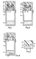
- Figure 1 is a sectional elevation of a liquid sample collector, shown prior to use with its cap in its raised position;
- Figure 2 shows the device of Figure 1 with the cap partly screwed down and in abutment with a plug in the container throat;
- Figure 3 is a detailed view of the abutted end of the cap spigot and the plug;
- Figure 4 is a view similar to Figure 2 but with the cap screwed fully down and the plug displaced into the vessel;
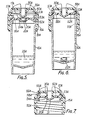
- Figures 5 and 6 are views similar to Figures 1 and 4 respectively of a modified embodiment of the invention in which the cap is crewed onto an external screwthread on the main body of the collection vessel, and
- Figure 7 is a sectional view of the interengaged cap and vessel closure insert of the embodiment of Figures 5 and 6, shown detached from the main body of the vessel.
- In the embodiment shown in Figures 1 to 4 the invention is applied to a collector device for receiving and holding a small metered quantity of sample liquid, for example blood obtained from a patient. The device comprises a
collection vessel 10 whosetop 11, shown in this case as a separate component pushfitted onto the upper rim of the vessel, provides aneck 12 having anexternal screwthread 13 and a coaxialcylindrical bore 14. Thetop portion 11 could however be integral with or bonded to thevessel 10, which is made of glass, rigid or semirigid plastics material or any other suitable material. Acap 15 with a co-operating internal screwthread can be screwed onto theneck 12 and in its fully-screwed-down position shown in Figure 4 its lower edge will abut against a co- operating shoulder on thetop member 11. However, the cap can be prevented from being screwed down beyond a raised position, shown in Figure 1, by aremovable spacer washer 16, and/or by aremovable space disc 17 positioned inside thecap 15. Instead of thedisc 17, a cup-shaped or tubular spacer member could be employed resting on theneck 12 with its wall extending up towards the top of the cap. - The
neck 12 of thetop 11 of the collection vessel is provided with an inturned circumferential flange at the upper end of itsbore 14, the flange defining acylindrical throat 20 leading into the interior of thevessel 10 and having a mouth at its outer end. A smallcylindrical plug 22 is located as a push-fit in thethroat 20 so as to close thevessel 10 and retain therein a measured quantity ofdiluent liquid 23. The plug has an open-topped upwardly-facingrecess 24 formed in its upper end, the recess 24 being of smoothly-curved form, e.g. part-spherical, and of depth such that it is slightly less than a hemisphere. Therecess 24 is surrounded by an annular shoulder 25 (Figure 3) forming the circumferential margin of the top of the plug. The plug can be so positioned in thethroat 20 that itsmarginal shoulder 25 is flush with the top of theneck 12. - The
cap 15 is formed with a central coaxialcylindrical spigot 30 which is formed at its free end with a tapering, e.g. conical, forwardly-projectingportion 31, surrounded by anannular shoulder 32. The diameter of thespigot 30 is such that it can enter thethroat 20 of theneck 12 as a close sliding fit, pushing theplug 22 downwardly, when the cap is screwed down beyond its raised position of Figure 1. The base diameter of the taperingportion 31 of the spigot matches exactly that of the mouth of therecess 24 in the plug but its axial height is less than the depth of therecess 24. The sides of both therecess 24 in theplug 22 and the projectingtapered portion 31 of thespigot 30 are reproducibly formed, e.g. by moulding, so that when theshoulders spigot 30 on screwing down of thecap 15, thespace 35 so defined between the spigot and the plug has a predetermined (and repeatedly reproducible) volume corresponding to the metering volume required for the blood or other liquid sample to be collected. - The use of the device shown in Figures 1 to 4 will now be described in relation to the collection of a metered sample of capillary blood from a blood drop formed by pricking a patient's finger. The device is supplied in the condition shown in Figure 1, and to bring it into use the cap is first unscrewed and the
spacer washer 16 and/or thedisc 17 is/are removed. A quantity of blood from the newly-drawn blood spot is then introduced into therecess 24 in theplug 22 so as to fill the recess completely. This can be done most conveniently by simply applying the patient's finger to the top of the plug so as to transfer the blood into the recess, although if preferred a transfer device such as a liquid dropper could be used. With thevessel 10 held vertical thecap 15 is then replaced and screwed down on theneck 12. As thespigot 30 is coaxial with the screwthreads and hence with thethroat 20 and recess 24, the descent of the spigot will cause its tapering projectingportion 31 to enter therecess 24 and displace excess blood from the recess until theshoulders space 35 of predetermined volume, less than the volume of therecess 24, between theabutted spigot 30 and plug 22. The near-hemispherical shape of therecess 24 reduces any risk of air pockets or bubbles in the liquid initially filling the recess, which might remain in the closedspace 35. The device is now in the condition shown in Figure 2. - The cap 1 is now screwed down further to cause the
spigot 30 to push theplug 22 down along thethroat 20 as thespigot 30 enters the throat as a close fit therein. Eventually theplug 22 will be pushed out of thethroat 20 and will fall into the interior of thevessel 10, and the trapped blood sample, of predetermined known volume, will be released within the vessel. At this stage the spigot self-seals thethroat 20 in place of theplug 22, thus retaining the liquid in the container and preventing any excess blood which was displaced from therecess 24 by the protruding end of the spigot from entering the vessel via its throat. - The
plug 22 is preferably made of a material of greater density than the diluent 23, so that it will sink readily in the diluent allowing the blood contents of therecess 24 to be dispersed in the diluent. This dispersal can be aided by shaking thevessel 10 manually, which also applies the diluent to the end of the spigot in thethroat 20, washing away any part of the blood sample which remains on the spigot. - With the
cap 15 fully screwed on in the position shown in Figure 4, the collector device can be sent to the laboratory for processing, or to storage. Subsequent analysis of the blood sample in the diluent can be performed after the vessel has been opened by removing thetop portion 11 andcap 15 as a whole where thetop portion 11 is a separate component, or by some other method of direct entry to thevessel 10, e.g. by cutting off the base or by piercing with a sampling needle, if thetop 11 is integral with or bonded to thevessel 10. Thecontainer 10 may be of such a design as to fit directly into currently-available auto-analysers or other assaying equipment, without need for the transfer of the liquid contents from the container. - The application of the cap 1 to the threaded neck after a blood sample has been transferred into the
recess 24 ensures that the outer end of the neck, which may be contaminated with blood, will be enclosed by the cap and there is little chance of inadvertent contamination of the exterior of the closed collector device or of the transfer of contamination to personnel handling the closed device. - In order to protect the tip of the projecting
portion 31 of thespigot 30 from damage in the event of the cap being screwed down too hard whilst thedisc 17 is in position in the cap, the centre of the disc may be formed with a hole or depression, so that the pointed tip will not contact it. If a cup-shaped spacer is employed instead of the disc, its base may be similarly apertured or depressed. - Figures 5 to 7 show a second embodiment of the invention in which the collection vessel has a main body portion 1 OA of circular section and a
cap 15A which is of larger diameter than thecap 15 and has aninternal screwthread 50A. In use thecap 15A is screwed onto ascrewthread 51 A which is formed on the exterior of the cylindrical upper part of themain body portion 10A. The lower part of themain body portion 10A has a slight taper. The top of the collection vessel comprises acircular closure insert 52A which is a tight push fit in the upper end of themain body portion 10A and has a locatingflange 53A which overlies the edge of the wall of thebody portion 10A and limits the extent to which the closure insert can be pushed into the main body portion, as indicated in Figures 5 and 6. Thecap 15A carries anintegral spigot 30A similar to thespigot 30, which co-operates with aplug 22A similar to theplug 30 in the same manner as described above in relation to thespigot 30 andplug 22 of Figures 1 to 4. However the closure insert 52A is not formed with a protruding neck, but has a centralcircular hole 20A defined by aflange 54A, in which hole theplug 22A is a push-fit. The closure insert 52A also has an axially projectingannular flange 55A near its outer circumference which is directed away from themain body portion 10A (when theinsert 52A is in position in themain body portion 10A). Thisflange 55A has an integralannular latch formation 57A on its outer circumference, which, when thecap 15A is fully screwed down on themain body portion 10A, comes into latching engagement behind a co- operatingannular abutment surface 58A formed by one side of an internalcircumferential groove 59A in the interior of the cap 1 5A. Theinsert 52A is made of a suitable plastics material which is sufficiently resilient to allow theflange 55A to yield inwardly and then snap outwardly into latching engagement in thegroove 59A in the manner of a bayonet catch. Figures 6 and 7 show the cap and closure insert interengaged in this manner. - The device illustrated in Figures 5 to 7 is employed in much the same way as that of Figures 1 to 4. Thus the device is supplied with a
spacer disc 17A interposed between thespigot 30A and the closure insert 52A to locate the cap in its partially-screwed-down position. For use the cap is unscrewed, thespacer disc 17A is removed, a blood sample is introduced into the cup formation in theplug 22A, and the cap 1 5A is screwed down on themain body portion 10A of the vessel to trap a metered volume of blood in the space defined between the co-operating formations of the spigot and plug, as previously described. Further screwing down of thecap 15A will cause the spigot to enter thehole 20A and force theplug 22A out of the hole and into the interior of the vessel, thus releasing the metered blood sample into the diluent 23A in the vessel. - Moreover as the cap 1 5A is screwed down towards its limiting position in which a
shoulder 60A on the cap engages theflange 53A of the closure insert, as shown in Figure 6, the latchingflange 55A will yield resiliently as it is forced into the. restricted interior of the cup until it snaps into latching engagement in thegroove 59A, when the engagement of thelatch formation 57A behind thegroove abutment 58A will latch the closure insert 57A positively to thecap 15A. - The closed vessel containing the metered blood sample can now be despatched to the laboratory for subsequent analysis. When it is required to open the collection vessel for analysis, the cap can be gently unscrewed from the
main body portion 10A and will slowly withdraw the closure insert 52A, which is latched to it by theconnection - The
main body 10A of the collection vessel:- crystal polystyrene. - The
screw cap 15A:- high-density polyethylene. - The
closure insert 52A:- polypropylene, in a suitable grade to provide the required snap- latching action between theflange 55A andcap 15A. - The
pug 22A:- low-density polyethylene. - Instead of the
spacer disc 17A, a tubular cylindrical spacer, similar to thespacer 16 in Figure 1, could be used, being interposed between the base of thecap 15A and the closure insert 52A inside theannular latch flange 55A. This tubular spacer would be removed before use of the device. - In either of the embodiments described and illustrated it is possible to use a modified form of the plug, 22 or 22A, the modification consisting of an integral locating formation, for example a thin radially-projecting circumferential flange around the side of the plug, which will overlie the top of the
neck 12 or insert 52A as the case may be to locate the plug in its initial inserted position of Figure 1 or 5 respectively. When the cap is screwed down further, causing the spigot to force the plug downwardly towards the interior of the vessel, this locating formation on the plug breaks off to allow the plug to pass through thethroat 20 orholes 20A.
Claims (12)
Priority Applications (1)
| Application Number | Priority Date | Filing Date | Title |
|---|---|---|---|
| AT80304103T ATE9185T1 (en) | 1979-11-19 | 1980-11-14 | LIQUID SAMPLER. |
Applications Claiming Priority (2)
| Application Number | Priority Date | Filing Date | Title |
|---|---|---|---|
| GB7939887 | 1979-11-19 | ||
| GB7939887 | 1979-11-19 |
Publications (3)
| Publication Number | Publication Date |
|---|---|
| EP0029361A2 EP0029361A2 (en) | 1981-05-27 |
| EP0029361A3 EP0029361A3 (en) | 1982-01-27 |
| EP0029361B1 true EP0029361B1 (en) | 1984-08-29 |
Family
ID=10509284
Family Applications (1)
| Application Number | Title | Priority Date | Filing Date |
|---|---|---|---|
| EP80304103A Expired EP0029361B1 (en) | 1979-11-19 | 1980-11-14 | Liquid sample collector device |
Country Status (12)
| Country | Link |
|---|---|
| US (1) | US4346613A (en) |
| EP (1) | EP0029361B1 (en) |
| JP (1) | JPS5693030A (en) |
| AT (1) | ATE9185T1 (en) |
| AU (1) | AU542965B2 (en) |
| BR (1) | BR8007514A (en) |
| DE (1) | DE3069078D1 (en) |
| DK (1) | DK152629C (en) |
| GB (1) | GB2063820B (en) |
| IE (1) | IE50543B1 (en) |
| MX (1) | MX152529A (en) |
| SU (1) | SU1272967A3 (en) |
Cited By (1)
| Publication number | Priority date | Publication date | Assignee | Title |
|---|---|---|---|---|
| CN108566944A (en) * | 2017-03-07 | 2018-09-25 | 翔宇生医科技股份有限公司 | Cell storage container |
Families Citing this family (9)
| Publication number | Priority date | Publication date | Assignee | Title |
|---|---|---|---|---|
| US4787971A (en) * | 1987-01-23 | 1988-11-29 | Alan Donald | Miniaturized column chromatography separation apparatus and method of assaying biomolecules employing the same |
| IT220069Z2 (en) * | 1990-07-27 | 1993-06-09 | Erba Carlo Spa | "VIAL FOR CHEMICAL REAGENTS" |
| GB9114265D0 (en) * | 1991-07-02 | 1991-08-21 | Amersham Int Plc | Sampling device |
| US5442970A (en) * | 1994-06-23 | 1995-08-22 | Hutchins; Charles D. | Water sampling device |
| US8904886B1 (en) * | 1996-08-22 | 2014-12-09 | A+ Manufacturing LLC | Devices for obtaining cylinder samples of natural gas or process gas and methods therefore |
| US6796194B1 (en) | 2001-10-09 | 2004-09-28 | San Diego State University | Liquid sampling device |
| US7883421B2 (en) * | 2003-03-17 | 2011-02-08 | Igt | Gaming apparatus having a display with a conductive coating |
| FR2912727B1 (en) * | 2007-02-19 | 2013-07-19 | Cryo Bio System | PACKAGING TUBE OF A PREDETERMINED VOLUME OF BIOLOGICAL SUBSTANCE TO BE PRESERVED AT LOW TEMPERATURE AND SYSTEM COMPRISING SAME |
| US20110290752A1 (en) * | 2010-05-27 | 2011-12-01 | Yeager Don F | Inverted bottle assembly |
Family Cites Families (8)
| Publication number | Priority date | Publication date | Assignee | Title |
|---|---|---|---|---|
| US2876775A (en) * | 1955-10-03 | 1959-03-10 | Sr Courtland H Barr | Blood sample collection apparatus |
| US3252768A (en) * | 1963-02-13 | 1966-05-24 | Continental Oil Co | Controlled temperature and pressure valve |
| NL6816121A (en) * | 1968-11-12 | 1970-05-14 | ||
| US3715189A (en) * | 1970-06-15 | 1973-02-06 | Secretary Of The Treasury | Qualitative analysis device |
| GB1414701A (en) * | 1973-09-20 | 1975-11-19 | Standard Telephones Cables Ltd | Chemical reaction vessel |
| SU596857A1 (en) * | 1975-02-26 | 1978-03-05 | Специальное Конструкторское Бюро Ан Эстонской Сср | Device for opening transport containers in analyzer evaporator |
| DE2533052A1 (en) * | 1975-07-24 | 1977-01-27 | Behringwerke Ag | Plastic closure unit for reaction vessel - acts as storage and metering element for a reagent to be added in the second stage |
| DE2751503C2 (en) * | 1977-11-18 | 1983-03-24 | Walter Sarstedt Kunststoff-Spritzgußwerk, 5223 Nümbrecht | Blood collection vessel |
-
1980
- 1980-11-14 AT AT80304103T patent/ATE9185T1/en not_active IP Right Cessation
- 1980-11-14 DE DE8080304103T patent/DE3069078D1/en not_active Expired
- 1980-11-14 EP EP80304103A patent/EP0029361B1/en not_active Expired
- 1980-11-18 MX MX184821A patent/MX152529A/en unknown
- 1980-11-18 US US06/208,025 patent/US4346613A/en not_active Expired - Lifetime
- 1980-11-18 BR BR8007514A patent/BR8007514A/en not_active IP Right Cessation
- 1980-11-18 IE IE2397/80A patent/IE50543B1/en not_active IP Right Cessation
- 1980-11-18 GB GB8036890A patent/GB2063820B/en not_active Expired
- 1980-11-19 AU AU64520/80A patent/AU542965B2/en not_active Ceased
- 1980-11-19 SU SU803210610A patent/SU1272967A3/en active
- 1980-11-19 JP JP16208280A patent/JPS5693030A/en active Granted
- 1980-11-19 DK DK493680A patent/DK152629C/en not_active IP Right Cessation
Cited By (1)
| Publication number | Priority date | Publication date | Assignee | Title |
|---|---|---|---|---|
| CN108566944A (en) * | 2017-03-07 | 2018-09-25 | 翔宇生医科技股份有限公司 | Cell storage container |
Also Published As
| Publication number | Publication date |
|---|---|
| EP0029361A2 (en) | 1981-05-27 |
| DK152629C (en) | 1988-08-15 |
| IE802397L (en) | 1981-05-19 |
| GB2063820A (en) | 1981-06-10 |
| DK152629B (en) | 1988-03-28 |
| GB2063820B (en) | 1983-05-25 |
| EP0029361A3 (en) | 1982-01-27 |
| SU1272967A3 (en) | 1986-11-23 |
| IE50543B1 (en) | 1986-05-14 |
| AU6452080A (en) | 1981-05-28 |
| AU542965B2 (en) | 1985-03-28 |
| BR8007514A (en) | 1981-06-02 |
| JPS6361621B2 (en) | 1988-11-29 |
| ATE9185T1 (en) | 1984-09-15 |
| US4346613A (en) | 1982-08-31 |
| DE3069078D1 (en) | 1984-10-04 |
| DK493680A (en) | 1981-05-20 |
| JPS5693030A (en) | 1981-07-28 |
| MX152529A (en) | 1985-08-16 |
Similar Documents
| Publication | Publication Date | Title |
|---|---|---|
| US6921395B2 (en) | Liquid specimen collection system | |
| US4982740A (en) | Method for use in the handling of body fluids | |
| US3879295A (en) | Vacutainer with positive separation barrier | |
| CA2011100C (en) | Centrifuged material layer measurements taken in an evacuated tube | |
| US5286453A (en) | Device for dispensing a biological fluid from a sealed vacuum tube | |
| US3711871A (en) | Sanitary liquid specimen collector | |
| US5257984A (en) | Blood collector | |
| US9332967B2 (en) | Invertable assaying device with fluid level adjusting cover | |
| EP0129029A1 (en) | Low contamination closure for blood collection tubes | |
| US4589548A (en) | Sputum collection apparatus | |
| EP0029361B1 (en) | Liquid sample collector device | |
| US5132232A (en) | Method and apparatus for preparation of liquids for examination | |
| US5312009A (en) | Liquid specimen collector with removable extraction device | |
| WO1979001131A1 (en) | Liquid sample collector device | |
| EP0901817B1 (en) | Collection container assembly | |
| EP0901821B1 (en) | Collection container assembly | |
| US4841818A (en) | Vial stopper removal device | |
| WO1989002399A1 (en) | Cap | |
| US5404764A (en) | Liquid sample container system | |
| CN215914701U (en) | Multifunctional sample collection tube with leakage-proof function |
Legal Events
| Date | Code | Title | Description |
|---|---|---|---|
| PUAI | Public reference made under article 153(3) epc to a published international application that has entered the european phase |
Free format text: ORIGINAL CODE: 0009012 |
|
| AK | Designated contracting states |
Designated state(s): AT BE CH DE FR GB IT LU NL SE |
|
| PUAL | Search report despatched |
Free format text: ORIGINAL CODE: 0009013 |
|
| 17P | Request for examination filed |
Effective date: 19811111 |
|
| AK | Designated contracting states |
Designated state(s): AT BE CH DE FR GB IT LU NL SE |
|
| ITF | It: translation for a ep patent filed |
Owner name: BARZANO' E ZANARDO ROMA S.P.A. |
|
| GRAA | (expected) grant |
Free format text: ORIGINAL CODE: 0009210 |
|
| AK | Designated contracting states |
Designated state(s): AT BE CH DE FR GB IT LI LU NL SE |
|
| REF | Corresponds to: |
Ref document number: 9185 Country of ref document: AT Date of ref document: 19840915 Kind code of ref document: T |
|
| REF | Corresponds to: |
Ref document number: 3069078 Country of ref document: DE Date of ref document: 19841004 |
|
| ET | Fr: translation filed | ||
| PLBE | No opposition filed within time limit |
Free format text: ORIGINAL CODE: 0009261 |
|
| STAA | Information on the status of an ep patent application or granted ep patent |
Free format text: STATUS: NO OPPOSITION FILED WITHIN TIME LIMIT |
|
| 26N | No opposition filed | ||
| ITTA | It: last paid annual fee | ||
| PGFP | Annual fee paid to national office [announced via postgrant information from national office to epo] |
Ref country code: AT Payment date: 19921019 Year of fee payment: 13 |
|
| PGFP | Annual fee paid to national office [announced via postgrant information from national office to epo] |
Ref country code: CH Payment date: 19921113 Year of fee payment: 13 |
|
| PGFP | Annual fee paid to national office [announced via postgrant information from national office to epo] |
Ref country code: SE Payment date: 19921116 Year of fee payment: 13 |
|
| PGFP | Annual fee paid to national office [announced via postgrant information from national office to epo] |
Ref country code: NL Payment date: 19921130 Year of fee payment: 13 |
|
| PGFP | Annual fee paid to national office [announced via postgrant information from national office to epo] |
Ref country code: LU Payment date: 19921210 Year of fee payment: 13 |
|
| PGFP | Annual fee paid to national office [announced via postgrant information from national office to epo] |
Ref country code: BE Payment date: 19921211 Year of fee payment: 13 |
|
| EPTA | Lu: last paid annual fee | ||
| PG25 | Lapsed in a contracting state [announced via postgrant information from national office to epo] |
Ref country code: LU Free format text: LAPSE BECAUSE OF NON-PAYMENT OF DUE FEES Effective date: 19931114 Ref country code: AT Effective date: 19931114 |
|
| PG25 | Lapsed in a contracting state [announced via postgrant information from national office to epo] |
Ref country code: SE Effective date: 19931115 |
|
| PG25 | Lapsed in a contracting state [announced via postgrant information from national office to epo] |
Ref country code: LI Effective date: 19931130 Ref country code: CH Effective date: 19931130 Ref country code: BE Effective date: 19931130 |
|
| BERE | Be: lapsed |
Owner name: HOLMAN RUTY REGINALD Effective date: 19931130 Owner name: TURNER ROBERT CHARLES Effective date: 19931130 |
|
| PG25 | Lapsed in a contracting state [announced via postgrant information from national office to epo] |
Ref country code: NL Effective date: 19940601 |
|
| NLV4 | Nl: lapsed or anulled due to non-payment of the annual fee | ||
| REG | Reference to a national code |
Ref country code: CH Ref legal event code: PL |
|
| EUG | Se: european patent has lapsed |
Ref document number: 80304103.7 Effective date: 19940610 |
|
| PGFP | Annual fee paid to national office [announced via postgrant information from national office to epo] |
Ref country code: GB Payment date: 19951106 Year of fee payment: 16 |
|
| PGFP | Annual fee paid to national office [announced via postgrant information from national office to epo] |
Ref country code: FR Payment date: 19951109 Year of fee payment: 16 |
|
| PGFP | Annual fee paid to national office [announced via postgrant information from national office to epo] |
Ref country code: DE Payment date: 19951113 Year of fee payment: 16 |
|
| PG25 | Lapsed in a contracting state [announced via postgrant information from national office to epo] |
Ref country code: GB Effective date: 19961114 |
|
| GBPC | Gb: european patent ceased through non-payment of renewal fee |
Effective date: 19961114 |
|
| PG25 | Lapsed in a contracting state [announced via postgrant information from national office to epo] |
Ref country code: FR Effective date: 19970731 |
|
| PG25 | Lapsed in a contracting state [announced via postgrant information from national office to epo] |
Ref country code: DE Effective date: 19970801 |
|
| REG | Reference to a national code |
Ref country code: FR Ref legal event code: ST |