EP0029012A1 - Metallic shelving - Google Patents
Metallic shelving Download PDFInfo
- Publication number
- EP0029012A1 EP0029012A1 EP80830078A EP80830078A EP0029012A1 EP 0029012 A1 EP0029012 A1 EP 0029012A1 EP 80830078 A EP80830078 A EP 80830078A EP 80830078 A EP80830078 A EP 80830078A EP 0029012 A1 EP0029012 A1 EP 0029012A1
- Authority
- EP
- European Patent Office
- Prior art keywords
- hook
- holes
- vertical
- panel
- corner
- Prior art date
- Legal status (The legal status is an assumption and is not a legal conclusion. Google has not performed a legal analysis and makes no representation as to the accuracy of the status listed.)
- Ceased
Links
- 230000002093 peripheral effect Effects 0.000 claims abstract description 19
- 230000008878 coupling Effects 0.000 claims description 9
- 238000010168 coupling process Methods 0.000 claims description 9
- 238000005859 coupling reaction Methods 0.000 claims description 9
- 230000003247 decreasing effect Effects 0.000 claims description 2
- 238000007493 shaping process Methods 0.000 description 3
- 238000012986 modification Methods 0.000 description 2
- 230000004048 modification Effects 0.000 description 2
- 238000003466 welding Methods 0.000 description 2
- 238000005452 bending Methods 0.000 description 1
- 238000003780 insertion Methods 0.000 description 1
- 230000037431 insertion Effects 0.000 description 1
- 238000004519 manufacturing process Methods 0.000 description 1
- 238000010008 shearing Methods 0.000 description 1
- 230000002269 spontaneous effect Effects 0.000 description 1
Images

Classifications
-
- A—HUMAN NECESSITIES
- A47—FURNITURE; DOMESTIC ARTICLES OR APPLIANCES; COFFEE MILLS; SPICE MILLS; SUCTION CLEANERS IN GENERAL
- A47B—TABLES; DESKS; OFFICE FURNITURE; CABINETS; DRAWERS; GENERAL DETAILS OF FURNITURE
- A47B57/00—Cabinets, racks or shelf units, characterised by features for adjusting shelves or partitions
- A47B57/06—Cabinets, racks or shelf units, characterised by features for adjusting shelves or partitions with means for adjusting the height of the shelves
- A47B57/16—Cabinets, racks or shelf units, characterised by features for adjusting shelves or partitions with means for adjusting the height of the shelves consisting of hooks coacting with openings
Definitions
- the present invention relates to some improvements to metallic shelvings particularly to the shelvings that are composed by horizontal sheet panels, or shelves, provided with a peripheral vertical wall connected at their corners to vertical struts usually obtained by angled metallic strips.
- a first aim of the invention is to provide metallic shelves or panels that may support a load greater than the load supported by the shelves of the prior art having the same thickness of the metallic sheets and the sime sizes in plane view.
- a second aim of the invention is to strengthen the peripheral wall of the horizontal sheet panels, or shelves, and the junction between each shelf and the strut, so that a greater load may be applied along the strut, and so that a greater coupling stiffness, and consequently a greater stiffness of the whole structure, may be obtained.
- a further aim of the invention is to obtain a junction between each horizontal panel and the respective strut without any possibility of play, without any possibility of spontaneous release, said junction having the tendency to approach each corner of the horizontal panel to respect ive strut so that the stability and the load capacity of the structure are increased.
- each side of the vertical peripheral wall, of the horizontal sheet panel is shaped such in a way that it shows an alternation of juxtaposed longitudinal ribs and grooves delimited one with respect to the other by flat sides inclined with respect to the plane of said peripheral wall, and is provided with a terminal edge folded inwardly of the same peripheral wall,said inclined flat sides and the respective folded terminal edge of a side at least of the peripheral wall, in proximity of each corner of the panel, being provided with respective longitudinally elongated holes located in a vertical range, so that a respective hook, projecting from the adjacent strut, may be inserted through all the holes of the vertical range.
- the longitudinal. l y elongated holes of each vertical range have a respective l enght decreasing from the lower hole to the upper hole, so that a correspondently tapered hook may be inserted through all the holes of the vertical range, forcing their lateral edges against the ends of said holes.
- the longitudinally elongated holes of each vertical range have the respective ends, nearer to the corner of the horizontal sheet panel, disposed along a common vertical line, while the other respective ends are disposed along an inclined line with respect to the vertical one and consequently the hook shows the inner lateral edge vertically directed while the outer lateral edge is inclined as said inclined line, so that in the coupling, the hook of each side of the strut has the tendency to push the respective corner of the horizontal panel toward the corner of the strut.
- each hook of a strut is provided with an embossment starting from below the base of the hook and extending beyond the middle point of the height of the same hook, said embossment being able to cause a shrinkage in the transversal direction of each hole, and consequently forcing the hook into each hole both in the longitudinal and transversal direction.
- each horizontal sheet panel is provided on its horizontal plane surface with peripheral grooves, so that even said horizontal plane surface is strenghtened, thus avoiding the employment of tubular elements that up to now have been applied by welding on the underface of the sheet panels.
- an horizontal sheet panel 1 for composing metallic shelvings is provided with a peripheral wall 2, each side of which is so shaped as to show alternated longitudinal ribs 3 and grooves 4, and a lower edge 5 folded horizontal ly and inwardly for an appreciable vidht.
- Ribs 3 and grooves 4 are delimited each other by inclined flat sides 6.
- both ribs 3 and grooves 4 have respective top and bottom flat walls, but said top and bottom walls may have an arcuated shape.
- the inclined flat sides 6 and the bent edge 5 are provided with respective holes 8, 9 and 10, so located as to compose a vertical range, said holes being comprised between the top and bottom walls respectively of the ribs and the grooves.
- the holes 8, 9, 10 of each vertical range are generally elongated in the longitudinal direction of the respective side of the peripheral wall 2, so that they are flattened in the vertical direction.
- the holes of each vertical range are gradually reduced in lenght starting from hole 8toward hole 10.
- the ends of the holes 8, 9 and 10 nearer to the corners 7 are located along a vertical line 11 or along a line perpendicular to the sheet panel 1, while the other ends are located along a line 12 inclined with respect to said panel, or to the vertical line.
- the horizontal sheet panel 1 is provided on its plane with peripheral grooves 13 limited by inclined flat sides 14 said grooves providing a stiffness of the surface of the sheet panel, and avoiding the employment of additional stiffening elements, that, according to the known art have been employed and applied on the underface of the sheet by welding, with a consequent appreciable increasing of the production cost.
- the sheet panel of the invention constitutes a component of a shelving showing high stiffness and mechanical resistance, because of the shaping of the peripheral wall and of the grooves 13, so that, the thickness of the sheet and the plane size being equal, the sheet panel of the invention may support a load greater than the one supported by the sheet panels of the prior art.
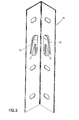
- Figure 3 shows a strut 15 according to the present invention.
- Said strut has right angled section obtained from a strip having an adequate thickness, by shearing and shaping the same, according to the usual art.
- a range of vertically spaced hooks 16 is provided, each hook projecting from the inner face of the respective wall.
- Each hook 16, as shown in figures 3, 4 is so vertically elongated as to be inserted through a vertical range of holes 8, 9, 10 and to project from the upper hole 10 with its end 16'.
- Each hook has a shape upwardly tapered so that it may follow, as accuratly as possible, the variation of the lenght of the holes 8 to 10 and may be forced in each one of the holes, through which is has been inserted, by interference of its edges with the ends of the elongated holes 8 to 10.
- the hook 16 has the edge nearer to the corner of the strut, perpendicular to the sheet panel and the opposed edge inclined with respect to said panel, so that, in the coupling of the panel and the strut, the interference between the inclined edges and the respective ends of the holes has more and more the tendency to wedge in the corner of the panel toward the strut.
- each hook 16 is provided with a front embos sment 17 which extends from below the base ' of the same hook and beyond the middle point of its height.
- This embossment is designed to generate a forcing of the hook also in the transversal direction of the holes 8, 9, 10 so that the coupling assures a complete forcing and eliminates every possible play.
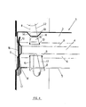
- the hook seen in frontal view in figure 4 shows the manner in which the hook 16 is forced through the holes 8, 9, 10 in the direction of their lenght, while the hook seen in sectional view shows the forcing in the transversal direction of the holes, said forcing being due to the embossment 17 and substantially interesting the holes 8 and 9.
Abstract
This invention relates to metallic shelvings and the like of the kind constituted by horizontal sheet panels (1) connected at their corners to struts (15), wherein each panel is provided with a peripheral vertical wall (2) extending along all the sides of the panel and reinforced on each side by alternated longitudinal ribs (3) and grooves (4) delimited each other by flat sides included on the plane of said peripheral wall, on said flat sides (6), near the corners of the panels, longitudinally elongated holes (8, 9, 10) are obtained disposed along vertical ranges, while each strut shows respective hooks (16) being able to be inserted and forced through all the holes of a respective range.
Description
- The present invention relates to some improvements to metallic shelvings particularly to the shelvings that are composed by horizontal sheet panels, or shelves, provided with a peripheral vertical wall connected at their corners to vertical struts usually obtained by angled metallic strips.
- A first aim of the invention is to provide metallic shelves or panels that may support a load greater than the load supported by the shelves of the prior art having the same thickness of the metallic sheets and the sime sizes in plane view.
- A second aim of the invention, is to strengthen the peripheral wall of the horizontal sheet panels, or shelves, and the junction between each shelf and the strut, so that a greater load may be applied along the strut, and so that a greater coupling stiffness, and consequently a greater stiffness of the whole structure, may be obtained.
- A further aim of the invention is to obtain a junction between each horizontal panel and the respective strut without any possibility of play, without any possibility of spontaneous release, said junction having the tendency to approach each corner of the horizontal panel to respect ive strut so that the stability and the load capacity of the structure are increased.
- To reach said aims, the improvements of the present invent ion are characterized in that each side of the vertical peripheral wall, of the horizontal sheet panel, is shaped such in a way that it shows an alternation of juxtaposed longitudinal ribs and grooves delimited one with respect to the other by flat sides inclined with respect to the plane of said peripheral wall, and is provided with a terminal edge folded inwardly of the same peripheral wall,said inclined flat sides and the respective folded terminal edge of a side at least of the peripheral wall, in proximity of each corner of the panel, being provided with respective longitudinally elongated holes located in a vertical range, so that a respective hook, projecting from the adjacent strut, may be inserted through all the holes of the vertical range.
- In a preferred embodiment of the invention, the longitudinal. ly elongated holes of each vertical range have a respective lenght decreasing from the lower hole to the upper hole, so that a correspondently tapered hook may be inserted through all the holes of the vertical range, forcing their lateral edges against the ends of said holes.
- In a further embodiment of the invention, the longitudinally elongated holes of each vertical range have the respective ends, nearer to the corner of the horizontal sheet panel, disposed along a common vertical line, while the other respective ends are disposed along an inclined line with respect to the vertical one and consequently the hook shows the inner lateral edge vertically directed while the outer lateral edge is inclined as said inclined line, so that in the coupling, the hook of each side of the strut has the tendency to push the respective corner of the horizontal panel toward the corner of the strut.
- In a further embodiment of the invention each hook of a strut is provided with an embossment starting from below the base of the hook and extending beyond the middle point of the height of the same hook, said embossment being able to cause a shrinkage in the transversal direction of each hole, and consequently forcing the hook into each hole both in the longitudinal and transversal direction.
- In a further embodiment of the invention, each horizontal sheet panel is provided on its horizontal plane surface with peripheral grooves, so that even said horizontal plane surface is strenghtened, thus avoiding the employment of tubular elements that up to now have been applied by welding on the underface of the sheet panels.
- An embodiment of the invention will now be described in more details with reference to the accompaying drawings, in which:
- Figure 1 is a sectional view of an horizontal sheet panel improved according to the invention;
- Figure 2 is a perspective esternal view of a corner of the sheet panel as represented in figure 1;
- Figure 3 is a perspective view of a strut designed to be coupled with the corner represented in figure 2;
- Figure 4 is a sectional view of the corner of figure 2 coupled with the strut of figure 3;
- As shown in figures 1 and 2, an
horizontal sheet panel 1 for composing metallic shelvings, according to the present invention, is provided with aperipheral wall 2, each side of which is so shaped as to show alternatedlongitudinal ribs 3 andgrooves 4, and alower edge 5 folded horizontal ly and inwardly for an appreciable vidht. -
Ribs 3 andgrooves 4 are delimited each other by inclinedflat sides 6. - As shown in the drawings, both
ribs 3 andgrooves 4 have respective top and bottom flat walls, but said top and bottom walls may have an arcuated shape. - In proximity of each
corner 7 of thepanel 1, and on at least one of the sides of the peripheral wall converging in said corner, the inclinedflat sides 6 and thebent edge 5 are provided withrespective holes - The
holes peripheral wall 2, so that they are flattened in the vertical direction. - The shape and the location of said holes allow the insertion of a flattened hook, inserted starting from the
hole 8, through all the holes of the vertical range, passing between the top and bottom walls of the ribs and the grooves respectively, as shown in figure 4. - Moreover, the holes of each vertical range, are gradually reduced in lenght starting from
hole 8toward hole 10. - In a preferred embodiment of the invention, and as better shown in figures 1 and 4, the ends of the
holes corners 7 are located along avertical line 11 or along a line perpendicular to thesheet panel 1, while the other ends are located along aline 12 inclined with respect to said panel, or to the vertical line. - The
horizontal sheet panel 1 is provided on its plane withperipheral grooves 13 limited by inclinedflat sides 14 said grooves providing a stiffness of the surface of the sheet panel, and avoiding the employment of additional stiffening elements, that, according to the known art have been employed and applied on the underface of the sheet by welding, with a consequent appreciable increasing of the production cost. - In the case of the sheet plane shown in figure 1, on the contrary, said stiffening grooves are obtained in the shaping phase of the sheet and consequently without an appre ciable increasing of the cost.
- As seen in figures 1, 2 and 4, the sheet panel of the invention, constitutes a component of a shelving showing high stiffness and mechanical resistance, because of the shaping of the peripheral wall and of the
grooves 13, so that, the thickness of the sheet and the plane size being equal, the sheet panel of the invention may support a load greater than the one supported by the sheet panels of the prior art. - Figure 3 shows a
strut 15 according to the present invention. - Said strut has right angled section obtained from a strip having an adequate thickness, by shearing and shaping the same, according to the usual art. According to the present invention on each wall of the angled strut, a range of vertically spaced
hooks 16 is provided, each hook projecting from the inner face of the respective wall. - Each
hook 16, as shown in figures 3, 4 is so vertically elongated as to be inserted through a vertical range ofholes upper hole 10 with its end 16'. - Each hook has a shape upwardly tapered so that it may follow, as accuratly as possible, the variation of the lenght of the
holes 8 to 10 and may be forced in each one of the holes, through which is has been inserted, by interference of its edges with the ends of theelongated holes 8 to 10. - As better shown in figure 4 according, to the preferred arrangement of the holes, the
hook 16 has the edge nearer to the corner of the strut, perpendicular to the sheet panel and the opposed edge inclined with respect to said panel, so that, in the coupling of the panel and the strut, the interference between the inclined edges and the respective ends of the holes has more and more the tendency to wedge in the corner of the panel toward the strut. - Furthermore, each
hook 16, is provided with a front embos sment 17 which extends from below the base' of the same hook and beyond the middle point of its height. This embossment is designed to generate a forcing of the hook also in the transversal direction of theholes - The coupling of the
hook 16 withholes - The hook seen in frontal view in figure 4 shows the manner in which the
hook 16 is forced through theholes embossment 17 and substantially interesting theholes - So, it can be seen from figure 4 that the coupling of the
sheet panel 1 with each strut is very rigid, with a consequent great increasing of the stiffness and the capacity load of the whole structure. - Moreover a greater capacity load of the coupling between the
hook 16 andholes embossment 17 strenghtens therespective hook 16, thus increasing the bending stress of the latter. - This description is made only by way of example and not as a limitation to the scope of the invention; many variations and modifications may be made and will become apperent to those skilled in the art; said modifications and variations fall within the true spirit and scope of the invention as pointed out by the appended claims.
Claims (5)
1. Improvements to metallic shelvings, of the kind composed by horizontal sheet panel and by vertical struts on which said horizontal sheet panels are mounted at each corner, said horizontal sheet panels being provided at each side with a vertical peripheral wall, characterized in that each side of the vertical peripheral wall (2) of the horizon tal sheet panel (1)is shaped such in a way as to show an al ternation of juxtaposed longitudinal ribs (3) and grooves (4) delimited one with respect to the other by flat sides (6) inclined with respect to the plane of said peripheral wall, said inclined flat sides and the respective folded terminal edge of at least a side of the peripheral wall, in proximity of each corner of the panel,being provided with respective longitudinally elongated holes (8, 9, 10) located in a vertical range, so that a respective hook (16) projecting from the adjacent strut (15) may be inserted through all the holes of the vertical range.
2. Improvements to metallic shelvings as claimed in claim 1. characterized in that, in a preferred embodiment of the invention,the longitudinally elongated holes of each vertical range have a respective lenght decreasing from the lower hole (8) to the upper hole (10), so that a correspon dently tapered hook (16) may be inserted through all the holes of the vertical range, forcing their lateral edges against the ends of said holes.
3. Improvements to metallic shelvings as claimed in claims 1,2 characterized in that the longitudinally elongated holes of each vertical range have the respective ends, closer to the corner of the horizontal sheet panel, disposed along a common vertical line (11), while the other respective ends are disposed along an inclined line (12) with respect to the vertical one and consequently the hook (16) shows the inner lateral edge vertically directed while the outer lateral edge is inclined as said inclined line, so that in the coupling, the hook of each side of the strut, has the tendency to push the respective corner of the horizontal panel toward the corner of the strut.
4. Improvements to metallic shelvings according to claims 1, 2 characterized in that each hook (16) of a strut (15) is provided with an embossment (17) starting from below the base of the hook and extending beyond the middle point of the height of the same hook, said embossment being able to cause a shrinkage in the transversal direction of each hole.
5. Improvements to metallic shelvings according to claim 1 characterized in that each horizontal sheet panel 1 is provided on its horizontal plane surface with peripheral grooves (13).
Applications Claiming Priority (2)
| Application Number | Priority Date | Filing Date | Title |
|---|---|---|---|
| IT27246/79A IT1124967B (en) | 1979-11-13 | 1979-11-13 | REFINEMENTS FOR METAL SHELVING |
| IT2724679 | 1979-11-13 |
Publications (1)
| Publication Number | Publication Date |
|---|---|
| EP0029012A1 true EP0029012A1 (en) | 1981-05-20 |
Family
ID=11221270
Family Applications (1)
| Application Number | Title | Priority Date | Filing Date |
|---|---|---|---|
| EP80830078A Ceased EP0029012A1 (en) | 1979-11-13 | 1980-10-08 | Metallic shelving |
Country Status (6)
| Country | Link |
|---|---|
| EP (1) | EP0029012A1 (en) |
| JP (1) | JPS56158610A (en) |
| CA (1) | CA1151600A (en) |
| DK (1) | DK480580A (en) |
| ES (1) | ES260962Y (en) |
| IT (1) | IT1124967B (en) |
Cited By (1)
| Publication number | Priority date | Publication date | Assignee | Title |
|---|---|---|---|---|
| GB2324709A (en) * | 1997-05-02 | 1998-11-04 | Dexion Group Plc | Beam connector for racking systems |
Citations (3)
| Publication number | Priority date | Publication date | Assignee | Title |
|---|---|---|---|---|
| GB952576A (en) * | 1962-10-09 | 1964-03-18 | Palmer Shile Co | Improvements in or relating to beams for adjustable storage racks |
| DE1186182B (en) * | 1958-11-24 | 1965-01-28 | Heinz Nuelken | Shelf, consisting of corner posts and height-adjustable shelves |
| FR2344249A1 (en) * | 1976-03-15 | 1977-10-14 | Guillemin Henri | Sectional shelving with angle iron posts - has rectangular shelves with returned L:flanges engaged by post flange flaps |
-
1979
- 1979-11-13 IT IT27246/79A patent/IT1124967B/en active
-
1980
- 1980-10-08 EP EP80830078A patent/EP0029012A1/en not_active Ceased
- 1980-10-10 ES ES1980260962U patent/ES260962Y/en not_active Expired
- 1980-10-23 CA CA000363105A patent/CA1151600A/en not_active Expired
- 1980-10-29 JP JP15197880A patent/JPS56158610A/en active Pending
- 1980-11-11 DK DK480580A patent/DK480580A/en not_active Application Discontinuation
Patent Citations (3)
| Publication number | Priority date | Publication date | Assignee | Title |
|---|---|---|---|---|
| DE1186182B (en) * | 1958-11-24 | 1965-01-28 | Heinz Nuelken | Shelf, consisting of corner posts and height-adjustable shelves |
| GB952576A (en) * | 1962-10-09 | 1964-03-18 | Palmer Shile Co | Improvements in or relating to beams for adjustable storage racks |
| FR2344249A1 (en) * | 1976-03-15 | 1977-10-14 | Guillemin Henri | Sectional shelving with angle iron posts - has rectangular shelves with returned L:flanges engaged by post flange flaps |
Cited By (2)
| Publication number | Priority date | Publication date | Assignee | Title |
|---|---|---|---|---|
| GB2324709A (en) * | 1997-05-02 | 1998-11-04 | Dexion Group Plc | Beam connector for racking systems |
| GB2324709B (en) * | 1997-05-02 | 2001-12-05 | Dexion Group Plc | Beam end connector |
Also Published As
| Publication number | Publication date |
|---|---|
| ES260962U (en) | 1982-04-16 |
| JPS56158610A (en) | 1981-12-07 |
| IT7927246A0 (en) | 1979-11-13 |
| ES260962Y (en) | 1982-11-16 |
| CA1151600A (en) | 1983-08-09 |
| IT1124967B (en) | 1986-05-14 |
| DK480580A (en) | 1981-05-14 |
Similar Documents
| Publication | Publication Date | Title |
|---|---|---|
| US3252614A (en) | Stackable pan | |
| US3693556A (en) | Sectional shelving | |
| US4821649A (en) | Sheet metal shelving | |
| US5299509A (en) | Connectors for shelves and bins | |
| US3278043A (en) | Storage rack | |
| US3788242A (en) | Shelving units | |
| US5145244A (en) | Easily disassembled furniture | |
| US4295693A (en) | Knocked-down cabinet | |
| JPS6211842B2 (en) | ||
| US3237779A (en) | Supporting frame | |
| US2225958A (en) | Casing | |
| US3269338A (en) | Boltless clip | |
| US3216377A (en) | Bookstacks | |
| US4066370A (en) | Assembling piece | |
| GB2044080A (en) | Modular frame for shelving | |
| EP0029012A1 (en) | Metallic shelving | |
| EP2430947B1 (en) | Presentation shelf with low tray distance | |
| JPH0819439A (en) | Method for connecting document filing cabinet and the like | |
| US3268089A (en) | Deck section for storage rack | |
| EP0044282A2 (en) | Metallic shelving provided with multiple interlocking means, and components designed for producing this shelving | |
| EP0752223A2 (en) | Coupling device for light-duty metal set of shelves | |
| US4944412A (en) | Element for slanted desk top rack | |
| US3487790A (en) | Knockdown shelving | |
| US4110052A (en) | Multiple element for forming various structures when connected to box-form panels for furniture or the like | |
| EP0808589A2 (en) | Device for interlocking complementary pairs of components of sets of shelves made of metal plate |
Legal Events
| Date | Code | Title | Description |
|---|---|---|---|
| PUAI | Public reference made under article 153(3) epc to a published international application that has entered the european phase |
Free format text: ORIGINAL CODE: 0009012 |
|
| AK | Designated contracting states |
Designated state(s): AT BE CH DE FR GB LU NL SE |
|
| 17P | Request for examination filed |
Effective date: 19811028 |
|
| RAP1 | Party data changed (applicant data changed or rights of an application transferred) |
Owner name: METALGAMMA S.N.C. DI L.G. BELLONI & C. |
|
| STAA | Information on the status of an ep patent application or granted ep patent |
Free format text: STATUS: THE APPLICATION HAS BEEN REFUSED |
|
| 18R | Application refused |
Effective date: 19840225 |
|
| RIN1 | Information on inventor provided before grant (corrected) |
Inventor name: BELLONI, LUCIANO GIULIO |