EP0028896B1 - Apparatus for use by a marine vessel in handling anchors - Google Patents
Apparatus for use by a marine vessel in handling anchors Download PDFInfo
- Publication number
- EP0028896B1 EP0028896B1 EP80303785A EP80303785A EP0028896B1 EP 0028896 B1 EP0028896 B1 EP 0028896B1 EP 80303785 A EP80303785 A EP 80303785A EP 80303785 A EP80303785 A EP 80303785A EP 0028896 B1 EP0028896 B1 EP 0028896B1
- Authority
- EP
- European Patent Office
- Prior art keywords
- pin
- deck
- drum
- vessel
- pins
- Prior art date
- Legal status (The legal status is an assumption and is not a legal conclusion. Google has not performed a legal analysis and makes no representation as to the accuracy of the status listed.)
- Expired
Links
- 230000000712 assembly Effects 0.000 claims description 9
- 238000000429 assembly Methods 0.000 claims description 9
- 230000001105 regulatory effect Effects 0.000 claims 1
- 238000000034 method Methods 0.000 description 8
- 238000005553 drilling Methods 0.000 description 3
- 230000007246 mechanism Effects 0.000 description 3
- 230000004913 activation Effects 0.000 description 2
- 239000003550 marker Substances 0.000 description 2
- 238000004873 anchoring Methods 0.000 description 1
- 230000003111 delayed effect Effects 0.000 description 1
- 239000011796 hollow space material Substances 0.000 description 1
- JEIPFZHSYJVQDO-UHFFFAOYSA-N iron(III) oxide Inorganic materials O=[Fe]O[Fe]=O JEIPFZHSYJVQDO-UHFFFAOYSA-N 0.000 description 1
- 230000008439 repair process Effects 0.000 description 1
- 239000011800 void material Substances 0.000 description 1
- XLYOFNOQVPJJNP-UHFFFAOYSA-N water Substances O XLYOFNOQVPJJNP-UHFFFAOYSA-N 0.000 description 1
- 238000003466 welding Methods 0.000 description 1
Images

Classifications
-
- B—PERFORMING OPERATIONS; TRANSPORTING
- B63—SHIPS OR OTHER WATERBORNE VESSELS; RELATED EQUIPMENT
- B63B—SHIPS OR OTHER WATERBORNE VESSELS; EQUIPMENT FOR SHIPPING
- B63B21/00—Tying-up; Shifting, towing, or pushing equipment; Anchoring
- B63B21/22—Handling or lashing of anchors
-
- B—PERFORMING OPERATIONS; TRANSPORTING
- B63—SHIPS OR OTHER WATERBORNE VESSELS; RELATED EQUIPMENT
- B63B—SHIPS OR OTHER WATERBORNE VESSELS; EQUIPMENT FOR SHIPPING
- B63B21/00—Tying-up; Shifting, towing, or pushing equipment; Anchoring
- B63B21/04—Fastening or guiding equipment for chains, ropes, hawsers, or the like
- B63B21/10—Fairleads
Definitions
- This invention relates to apparatus for use by a marine vessel in handling anchors and the like, including bringing anchors on board the vessel.
- Marine vessels perform a variety of tasks, one of which is the handling of anchors. This is particularly important in the offshore oil and gas industry where very large drilling rigs are kept in position by a plurality of anchors. Because of their size and the nature of the anchoring procedures, these drilling rigs require assistance from other vessels in anchor handling procedures.
- anchor handling describes a wide variety of operations including the following: receiving the anchor from the rig, carrying the anchor to its proper location and deploying it, extracting the anchor from the sea bottom and hauling it to the surface, bringing the anchor on board the retrieving vessel, and carrying the anchor back to the rig.
- This extra deck space makes the supply-tug more suitable than the tug for those anchor handling operations involving the boarding of anchors.
- the anchor When an anchor is brought on board, even in moderately calm seas, the anchor is jostled about the deck.
- the supply-tug deck provides ample room for the anchor to move about without becoming entangled with the men and equipment located at the forward deck of the vessel. Additionally, the extra deck space on the supply-tug provides necessary storage for the anchor as well.as other items associated with anchors such as anchor buoys and cables.
- the usual method of extracting a drilling rig anchor from the sea floor involves the use of a cable called a pennant line. One end of the pennant line is attached to the anchor. The other end is attached to the anchor's marker buoy.
- the pennant line When the anchor is in place in the sea floor, the pennant line is slack, the buoy being allowed to float relatively free.
- the retrieving vessel locates the buoy and brings it on board.
- the pennant line which was attached to the buoy is then attached to a winch located approximately in the center of the vessel and the slack is taken out of the line.
- breaking anchor The next step involved in extracting the anchor is known as "breaking anchor".
- the traditional way of centering the pennant line has been to use a pair of vertical pins located at the center of the vessel's stern in combination with a winch situated at the vesel's center, forward of the stern.
- Vertical pins are employed on both tugs and supply-tugs while breaking and hauling in the anchor. Because the supply-tug is used for jobs not normally performed by the tug, particularly the boarding of anchors, there has been a divergence in the development of vertical pins used on tugs as compared with those vertical pins used on supply-tugs. Due to the weight of the anchor and in order to avoid interference with the anchor, the vertical pins used on a supply-tug must be capable of "disappearing" i.e. there must be no manifestation of their presence on deck immediately prior to bringing the anchor on board.
- Vertical pins generally used today on a supply-tug are best described as dowels which fit into cylindrical cavities located at the stern beneath the deck. Many such vertical pins are manually inserted and manually removed from the cavity.
- Some supply-tugs are equipped with hydraulically operated pins which are normally stored inside their cylindrical cavity, the top of the pin being flush with the deck. The pins are hydraulically raised and lowered as needed.
- Dutch Patent Application No. NL-A-7 801 672 discloses a hawser guide for use by a marine vessel and comprising a pair of pulley or pin assemblies each comprising a pulley or pin, a frame providing rotatable supports for the pin at both ends of the pin, a rotatable shaft or drum to which the frame is attached, a means for rotating the drum to rotate the pin or pulley between a position in which it projects above a deck of the vessel and a position in which it does not project above the deck, a means for preventing drum rotation, and a housing arrangement recessed into the deck of the vessel for accommodating the pin assemblies when the pins do not project above the deck.
- each pulley can be rotated below deck level into the housing arrangement and the upper side thereof can be closed off by a cover or lid.
- the cover has to be positioned by way of a separate operation, presumably a manual operation, after the pins have been rotated into the housing arrangement.
- apparatus for use by a marine vessel in handling anchors and the like including bringing anchors on board the vessel, the apparatus comprising a pair of pin assemblies each comprising a pin, a frame providing rotatable support for the pin at both ends of the pin, a rotatable drum to which the frame is attached, a means for rotating the drum to rotate the pin between a position in which it projects above a deck of the vessel and a position in which it does not project above the deck, a means for preventing drum rotation, a housing arrangement recessed into the deck of the vessel to accommodate the pins when the pins do not project above the deck, and a cover for closing the housing arrangement when the pins do not project above the deck, characterised in that;
- the cover plate attached to the frame and drum of each pin assembly automatically forms part of the deck when the pin is moved to the horizontal position, thereby automatically covering the pins and eliminating the pins as a source of obstructions and entanglement, in particular when boarding an anchor.
- Figure 1 illustrates a pair of pin assemblies, 1 Up being the port side pin assembly and 10s being the starboard side pin assembly. Arrow 11 indicates the direction of the stern of the vessel. Pin assemblies 10p and 10s are mirror images of each other, the component parts of each being identical.
- Frame 14 is connected to drum 16, the connection preferably being made by welding.
- Drum 16 rotates about its journal 18.
- Journal box 19 transmits the load of the drum and attached components to housing 13.
- Figure 1 shows that pin assemblies 10p and 10s are spaced apart, the distance 15 between the inside surfaces of the pins being approximately 508 mm (20 inches) in this preferred embodiment of the invention.
- the distance 15 must be large enough to accommodate the passage therethrough of the pennant line as well as large cable connectors and the like.
- Drum rotation and hence movement of the pin from a horizontal to a vertical position is preferably provided by piston and cylinder arrangement 24, shown in Figures 2 and 3.
- Arrangement 24 is pivotally connected to the base mounting 31.
- the piston rod 25 of arrangement 24 is pivotally connected to drum 16, the connection in the preferred embodiment being made via drum extension 27.
- Arrangement 24 is preferably operated pneumatically, thereby making use of the readily available pneumatic system which exists on most vessels. As the piston rod 25 extends causing drum 16 to rotate, the attached pin 12 is moved from a horizontal to a vertical position.
- Manhole cover 20 facilitates access to arrangement 24 for repairs.
- load bearing member is used to maintain the vertical position of the pin.
- load bearing member is in the form of slideable wedge 33 shown in Figure 5. (For the sake of clarity, wedge 33 is not shown in Figures 3 and 4.)
- the vertical position of pin 12 is just slightly less than truly vertical. Such design urges the pin to fall to its horizontal position, thereby removing the possibility that the pin will remain balanced in the vertical position after wedge 33 is removed.
- a device (not shown) already known in the art is used to coordinate the timing of the activation of arrangement 24 relative to arrangement 30. Said device is also used to coordinate the activation of one pin assembly relative to the other pin assembly.
- cover plate 22 is attached to frame 14 and drum 16.
- the plate 22, pin 12, and frame 14 move as one unit as drum 16 is rotated.
- cover plate 22 is flush with the deck 21.
- the housing 13 is recessed below the deck 21 so that the housing top 41 is flush with the deck 21. Therefore, when the pin is in its horizontal position, the entire pin assembly is below deck except the cover plate 22 and housing top 41 which form a part of the deck.
- FIGs 2 and 3 depict the preferred configuration of housing 13.
- the housing 13 has an upper portion 51 which has the shape of a rectangular box whose base is several times that of its height.
- Upper portion 51 houses the pin 12, frame 14, drum 16, asrrangement 30 and wedge 33 (arrangement 30 and wedge 33 are shown in Figure 5).
- Housing 13 also has a lower portion 53 which has the shape of a rectangular box whose height is several times that of its base.
- the lower portion 53 serves mainly to house arrangement 24 and support upper portion 51.
- the preferred configuration makes the housing readily adaptable to most vessels.
- the lower portion 53 fits into the stern of the vessel, which in most vessels is an area that is usually hollow space, void of rudder mechanisms.
- the upper portion 51 is located directly above rudder mechanisms and the like on most vessels, but because upper portion 51 is relatively shallow, it does not interfere with these mechanisms.
- the base plate 65 of upper portion 51 and the base plate 63 of lower portion 53 are attached to and supported by structural members (not shown) of the vessel.
Landscapes
- Chemical & Material Sciences (AREA)
- Engineering & Computer Science (AREA)
- Combustion & Propulsion (AREA)
- Mechanical Engineering (AREA)
- Ocean & Marine Engineering (AREA)
- Filling Or Discharging Of Gas Storage Vessels (AREA)
- Bridges Or Land Bridges (AREA)
- Laying Of Electric Cables Or Lines Outside (AREA)
- Warehouses Or Storage Devices (AREA)
- Massaging Devices (AREA)
- Rolls And Other Rotary Bodies (AREA)
Description
- This invention relates to apparatus for use by a marine vessel in handling anchors and the like, including bringing anchors on board the vessel.
- Marine vessels perform a variety of tasks, one of which is the handling of anchors. This is particularly important in the offshore oil and gas industry where very large drilling rigs are kept in position by a plurality of anchors. Because of their size and the nature of the anchoring procedures, these drilling rigs require assistance from other vessels in anchor handling procedures.
- The term "anchor handling" describes a wide variety of operations including the following: receiving the anchor from the rig, carrying the anchor to its proper location and deploying it, extracting the anchor from the sea bottom and hauling it to the surface, bringing the anchor on board the retrieving vessel, and carrying the anchor back to the rig. Some anchor handling procedures involve all of the above, while other procedures involve only some of the above.
- There are basically two types of marine vessels which assist the rig in anchor handling, the tug and supply-tug. The latter resembles the traditional tug except that it has an extended rear deck section.
- This extra deck space makes the supply-tug more suitable than the tug for those anchor handling operations involving the boarding of anchors. When an anchor is brought on board, even in moderately calm seas, the anchor is jostled about the deck. The supply-tug deck provides ample room for the anchor to move about without becoming entangled with the men and equipment located at the forward deck of the vessel. Additionally, the extra deck space on the supply-tug provides necessary storage for the anchor as well.as other items associated with anchors such as anchor buoys and cables.
- The usual method of extracting a drilling rig anchor from the sea floor involves the use of a cable called a pennant line. One end of the pennant line is attached to the anchor. The other end is attached to the anchor's marker buoy.
- When the anchor is in place in the sea floor, the pennant line is slack, the buoy being allowed to float relatively free. When the anchor is to be extracted from the sea floor, the retrieving vessel locates the buoy and brings it on board. The pennant line which was attached to the buoy is then attached to a winch located approximately in the center of the vessel and the slack is taken out of the line. The next step involved in extracting the anchor is known as "breaking anchor".
- In this step, a tremendous pulling force is gradually applied to the anchor via the pennant line until the anchor is freed from the seabed. Because of the tremendous tension in the pennant line while breaking anchor, it is important to keep the pennant line centered at the vessel's stern. Centered thusly, the vessel's engines are used more efficiently and there is less danger of the vessel capsizing. After breaking anchor and while hauling the anchor to the surface, it is desirable to maintain the pennant line centered at the vessel's stern instead of allowing the line to rub back and forth across the stern.
- The traditional way of centering the pennant line has been to use a pair of vertical pins located at the center of the vessel's stern in combination with a winch situated at the vesel's center, forward of the stern.
- Vertical pins are employed on both tugs and supply-tugs while breaking and hauling in the anchor. Because the supply-tug is used for jobs not normally performed by the tug, particularly the boarding of anchors, there has been a divergence in the development of vertical pins used on tugs as compared with those vertical pins used on supply-tugs. Due to the weight of the anchor and in order to avoid interference with the anchor, the vertical pins used on a supply-tug must be capable of "disappearing" i.e. there must be no manifestation of their presence on deck immediately prior to bringing the anchor on board.
- Vertical pins generally used today on a supply-tug are best described as dowels which fit into cylindrical cavities located at the stern beneath the deck. Many such vertical pins are manually inserted and manually removed from the cavity. Some supply-tugs are equipped with hydraulically operated pins which are normally stored inside their cylindrical cavity, the top of the pin being flush with the deck. The pins are hydraulically raised and lowered as needed.
- There have been problems associated with the dowel-cylindrical cavity type of vertical pin used on supply-tugs. Often, when such pins are in their raised position, the pennant line is pulled very strongly against one of the pins. When subjected to such a horizontal load the pin, being supported at only one end, often becomes bent. Such binding causes the dowel to become stuck in its cavity. So stock, the pin is a very aggravating and dangerous nuisance because the anchor must either be pulled over the obstructing pin or the anchor boarding procedure must be delayed until the deformed pin is cut off. Also, because this type of vertical pin requires a very close fit between the dowel and the cavity, rust and debris have been known to cause the dowel to stick in its cavity.
- These problems have generally not been encountered with the vertical pins used on tugs. Because a tug normally doesn't board anchors, there is no need to have pins which are capable of "disappearing" from the deck. This means the vertical pin can be sufficiently strengthened against deformation by various frames and supporting devices securely fixed to the deck.
- Dutch Patent Application No. NL-A-7 801 672 discloses a hawser guide for use by a marine vessel and comprising a pair of pulley or pin assemblies each comprising a pulley or pin, a frame providing rotatable supports for the pin at both ends of the pin, a rotatable shaft or drum to which the frame is attached, a means for rotating the drum to rotate the pin or pulley between a position in which it projects above a deck of the vessel and a position in which it does not project above the deck, a means for preventing drum rotation, and a housing arrangement recessed into the deck of the vessel for accommodating the pin assemblies when the pins do not project above the deck. When the hawser guide is not required, each pulley can be rotated below deck level into the housing arrangement and the upper side thereof can be closed off by a cover or lid. Evidently, the cover has to be positioned by way of a separate operation, presumably a manual operation, after the pins have been rotated into the housing arrangement.
- According to the present invention there is provided apparatus for use by a marine vessel in handling anchors and the like, including bringing anchors on board the vessel, the apparatus comprising a pair of pin assemblies each comprising a pin, a frame providing rotatable support for the pin at both ends of the pin, a rotatable drum to which the frame is attached, a means for rotating the drum to rotate the pin between a position in which it projects above a deck of the vessel and a position in which it does not project above the deck, a means for preventing drum rotation, a housing arrangement recessed into the deck of the vessel to accommodate the pins when the pins do not project above the deck, and a cover for closing the housing arrangement when the pins do not project above the deck, characterised in that;
- the cover is constituted by a cover plate for each pin assembly, the plate being attached to the frame and drum of the associated pin assembly, and the plate forming a part of the deck of the vessel and substantially wholly covering the associated pin when the rotational axis of the pin is horizontally disposed and extending alongside of and beyond the lower end of the pin when the pin projects above the deck; and
- the housing arrangement is constituted by a housing for each pin assembly, the housing being recessed into the floor of the deck of the vessel in such a way that the top of the housing forms part of the deck of the vessel.
- In apparatus according to the invention, the cover plate attached to the frame and drum of each pin assembly automatically forms part of the deck when the pin is moved to the horizontal position, thereby automatically covering the pins and eliminating the pins as a source of obstructions and entanglement, in particular when boarding an anchor.
- The invention will now be further described, by way of illustrative and non-limiting example, with reference to the accompanying drawings, in which:
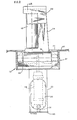
- Figure 1 is a plan view, partly broken away, of port side and starboard side pin assemblies of an apparatus embodying the invention, pins of the assemblies being in a horizontal position;
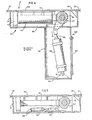
- Figure 2 is elevational view, partly broken away, of the port side pin assembly looking aft;
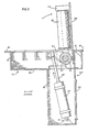
- Figure 3 is a sectional view taken along line 3-3 in Figure 2;
- Figure 4 is a view taken along the same line as Figure 3, Figure 4 showing the pin in the horizontal position; and
- Figure 5 is an elevational view, partly in section, of an upper portion of a housing of the pin assembly.
- Figure 1 illustrates a pair of pin assemblies, 1 Up being the port side pin assembly and 10s being the starboard side pin assembly.
Arrow 11 indicates the direction of the stern of the vessel. Pin assemblies 10p and 10s are mirror images of each other, the component parts of each being identical. - Using assembly 10p in Figure 1 to illustrate the component parts of a typical pin assembly, said assembly is encased in
housing 13.Pin 12 is rotatably mounted inframe 14. In Figure 1, the pin is shown in its horizontal position. In Figure 2, the pin is shown in its vertical position.Frame 14 provides support forpin 12 at both ends of the pin. -
Frame 14 is connected todrum 16, the connection preferably being made by welding.Drum 16 rotates about itsjournal 18. Journal box 19 transmits the load of the drum and attached components tohousing 13. - Assembly 10s in Figure 1 shows cover
plate 22 in position. - Figure 1 shows that pin assemblies 10p and 10s are spaced apart, the
distance 15 between the inside surfaces of the pins being approximately 508 mm (20 inches) in this preferred embodiment of the invention. Thedistance 15 must be large enough to accommodate the passage therethrough of the pennant line as well as large cable connectors and the like. - Drum rotation and hence movement of the pin from a horizontal to a vertical position is preferably provided by piston and
cylinder arrangement 24, shown in Figures 2 and 3.Arrangement 24 is pivotally connected to the base mounting 31. Thepiston rod 25 ofarrangement 24 is pivotally connected to drum 16, the connection in the preferred embodiment being made viadrum extension 27.Arrangement 24 is preferably operated pneumatically, thereby making use of the readily available pneumatic system which exists on most vessels. As thepiston rod 25 extends causingdrum 16 to rotate, the attachedpin 12 is moved from a horizontal to a vertical position.Manhole cover 20 facilitates access toarrangement 24 for repairs. - Use of piston and
cylinder arrangement 24 to maintain this vertical position, especially when a pennant line or the like is pushing against the pin, would unduly strain the pressure system operating the arrangement. Therefore, a load bearing member is used to maintain the vertical position of the pin. In the preferred embodiment, such load bearing member is in the form ofslideable wedge 33 shown in Figure 5. (For the sake of clarity,wedge 33 is not shown in Figures 3 and 4.) - When
drum 16 is rotated so as to liftpin 12 to its vertical position, theflat surface 37 ofdrum 16 is moved to a position adjacent and parallel toflat surface 35 ofwedge 33.Wedge 33 is then moved to its extended position,surface 35 engagingsurface 37.Arrangement 24 may now be relaxed,wedge 33 preventing drum rotation, thereby maintaining the pin in the vertical position. To lower the pin to a horizontal position, the procedure is reversed.Arrangement 24 is activated, taking the pressure offwedge 33.Wedge 33 is then withdrawn to its retracted position which allows the drum to rotate, thereby moving the pin to its horizontal position. Piston andcylinder arrangement 30 is the driving force behindwedge 33. It is preferably operated pneumatically, drawing from the same source asarrangement 24. - In the preferred embodiment, the vertical position of
pin 12 is just slightly less than truly vertical. Such design urges the pin to fall to its horizontal position, thereby removing the possibility that the pin will remain balanced in the vertical position afterwedge 33 is removed. - A device (not shown) already known in the art is used to coordinate the timing of the activation of
arrangement 24 relative toarrangement 30. Said device is also used to coordinate the activation of one pin assembly relative to the other pin assembly. - As shown in Figures 3, 4 and 5,
cover plate 22 is attached to frame 14 anddrum 16. Theplate 22,pin 12, andframe 14 move as one unit asdrum 16 is rotated. Whenpin 12 is in the horizontal position,cover plate 22 is flush with thedeck 21. - As shown in Figures 2, 3 and 4; the
housing 13 is recessed below thedeck 21 so that thehousing top 41 is flush with thedeck 21. Therefore, when the pin is in its horizontal position, the entire pin assembly is below deck except thecover plate 22 andhousing top 41 which form a part of the deck. - Figures 2 and 3 depict the preferred configuration of
housing 13. Thehousing 13 has anupper portion 51 which has the shape of a rectangular box whose base is several times that of its height.Upper portion 51 houses thepin 12,frame 14,drum 16,asrrangement 30 and wedge 33 (arrangement 30 andwedge 33 are shown in Figure 5). -
Housing 13 also has alower portion 53 which has the shape of a rectangular box whose height is several times that of its base. Thelower portion 53 serves mainly tohouse arrangement 24 and supportupper portion 51. - The preferred configuration makes the housing readily adaptable to most vessels. The
lower portion 53 fits into the stern of the vessel, which in most vessels is an area that is usually hollow space, void of rudder mechanisms. Theupper portion 51 is located directly above rudder mechanisms and the like on most vessels, but becauseupper portion 51 is relatively shallow, it does not interfere with these mechanisms. Thebase plate 65 ofupper portion 51 and thebase plate 63 oflower portion 53 are attached to and supported by structural members (not shown) of the vessel. - When hauling in and boarding a submerged anchor, the preferred method of using the disclosed apparatus is as follows:
- With the
pins 12 in their horizontal position, the vessel's winch cable is pulled from the winch (located in the vessel's center), across the aft deck, beyond the stern and (usually with the aid of a diver or a dinghy), is attached to the anchor's marker buoy. The winch cable, extending past the stern into the water, is allowed to move to either the port or starboard side. Then, the pin on the side of the vessel opposite the winch cable is-raised. For example, if the winch cable is on the port side, the starboard pin will be raised. - Then the cable will be allowed to move, or the vessel will move, so that the winch cable is bearing against the raised pin. The remaining pin is now extended to its vertical position, thereby "trapping" the cable between the two pins.
- The winch is then activated, pulling the winch cable and the attached buoy toward the vessel's stern. When the buoy nears the vessel's stern, both pins are put in their horizontal position. In this position the buoy may be brought on board with ease and without entangling the buoy, cable line, and pins.
- While holding the pennant line, the buoy is detached from the pennant line and moved to one side of the deck for storage. The winch cable is then attached to the pennant line and the pennant line is trapped between the two pins in the same 'manner as was the winch cable. The pins are maintained in their vertical position while "breaking" and hauling in the anchor.
- When the anchor has been brought to the surface and is at the stern ready to be boarded the pins are lowered to their horizontal position. The anchor may then be brought on board, the deck being free of obstructing, entangling pins and the pins being tucked away, safe from the tremendous weight and force of the anchor that is being moved about the deck.
Claims (5)
Applications Claiming Priority (2)
| Application Number | Priority Date | Filing Date | Title |
|---|---|---|---|
| US06/092,014 US4278041A (en) | 1979-11-07 | 1979-11-07 | Anchor handling guides |
| US92014 | 1993-07-15 |
Publications (2)
| Publication Number | Publication Date |
|---|---|
| EP0028896A1 EP0028896A1 (en) | 1981-05-20 |
| EP0028896B1 true EP0028896B1 (en) | 1985-01-16 |
Family
ID=22230828
Family Applications (1)
| Application Number | Title | Priority Date | Filing Date |
|---|---|---|---|
| EP80303785A Expired EP0028896B1 (en) | 1979-11-07 | 1980-10-24 | Apparatus for use by a marine vessel in handling anchors |
Country Status (6)
| Country | Link |
|---|---|
| US (1) | US4278041A (en) |
| EP (1) | EP0028896B1 (en) |
| DK (1) | DK461380A (en) |
| ES (1) | ES267077Y (en) |
| IE (1) | IE50336B1 (en) |
| NO (1) | NO153682C (en) |
Families Citing this family (9)
| Publication number | Priority date | Publication date | Assignee | Title |
|---|---|---|---|---|
| US4347800A (en) * | 1980-01-21 | 1982-09-07 | Fritz Culver, Inc. | Retractable towing pin |
| NO146271C (en) | 1980-06-12 | 1982-09-01 | Ulstein Trading | DEVICE FOR CHAIN LOCKING, WIRE, LINE OR LIKE A STATION CONSTRUCTION, SPECIAL BOAT TIRE |
| NO153527C (en) * | 1983-08-17 | 1986-04-09 | Per H Hystad | READ FOR TOWNS ON A SUPPLY VESSEL OR LIKE. |
| WO2003086854A2 (en) * | 2002-04-11 | 2003-10-23 | Wilcox Jeffrey S | Marine pneumatic system |
| NO20040355A (en) * | 2004-01-26 | 2005-05-30 | Rolls Royce Marine As | Device by a tow pin for guiding a cable on a vessel |
| NO20044486A (en) * | 2004-10-20 | 2006-01-02 | Karmoey Winch As | Device by stopper mechanism |
| NO332933B1 (en) * | 2005-08-18 | 2013-02-04 | Rolls Royce Marine As | System for handling a wire, chain and cable on board a vessel |
| KR101466972B1 (en) | 2013-05-24 | 2014-11-28 | 김무광 | Cable guide device for towing device |
| CN103434615A (en) * | 2013-08-15 | 2013-12-11 | 蔡端朝 | Anchor windlass |
Family Cites Families (4)
| Publication number | Priority date | Publication date | Assignee | Title |
|---|---|---|---|---|
| US1299529A (en) * | 1919-01-31 | 1919-04-08 | Harry W Young | Deck-cleat. |
| US2783025A (en) * | 1954-11-08 | 1957-02-26 | Western Electric Co | Cable guiding apparatus |
| US3588051A (en) * | 1969-05-28 | 1971-06-28 | Howard M Leeming | Towing cable control apparatus |
| NL7801672A (en) * | 1978-02-14 | 1979-08-16 | Mampaey Marine Engineering B V | Tugboat hawser guide - has rollers extending above vessel deck level, and located in holders lockable in active position, and foldable below deck when not required |
-
1979
- 1979-11-07 US US06/092,014 patent/US4278041A/en not_active Expired - Lifetime
-
1980
- 1980-10-24 EP EP80303785A patent/EP0028896B1/en not_active Expired
- 1980-10-30 DK DK461380A patent/DK461380A/en not_active Application Discontinuation
- 1980-11-04 ES ES1980267077U patent/ES267077Y/en not_active Expired
- 1980-11-06 IE IE2297/80A patent/IE50336B1/en unknown
- 1980-11-06 NO NO803334A patent/NO153682C/en unknown
Also Published As
| Publication number | Publication date |
|---|---|
| NO153682C (en) | 1986-05-07 |
| DK461380A (en) | 1981-05-08 |
| IE802297L (en) | 1981-05-07 |
| IE50336B1 (en) | 1986-04-02 |
| NO803334L (en) | 1981-05-08 |
| NO153682B (en) | 1986-01-27 |
| EP0028896A1 (en) | 1981-05-20 |
| US4278041A (en) | 1981-07-14 |
| ES267077Y (en) | 1983-08-16 |
| ES267077U (en) | 1983-02-16 |
Similar Documents
| Publication | Publication Date | Title |
|---|---|---|
| US5069580A (en) | Subsea payload installation system | |
| US5190107A (en) | Heave compensated support system for positioning subsea work packages | |
| US4020779A (en) | Chain/wire rope connector assembly for anchor | |
| US4312287A (en) | Apparatus for handling submersibles at sea | |
| JPS61501017A (en) | remote controlled submersible | |
| JPS584684A (en) | Anchoring facility | |
| GB2150903A (en) | Method and assembly for launching or retrieving a lifeboat | |
| US4278041A (en) | Anchor handling guides | |
| NO782044L (en) | STIFF FORWARD ARM COUPLING SYSTEM | |
| US6148755A (en) | Removable underwater fairlead and method | |
| US5067429A (en) | Method for mooring and connecting an end of a flexible line with a conduit of a floating offshore edifice | |
| US5097788A (en) | Method and device for fishing up an immersed body | |
| CA2730961C (en) | A mooring arrangement | |
| AU2017313123B2 (en) | Biased fairlead clump weight | |
| US20120055388A1 (en) | 2 step cam mooring system | |
| KR101461997B1 (en) | Moon pool structure of vessel | |
| JPH10305798A (en) | Underwater fitting frame and lifting device | |
| US4165706A (en) | Submersible vehicle deployment and recovery system for rough water | |
| US5651640A (en) | Complaint platform with parasite mooring through auxiliary vessel | |
| US11486203B2 (en) | Well operations using flexible elongate members | |
| US4341174A (en) | Bow dock | |
| JPS589040B2 (en) | Undersea mooring device for work boats | |
| NL2037802B1 (en) | Extending launch and recovery system for uncrewed surface vessel | |
| GB2514773A (en) | Underwater turbine installation apparatus and methods | |
| Nelson et al. | Heave Compensated landing system-A novel tool for subsea intervention |
Legal Events
| Date | Code | Title | Description |
|---|---|---|---|
| PUAI | Public reference made under article 153(3) epc to a published international application that has entered the european phase |
Free format text: ORIGINAL CODE: 0009012 |
|
| AK | Designated contracting states |
Designated state(s): FR GB IT NL |
|
| 17P | Request for examination filed |
Effective date: 19811016 |
|
| ITF | It: translation for a ep patent filed | ||
| GRAA | (expected) grant |
Free format text: ORIGINAL CODE: 0009210 |
|
| AK | Designated contracting states |
Designated state(s): FR GB IT NL |
|
| ET | Fr: translation filed | ||
| PLBE | No opposition filed within time limit |
Free format text: ORIGINAL CODE: 0009261 |
|
| STAA | Information on the status of an ep patent application or granted ep patent |
Free format text: STATUS: NO OPPOSITION FILED WITHIN TIME LIMIT |
|
| 26N | No opposition filed | ||
| PGFP | Annual fee paid to national office [announced via postgrant information from national office to epo] |
Ref country code: NL Payment date: 19871031 Year of fee payment: 8 |
|
| PG25 | Lapsed in a contracting state [announced via postgrant information from national office to epo] |
Ref country code: GB Effective date: 19881024 |
|
| PG25 | Lapsed in a contracting state [announced via postgrant information from national office to epo] |
Ref country code: NL Effective date: 19890501 |
|
| NLV4 | Nl: lapsed or anulled due to non-payment of the annual fee | ||
| PG25 | Lapsed in a contracting state [announced via postgrant information from national office to epo] |
Ref country code: FR Free format text: LAPSE BECAUSE OF NON-PAYMENT OF DUE FEES Effective date: 19890630 |
|
| GBPC | Gb: european patent ceased through non-payment of renewal fee | ||
| REG | Reference to a national code |
Ref country code: FR Ref legal event code: ST |