EP0028582A1 - Condensate separator - Google Patents
Condensate separator Download PDFInfo
- Publication number
- EP0028582A1 EP0028582A1 EP80810322A EP80810322A EP0028582A1 EP 0028582 A1 EP0028582 A1 EP 0028582A1 EP 80810322 A EP80810322 A EP 80810322A EP 80810322 A EP80810322 A EP 80810322A EP 0028582 A1 EP0028582 A1 EP 0028582A1
- Authority
- EP
- European Patent Office
- Prior art keywords
- valve
- condensate
- level
- direct passage
- tank
- Prior art date
- Legal status (The legal status is an assumption and is not a legal conclusion. Google has not performed a legal analysis and makes no representation as to the accuracy of the status listed.)
- Withdrawn
Links
Images


Classifications
-
- F—MECHANICAL ENGINEERING; LIGHTING; HEATING; WEAPONS; BLASTING
- F16—ENGINEERING ELEMENTS AND UNITS; GENERAL MEASURES FOR PRODUCING AND MAINTAINING EFFECTIVE FUNCTIONING OF MACHINES OR INSTALLATIONS; THERMAL INSULATION IN GENERAL
- F16T—STEAM TRAPS OR LIKE APPARATUS FOR DRAINING-OFF LIQUIDS FROM ENCLOSURES PREDOMINANTLY CONTAINING GASES OR VAPOURS
- F16T1/00—Steam traps or like apparatus for draining-off liquids from enclosures predominantly containing gases or vapours, e.g. gas lines, steam lines, containers
Definitions
- the condensate separator set out below avoids the faults mentioned above by allowing only the condensate to pass through the condensing circuit (ie the liquid phase of the vapor).
- the vapor thus transmits all of its latent heat to the heat-consuming organ.
- This separator comprises a tank, preferably cylindrical, provided with a level regulator, preferably electric, with alarm, a drain valve, advantageously a visual level controller and a safety valve.
- the steam and condensate inlet circuit connected to the heat consuming components, is fitted with a direct flow valve.
- On the condensate outlet circuit on the one hand, there is a back-up energy valve, successively preceded by a direct flow valve and an impurity filter, followed by a direct passage valve, and secondly, on a bypass circuit arranged in parallel, successively a direct passage valve, a filter against impurities, a non-return valve and a direct passage valve.
- the auxiliary energy valve stops the flow of condensate when its level in the tank reaches the minimum level provided and allows the flow of the latter when its level reaches the maximum level provided.
- This back-up energy valve can be either electromagnetic, pneumatic or electromotive.
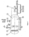
- a cylindrical tank 1 with domed bottoms, designed for pressures of 16, 25 or 40 bars.
- the level 2 regulator electric, is equipped with three magnetic switches: one for the minimum level, another for the maximum level and a third, located above that for the maximum level and connected to an alarm (sound signaling installation or bright).
- the auxiliary energy valve 3, electro-mechanical in Figure 1, pneumatic in Figure 2 and electromotive in Figure 3, receives from the level regulator 2 the impulse intended to stop the flow of condensate when its level in the cylindrical tank 1 reaches the minimum level provided or to allow the condensate to drain when its level in the tank 1 reaches the maximum provided.
- the minimum and maximum levels are adjusted as a function of the time necessary for the valve 3 to allow or stop the flow of the condensate and the quantity thereof.
- a level 4 visual controller a direct passage valve 5 to which heat consuming members are connected, a safety valve 6, a direct passage valve 7, a filter 8 against impurities, a valve 9 with direct passage, and on the bypass circuit a valve 10 with direct passage, a filter 11 against impurities, a non-return valve 12 and a valve 13 with direct passage.
- a drain valve 14 is arranged on the tank 1.
- the condensate separator operates on the principle that the flow of condensate through the outlet or condensing circuit is regulated by an auxiliary energy valve 3.
- the cylindrical tank 1 is connected via the valve 5 to all the heat consuming members which use steam as the heating fluid, of identical pressure. It is located below the level occupied by the heating bodies in the aforementioned organs.
- a vapor space is formed, at the same pressure as that of the heating bodies of the heat consuming members, and an aqueous space.
- the vapor transmits its latent heat and liquefies; the condensate thus formed passes into the tank 1.
- the electric level regulator 2 sends a pulse to the valve 3 which opens the passage to the condensate.
- regulator 2 sends a pulse to valve .3 which closes the condensate passage.
- the minimum level is defined so as to be placed above the condensate outlet pipe to eliminate the hysteresis phenomena of the valves and to prevent that the vapor being in the tank 1 can enter the condensate outlet pipe.
- the condensate in the tank 1, rising above the maximum level will activate the third magnetic switch, triggering 1 1 alarm.
- An audible or light signal will then warn the operator that it is necessary to open the valves 10 and 13 of the bypass circuit.
- the condensate separator can therefore operate manually, for example during the repair time of the automatic.
- tank 1 there is also the essential safety valve 6, according to the standards in force for pressure vessels and a level 4 visual controller allows the observation of the condensate level in tank 1.
- the condensate separator can be of three types, depending on the nature of the valve 3: electro-mechanical if the valve 3 is electromechanical (figure 1), pneumatic if the valve 3 is pneumatic (figure 2) and electromotorized if the valve 3 is electromotive (Figure 3).
Landscapes
- Engineering & Computer Science (AREA)
- General Engineering & Computer Science (AREA)
- Mechanical Engineering (AREA)
- Separation By Low-Temperature Treatments (AREA)
- Pipeline Systems (AREA)
Abstract
Description
Pratiquement toutes les industries qui utilisent la vapeur comme fluide chauffant, soit pour assurer des conditions de travail (chauffage des pièces), soit pour le déroulement des processus technologiques, sont confrontées avec le problème toujours présent de la condensation de la vapeur et du retour du condensat dans la chaudière. Ce phénomène est dû au fonctionnement incertain des séparateurs de condensat actuels qu'il s'agisse des séparations thermo-dynamiques ou des purgeurs, car ceux-ci ont réalisés pour fonctionner sans énergie d'appoint.Practically all industries which use steam as a heating fluid, either to ensure working conditions (heating of parts) or for the development of technological processes, are confronted with the ever present problem of condensation of steam and the return of condensate in the boiler. This phenomenon is due to the uncertain functioning of current condensate separators, whether they are thermodynamic separations or steam traps, because these have been designed to operate without additional energy.
Jusqu'à présent, par leur construction inappro- priée, les séparateurs de condensat laissaient partir la vapeur aussi dans le circuit de condensation, avant que celle-ci ait transmise, à un organe consommateur de chaleur toute sa chaleur latente, ce qui avait pour conséquence des grandes pertes de l'énergie thermique ainsi que des pertes de condensat à cause de l'évaporation.Until now, by their unsuitable construction, the condensate separators let the steam also leave in the condensing circuit, before this one transmitted, to an organ consuming heat all its latent heat, which had for consequence of large losses of thermal energy as well as losses of condensate due to evaporation.
La pose des séparateurs de condensat derrière chaque organe consommateur n'a fait qu'augmenter le nombre d'endroits où se perdent l'énergie thermique et le condensat, de même que la maintenance devenait chère et très souvent inefficace.The installation of condensate separators behind each consumer unit has only increased the number of places where thermal energy and condensate are lost, just as maintenance became expensive and very often ineffective.
Le séparateur de condensat exposé ci-après, évite les défauts cités ci-dessus en ne laissant passer dans le circuit de condensation que le condensat (c. à d. la phase liquide de la vapeur).The condensate separator set out below avoids the faults mentioned above by allowing only the condensate to pass through the condensing circuit (ie the liquid phase of the vapor).
La vapeur transmet ainsi toute sa chaleur latente à l'organe consommateur de chaleur.The vapor thus transmits all of its latent heat to the heat-consuming organ.
Ce séparateur comprend un réservoir, de préférence cylindrique, muni d'un régulateur de niveau, de préférence électrique, avec alarme, d'une vanne de vidange,avantageusement d'un contrôleur de niveau visuel et d'une soupape de se- curité. Le circuit d'entrée de la vapeur et du condensat, relié aux organes consommateurs de chaleur, est muni d'une vanne à passage direct. Sur le circuit de sortie du condensat, on trouve, asservie au régulateur de niveau, d'une part une vanne à énergie d'appoint précédée successivement d'une vanne à passage direct et d'un filtre contre les impuretés et suivie d'une vanne à passage direct, et d'autre-part, sur un circuit de contournement disposé en parallèle, successivement une vanne à passage direct, un filtre contre les impuretés, un clapet anti-retour et une vanne à passage direct.This separator comprises a tank, preferably cylindrical, provided with a level regulator, preferably electric, with alarm, a drain valve, advantageously a visual level controller and a safety valve. The steam and condensate inlet circuit, connected to the heat consuming components, is fitted with a direct flow valve. On the condensate outlet circuit, on the one hand, there is a back-up energy valve, successively preceded by a direct flow valve and an impurity filter, followed by a direct passage valve, and secondly, on a bypass circuit arranged in parallel, successively a direct passage valve, a filter against impurities, a non-return valve and a direct passage valve.
La vanne à énergie d'appoint arrête l'écoulement du condensat lorsque son niveau dans le réservoir atteint le niveau minimum prévu et permet l'écoulement de celui-ci quand son niveau atteint le niveau maximum prévu.The auxiliary energy valve stops the flow of condensate when its level in the tank reaches the minimum level provided and allows the flow of the latter when its level reaches the maximum level provided.
Cette vanne à énergie d'appoint peut-être aussi bien électro-magnétique que pneumatique ou électromotorisée.This back-up energy valve can be either electromagnetic, pneumatic or electromotive.
Les figures qui suivent,données à titre d'exemples, illustrent l'invention.
- La figure 1 est une vue en coupe longitudinale du séparateur de condensat du type électro-magnétique, où la vanne à appoint d'énergie est électro-magnétique.
- La figure 2 est une vue en coupe longitudinale du séparateur de condensat du type pneumatique, où la vanne à appoint d'énergie est pneumatique.
- La figure 3 est une vue en coupe longitudinale du séparateur de condensat du type électromotorisé, où la vanne à appoint d'énergie est électromotorisée.
- La figure 4 est une vue en coupe transversale du séparateur selon l'une quelconque des figures précédentes.
- Figure 1 is a longitudinal sectional view of the electro-magnetic type condensate separator, where the energy backup valve is electro-magnetic.
- Figure 2 is a longitudinal sectional view of the pneumatic type condensate separator, where the energy back-up valve is pneumatic.
- Figure 3 is a longitudinal sectional view of the electromotive type condensate separator, where the energy back-up valve is electromotive.
- Figure 4 is a cross-sectional view of the separator according to any of the preceding figures.
En références à ces figures, on a représenté un réservoir 1 cylindrique, à fonds bombés, conçu pour des pressions de 16, 25 ou 40 bars. Le régulateur de niveau 2, électrique, est équippé de trois interrupteurs magnétique : un pour le niveau minimum, un autre pour le niveau maximum et un troisième, situé au dessus de celui pour le niveau maximum et branché sur une alarme (installation de signalisation sonore ou lumineuse).Referring to these figures, there is shown a
La vanne à énergie d'appoint 3, électro-mécanique dans la figure 1, pneumatique dans la figure 2 et électromotorisée dans le figure 3, reçoit du régulateur de niveau 2 l'impulsion destinée à arrêter l'écoulement du condensat lorsque son niveau dans le réservoir cylindrique 1 atteint le niveau mimimum prévu ou à permettre l'écoulement du condensat quand son niveau dans le réservoir 1 atteint le maximum prévu. Le réglage des niveaux minimum et maximum est fait en fonction du temps nécessaire à la vanne 3 pour permettre ou arrêter l'écoulement du condensat et de la quantité de celui-ci.The
Sont représentés également : un contrôleur visuel de niveau 4, une vanne 5 à passage direct sur laquelle sont branchés des organes consommateurs de chaleur, une soupape de sécurité 6, une vanne 7 à passage direct, un filtre 8 contre les impuretés, une vanne 9 à passage direct, et sur le circuit de contournement une vanne 10 à passage direct, un filtre 11 contre les impurétés, un clapet anti-retour 12 et une vanne 13 à passage direct. Une vanne de vidange 14 est disposée sur le réservoir 1.Also shown: a
Le séparateur de condensat fonctionne suivant le principe que l'écoulement du condensat à travers le circuit de sortie ou de condensation est régularisé par une vanne 3 à énergie d'appoint. Le réservoir 1 cylindrique est relié par l'intermédiaire de la vanne 5 à tous les organes consommateurs de chaleur qui utilisent la vapeur comme fluide chauffant, de pression identique. Il est situé au dessous du niveau qu'occupent les corps chauffants dans les organes précités.The condensate separator operates on the principle that the flow of condensate through the outlet or condensing circuit is regulated by an
Dans le réservoir 1 se forment un espace de vapeur, à la même pression que celle des corps chauffants des organes consommateurs de chaleur, et un espace aqueux. Dans ces corps chauffants, la vapeur transmet sa chaleur latente et se liquéfie ; le condensat ainsi formé passe dans le réservoir 1. Lorsque le niveau de condensat atteint le niveau maximum, le régulateur de niveau 2 électrique envoie une impulsion à la vanne 3 qui ouvre le passage au condensat. Lorsque le niveau de condensat atteint le minimum, le régulateur 2 envoie une impulsion à la vanne .3 qui ferme le passage du condensat.In the tank 1 a vapor space is formed, at the same pressure as that of the heating bodies of the heat consuming members, and an aqueous space. In these heating bodies, the vapor transmits its latent heat and liquefies; the condensate thus formed passes into the
Le niveau minimum est défini de manière à être placé au dessus du conduit de sortie du condensat pour éliminer les phénomènes d'hystérésis des vannes et empêcher que la vapeur se trouvant dans le réservoir 1 puisse entrer dans le conduit de sortie du condensat.The minimum level is defined so as to be placed above the condensate outlet pipe to eliminate the hysteresis phenomena of the valves and to prevent that the vapor being in the
S'il advenait que la vanne 3 ne réagisse pas aux impulsions du régulateur de niveau 2, le condensat dans le réservoir 1, en montant au dessus de niveau maximum, actionnera le troisième interrupteur magnétique, déclanchant 11 alarme. Un signal sonore ou lumineux avertira alors l'opérateur qu'il est nécessaire d'ouvrir les vannes 10 et 13 du circuit de contournement. Le séparateur de condensat peut donc fonctionner en manuel, par exemple pendant le temps de réparation de l'automatique.If the
Sur le réservoir 1 se trouve aussi l'indispensable soupape de sécurité 6, selon les normes en vigueur pour les récipients sous pression et un contrôleur visuel de niveau 4 permet l'observation du niveau de condensat dans le réservoir 1.On
Le séparateur de condensat peut être de trois types, selon la nature de la vanne 3 : électro-mécanique si la vanne 3 est électromécanique (figure 1), pneumatique si la vanne 3 est pneumatique (figure 2) et électromotorisé si la vanne 3 est électromotorisée (figure 3).The condensate separator can be of three types, depending on the nature of the valve 3: electro-mechanical if the
Claims (5)
sur le circuit d'entrée de la vapeur et du condensat,
sur le circuit de sortie de condensat,
la vanne à énergie d'appoint (3) étant asservie au régulateur de niveau (2) de façon à arrêter l'écoulement du condensat lorsque son niveau dans le réservoir (1) atteint le niveau minimum prévu et à permettre l'écoulement du condensat quand son niveau atteint le maximun prévu.1. Condensate separator, characterized in that it comprises:
on the steam and condensate inlet circuit,
on the condensate outlet circuit,
the auxiliary energy valve (3) being slaved to the level regulator (2) so as to stop the flow of condensate when its level in the tank (1) reaches the minimum level provided and to allow the flow of condensate when its level reaches the maximum expected.
Applications Claiming Priority (2)
| Application Number | Priority Date | Filing Date | Title |
|---|---|---|---|
| YU2670/79 | 1979-11-01 | ||
| YU267079A YU267079A (en) | 1979-11-01 | 1979-11-01 | Condensate separator |
Publications (1)
| Publication Number | Publication Date |
|---|---|
| EP0028582A1 true EP0028582A1 (en) | 1981-05-13 |
Family
ID=25558518
Family Applications (1)
| Application Number | Title | Priority Date | Filing Date |
|---|---|---|---|
| EP80810322A Withdrawn EP0028582A1 (en) | 1979-11-01 | 1980-10-27 | Condensate separator |
Country Status (6)
| Country | Link |
|---|---|
| EP (1) | EP0028582A1 (en) |
| JP (1) | JPS57500302A (en) |
| BR (1) | BR8008899A (en) |
| DK (1) | DK273581A (en) |
| WO (1) | WO1981001322A1 (en) |
| YU (1) | YU267079A (en) |
Cited By (2)
| Publication number | Priority date | Publication date | Assignee | Title |
|---|---|---|---|---|
| EP0081826A2 (en) * | 1981-12-16 | 1983-06-22 | Koch, Berthold | Apparatus for removing condensate and the like from pressure systems |
| WO1998015771A1 (en) * | 1996-10-07 | 1998-04-16 | Filterwerk Mann+Hummel Gmbh | Device for recirculating condensates in gas flows |
Families Citing this family (1)
| Publication number | Priority date | Publication date | Assignee | Title |
|---|---|---|---|---|
| CN105965732B (en) * | 2016-07-06 | 2019-01-18 | 中策橡胶集团有限公司 | Tyre vulcanization hot plate steam pipework draining system and its application |
Citations (6)
| Publication number | Priority date | Publication date | Assignee | Title |
|---|---|---|---|---|
| US1701143A (en) * | 1922-01-11 | 1929-02-05 | Charles W E Clarke | Apparatus for utilizing drip in high-pressure steam systems |
| US2062672A (en) * | 1932-06-14 | 1936-12-01 | Swartwout Co | Drainage control |
| DE1042327B (en) * | 1955-01-17 | 1958-10-30 | Baelz & Sohn K G W | Device for regulating the flow of liquid in pipeline systems and the like like |
| US3572588A (en) * | 1969-04-03 | 1971-03-30 | Boiler Equipment And Controls | Condensate and heat recovery system |
| FR2234512A1 (en) * | 1973-06-20 | 1975-01-17 | Katsuji Fujiwara | |
| FR2304028A1 (en) * | 1975-03-13 | 1976-10-08 | Tech Pour Ind Et | Boiler condensate return system - uses pumped direct injection system with buffer tank and dump valve |
-
1979
- 1979-11-01 YU YU267079A patent/YU267079A/en unknown
-
1980
- 1980-10-27 WO PCT/CH1980/000129 patent/WO1981001322A1/en unknown
- 1980-10-27 JP JP50239680A patent/JPS57500302A/ja active Pending
- 1980-10-27 EP EP80810322A patent/EP0028582A1/en not_active Withdrawn
- 1980-10-27 BR BR8008899A patent/BR8008899A/en unknown
-
1981
- 1981-06-22 DK DK273581A patent/DK273581A/en not_active Application Discontinuation
Patent Citations (6)
| Publication number | Priority date | Publication date | Assignee | Title |
|---|---|---|---|---|
| US1701143A (en) * | 1922-01-11 | 1929-02-05 | Charles W E Clarke | Apparatus for utilizing drip in high-pressure steam systems |
| US2062672A (en) * | 1932-06-14 | 1936-12-01 | Swartwout Co | Drainage control |
| DE1042327B (en) * | 1955-01-17 | 1958-10-30 | Baelz & Sohn K G W | Device for regulating the flow of liquid in pipeline systems and the like like |
| US3572588A (en) * | 1969-04-03 | 1971-03-30 | Boiler Equipment And Controls | Condensate and heat recovery system |
| FR2234512A1 (en) * | 1973-06-20 | 1975-01-17 | Katsuji Fujiwara | |
| FR2304028A1 (en) * | 1975-03-13 | 1976-10-08 | Tech Pour Ind Et | Boiler condensate return system - uses pumped direct injection system with buffer tank and dump valve |
Cited By (3)
| Publication number | Priority date | Publication date | Assignee | Title |
|---|---|---|---|---|
| EP0081826A2 (en) * | 1981-12-16 | 1983-06-22 | Koch, Berthold | Apparatus for removing condensate and the like from pressure systems |
| EP0081826A3 (en) * | 1981-12-16 | 1984-10-03 | Koch, Berthold | Apparatus for removing condensate and the like from pressure systems |
| WO1998015771A1 (en) * | 1996-10-07 | 1998-04-16 | Filterwerk Mann+Hummel Gmbh | Device for recirculating condensates in gas flows |
Also Published As
| Publication number | Publication date |
|---|---|
| JPS57500302A (en) | 1982-02-18 |
| DK273581A (en) | 1981-06-22 |
| WO1981001322A1 (en) | 1981-05-14 |
| YU267079A (en) | 1984-12-31 |
| BR8008899A (en) | 1981-08-25 |
Similar Documents
| Publication | Publication Date | Title |
|---|---|---|
| FR2605088A1 (en) | POWER PLANT WITH WATER LEVEL REGULATION OF THE BOILER BODY | |
| EP0028582A1 (en) | Condensate separator | |
| EP1009951B1 (en) | Method for operating a boiler with forced circulation and boiler for its implementation | |
| US5530987A (en) | Condensate drain controller | |
| KR820000454B1 (en) | Bilge water disposal method including oil recovery means | |
| JP6790458B2 (en) | Gas engine cogeneration system | |
| JP3286023B2 (en) | Waste heat recovery boiler condensate water supply protection system | |
| JPH06257962A (en) | Heater drain discharging device | |
| JPS60256704A (en) | Inspection device for completion of drainage | |
| DE650090C (en) | Water tube boiler with coiled tubes and a circulation pump that is independent of the boiler feed device | |
| SU581316A1 (en) | System for regulating steam pressure in steam-turbine plant | |
| JPS6018900B2 (en) | Bath water circulation/water heater heating control device | |
| US1602160A (en) | Automatic safety valve | |
| JPH025261B2 (en) | ||
| SU875181A2 (en) | Intermediate separator-steam superheater | |
| BE857688A (en) | FORCED CIRCULATION STEAM GENERATOR | |
| SU564488A1 (en) | Method for starting direct-flow boiler unit | |
| BE570659A (en) | ||
| FR2506907A1 (en) | Energy recuperator for hot water boiler - has heat extracted from flue during burner operation to inlet water circulated by pump | |
| JPH0138463Y2 (en) | ||
| JPS6028921Y2 (en) | solar water heater | |
| JPS6058367B2 (en) | Hot water supply device | |
| FR2528952A1 (en) | Heat economiser for liq. or gas fired central heating boiler - has thermostatically controlled motor driven shutters which selectively channel smoke through tubes connected to water circulation system | |
| FR2770211A1 (en) | Liquid sewage treatment | |
| BE889228A (en) | PROCESS AND DEVICE FOR RECOVERING SMOKE GAS HEAT |
Legal Events
| Date | Code | Title | Description |
|---|---|---|---|
| PUAI | Public reference made under article 153(3) epc to a published international application that has entered the european phase |
Free format text: ORIGINAL CODE: 0009012 |
|
| AK | Designated contracting states |
Designated state(s): AT BE CH DE FR GB IT LI LU NL SE |
|
| 17P | Request for examination filed |
Effective date: 19811022 |
|
| STAA | Information on the status of an ep patent application or granted ep patent |
Free format text: STATUS: THE APPLICATION IS DEEMED TO BE WITHDRAWN |
|
| 18D | Application deemed to be withdrawn |
Effective date: 19831213 |