EP0028552A1 - Vehicle braking regulation systems, particularly for aircraft - Google Patents
Vehicle braking regulation systems, particularly for aircraft Download PDFInfo
- Publication number
- EP0028552A1 EP0028552A1 EP80401459A EP80401459A EP0028552A1 EP 0028552 A1 EP0028552 A1 EP 0028552A1 EP 80401459 A EP80401459 A EP 80401459A EP 80401459 A EP80401459 A EP 80401459A EP 0028552 A1 EP0028552 A1 EP 0028552A1
- Authority
- EP
- European Patent Office
- Prior art keywords
- speed
- braked wheel
- brake release
- cycle
- braking
- Prior art date
- Legal status (The legal status is an assumption and is not a legal conclusion. Google has not performed a legal analysis and makes no representation as to the accuracy of the status listed.)
- Withdrawn
Links
Images

Classifications
-
- B—PERFORMING OPERATIONS; TRANSPORTING
- B60—VEHICLES IN GENERAL
- B60T—VEHICLE BRAKE CONTROL SYSTEMS OR PARTS THEREOF; BRAKE CONTROL SYSTEMS OR PARTS THEREOF, IN GENERAL; ARRANGEMENT OF BRAKING ELEMENTS ON VEHICLES IN GENERAL; PORTABLE DEVICES FOR PREVENTING UNWANTED MOVEMENT OF VEHICLES; VEHICLE MODIFICATIONS TO FACILITATE COOLING OF BRAKES
- B60T8/00—Arrangements for adjusting wheel-braking force to meet varying vehicular or ground-surface conditions, e.g. limiting or varying distribution of braking force
- B60T8/17—Using electrical or electronic regulation means to control braking
- B60T8/1701—Braking or traction control means specially adapted for particular types of vehicles
- B60T8/1703—Braking or traction control means specially adapted for particular types of vehicles for aircrafts
-
- B—PERFORMING OPERATIONS; TRANSPORTING
- B60—VEHICLES IN GENERAL
- B60T—VEHICLE BRAKE CONTROL SYSTEMS OR PARTS THEREOF; BRAKE CONTROL SYSTEMS OR PARTS THEREOF, IN GENERAL; ARRANGEMENT OF BRAKING ELEMENTS ON VEHICLES IN GENERAL; PORTABLE DEVICES FOR PREVENTING UNWANTED MOVEMENT OF VEHICLES; VEHICLE MODIFICATIONS TO FACILITATE COOLING OF BRAKES
- B60T8/00—Arrangements for adjusting wheel-braking force to meet varying vehicular or ground-surface conditions, e.g. limiting or varying distribution of braking force
- B60T8/17—Using electrical or electronic regulation means to control braking
- B60T8/172—Determining control parameters used in the regulation, e.g. by calculations involving measured or detected parameters
-
- B—PERFORMING OPERATIONS; TRANSPORTING
- B64—AIRCRAFT; AVIATION; COSMONAUTICS
- B64C—AEROPLANES; HELICOPTERS
- B64C25/00—Alighting gear
- B64C25/32—Alighting gear characterised by elements which contact the ground or similar surface
- B64C25/42—Arrangement or adaptation of brakes
- B64C25/44—Actuating mechanisms
- B64C25/46—Brake regulators for preventing skidding or aircraft somersaulting
Definitions
- the invention relates to improvements made to brake regulation installations for vehicles called to run on the ground, in particular for aerodynes provided with a hydraulically controlled braking installation.
- the regulation chain of these installations includes means delivering signals representative of the actual speed of the vehicle, by copying the speed of an unbraked wheel, or by integration of analog signals representative of the acceleration of the vehicle, detected by a accelerometer, for example with inertia, mounted on the vehicle and arranged to measure its longitudinal accelerations, as well as a sensor delivering signals representative of the speed of a braked wheel, in this case a direct current tachometer generator, delivering an analog electric voltage proportional to the speed of rotation, an analog computer making it possible to compare the speed of the braked wheel to that of the vehicle, to calculate a setpoint slip as being the adequate slip to be produced, to develop, consequently, a signal representative of a setpoint speed, on which the speed of the braked wheel must be controlled by the installation, to compare the speed signals of the braked wheel and the set speed to develop a control order for a braking control member, generally an electro-hydraulic interface, capable of actuating the vehicle brakes in proportion to the braking torque.
- the electro-hydraulic interface is most often a pressure-controlled servo-valve, delivering, in the operating line which connects it to the brakes, a pressure which is proportional to the electric control current coming from the analog computer. All the devices that such regulation installations include are essentially analog, their output function being continuous and proportional to their input function. Recent developments in technology in the field of electronics now allow the creation of digital computers fulfilling the same functions as those devolved to analog computers, conventionally used in known brake control installations.
- a regulation installation is characterized in that the sensor delivering signals representative of the speed of a braked wheel is a pulse generator, which are transmitted to the computer, of the type digital, measuring the speed of the braked wheel by relative counting of the number of pulses and the number of time units determined by a clock, and controlling the braking control member in "all or nothing" mode, according to a function of direct transfer such that the rest position of the control member is not to send a brake release order when the speed of the braked wheel is greater than the set speed, and that the active position of the control member is to send a brake release command when the speed of the braked wheel is lower than the set speed.
- the computer can take speed into account, either by counting the number of pulses per unit of time, or by counting the number of units of time between two pulses, the unit of time being chosen sufficiently short so that at the maximum wheel speed there are always several units of time between two pulses.
- the calctilator controls the brake control member by one. series of cycles succeeding each other at a predetermined rate, and, at each start of the cycle, a brake release order is created, the duration of which is zero if brake release is not necessary, and the duration of which is that of a cycle if total brake release is necessary.
- each cycle is divided into several equal parts, the duration of the brake release order created at the start of the cycle being that of a fraction of a cycle, corresponding to a whole number, determined by the computer, of parts of a cycle, if a partial brake release is necessary, the duration of the brake release order being, as before, zero or equal to that of the cycle if respectively a brake release is not or is necessary.
- the anticipation of the piloting of the brake control member, compensating for the response delays of the latter and of the brakes in particular, is achieved by adding to the direct transfer function, a weighted function proportional to the acceleration of the braked wheel, as well as possibly a weighted function proportional to the second derivative of the speed of the braked wheel as a function of time.
- the braking control member is an electro-hydraulic interface, which delivers to the hydraulically controlled brakes an actuating pressure proportional to the braking torque.
- the variation of pressure in the brakes supposes the variation of volume of oil in the hydraulic cylinders of the brakes, which is usually obtained by means of a servo-valve controlled in pressure, which regulates the quantity oil sent to the brakes so that the final brake actuation pressure corresponds to the electric current coming from the computer and supplying the electric stage of the servo-valve, the value of this electric current being, in known prior installations, generally adjusted analogically, that is to say that the current can take all values between zero and maximum.
- a servo valve controlled by flow the structure of which is a little simpler than that of the previous type, is also usable, its characteristic of progressivity not necessarily being used, but the required performance remains assured.
- the braking control member is a fast solenoid valve delivering to the hydraulically controlled brakes an actuating pressure proportional to the braking torque, and controlled in "all or nothing" "by the fast solenoid valve, itself electrically controlled” all or nothing "by the computer.
- optical sensors transforming light pulses into electrical signals, either at the level of the sensor itself, or transported by optical fibers, to an appropriate interface at the input of the regulator described below.
- the sensors 1 and 2 are, in all cases, connected to the input interface 9 of a digital computer 10, ensuring the measurement of the speed of the braked wheel V R and of the real speed of the assimilated aerodyne VA at the unbraked wheel speed 3, the determination of the setpoint slip GC in a manner corresponding to that considered in the earlier patents cited above, and the determination of the setpoint speed Vc on which the speed of the wheel is controlled braked V R , then the power control of the solenoid valve 6.
- the input interface 9 transforms the signals emitted by the sensors 1 and 2 in digital calculation values which can be used by the digital computer 10. The latter can calculate the speeds of the vehicle VA and of the braked wheel V R in two different ways.
- the comparison between the reference speed V C and the speed of the braked wheel V R is then carried out in the comparator block 12, which generates an error signal ⁇ , communicated to the adder 13, itself connected to the interface of output or command 14, ensuring the transformation of digital orders received from the adder 13 in electrical orders sent to the piloting stage of the rapid electrovalve 6.
- the latter is piloted in "all or nothing", so that the quantity of hydraulic oil withdrawn or added to the circuit braking is proportional respectively to the opening time or the closing time of the solenoid valve 6.
- the braking conditions vary from one moment to the next, either due to noise on the line measuring the speed of the braked wheel (tachometric generator noise), or variations brutal speed, due to local accidents of contact between the tire of the braked wheel and the track, etc.
- the rapid and successive variations of con braking conditions amplified by the regulation chain, cause the pressure; which, theoretically, could be constant, or slightly variable, is in fact a succession of increases and decreases in pressure, with more or less significant level variations, around a mean value.
- the operation of the proposed digital servo is therefore very similar to that of known analog servo. It also has the advantage that the frequency of pressure variations is no longer random, but determined, and that it can be chosen according to certain criteria, in particular such that it has no influence on the own vibrations of the landing gear leg of the aerodyne.
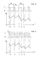
- the evolution by successive increase and decrease in the pressure P over time is controlled by a series of cycles which follow one another at a predetermined frequency suitable for the application envisaged, ie for example 50 Hz.
- the duration D of a cycle is therefore 20 ms.
- the rest position R of the control interface 14 is not to send an electric brake release order to the solenoid valve 6, while the working position T is to send an electric brake release order, in the form d '' an electric current of suitable intensity flowing through the coil of the control stage of the solenoid valve 6.
- a brake release order is created, but this order will be of zero duration if brake release is not necessary. If a complete brake release is required, the duration of this order will be equal to that of a cycle, i.e. 20 ms. If a partial brake release is necessary, the duration of this order will be limited to a portion of the duration of a cycle, variable between 0 and 20 ms, and determined by the computer 10. This duration is not continuously variable, but it represents an integer fraction of the total duration of the cycle, which is divided into several equal parts, for example four parts of 5 ms. Thus, during the first cycle D1 of a sequence considered in FIG.
- a partial brake release order for a quarter of a cycle commands a pressure drop between times t1 and t2, followed by an increase in pressure during the three remaining quarters of the cycle, between instants t2 and t3, this last instant corresponding to the start of the next cycle D2, identical to the first, while in the third cycle D3, a partial brake release order the duration of which is half a cycle, commands a pressure drop between times t4 and t5, followed by an increase during the second half of the cycle, from t5 to t6.
- the evolution by successive variations of the pressure P as a function of time is also controlled by a series of cycles succeeding each other at a predetermined frequency, greater than that chosen in FIG. 2.
- each cycle is completely performed in full brake release or full braking, the rest R and working positions T of the control interface 14 being the same as before.
- the result will be identical to the previous one if the support frequency in this example is 200 Hz, for identical braking conditions.
- a brake release order in the first cycle d of duration equal to 5 ms and commanding a pressure drop, will be followed by three braking orders, in the following three cycles, commanding an increase in pressure, as represented respectively between the instants t1 and t2, and t2 and t3.
- the duration of a pressure variation cycle must correspond to the duration of at least one, but preferably several calculation cycles of the digital computer 10, since it is necessary to control the solenoid valve 6 at a frequency that it is able to accept.
- the principle of the regulation installation is to control the speed of the braked wheel V R to a set speed Vc which can be a simple percentage of the speed of the aerodyne VA, assimilated to the speed of the unbraked wheel.
- a first solution is to perform the same transfer function in electronics as that performed in analog electronics.
- a second solution is to use a suitably amplified direct transfer function.
- the direct transfer function consists in not issuing a brake release order if the speed of the braked wheel is higher than the set speed, and in issuing a brake release order in the opposite case.
- This anticipation will be carried out taking into account the variation in the speed of the braked wheel, and therefore its acceleration.
- the computer 10 therefore develops, in a block 15, a function B calculated from the acceleration, with a level all the higher as the acceleration will be high, and this function B, suitably weighted, is added to the summary. tor 13 with direct function A, also weighted, developed in comparator 12.
- Vn and Vn-1 are the speeds at these instants t n and t n-1 and ⁇ n l acceleration at time tn.
- This function C is developed in a block 16 of the computer 10 from the second derivative and, after weighting, is added to the first two functions in the summator 13.
- a function D developed in block 17, to limit the successive number of braking or brake release orders, taking account of previous orders , is added, after weighting, to the other functions in the summator 13.
- a function D makes it possible, for example, to systematically give a brake release order if such an order has not been given during the ten preceding cycles, in order to limit the slope of the pressure build-up in the brakes.
- a weighted function E developed in block 18, in order to filter the particular frequencies to be damped, so as not to resonate with an external periodic phenomenon, such as the vibration of the brakes or the natural frequency of the undercarriage.
- the resulting command function F will therefore be the sum of the preceding functions: and the pressure in the brakes will result from the control of the fast solenoid valve 6 by this function F, through the control interface 14.
- the determination of the vehicle speed is not limited to the solution which consists in assimilating to it the speed of an unbraked wheel, but it is entirely possible to calculate the speed of the vehicle by any means corresponding, in digital technology, to means known in analog technology, for example by integration of a signal from a digital accelerometer. It is obvious that the brake regulating installation which has just been described in association with hydraulically controlled brakes can be adapted to brakes controlled by another means, for example by gas pressure or by electric current. , without departing from the scope of the invention.
- a braking regulation installation equipped with digital electronics, makes it easier to measure speeds, by means of a sensor of the pulse generator type, of simpler structure than that sensors used in analog control chains, such as tachogenerators, and therefore more reliable than the latter.
- digital electronics allows the use of an electro-hydraulic control interface, such as a fast solenoid valve, piloted in "all or nothing", with a simple, reliable structure, not very sensitive to pollution and little expensive, unlike the servo-valves used in the context of analog control chains which are certainly efficient, but of a delicate implementation.
- a digital regulation chain according to the invention makes it possible, by itself, to carry out easily and without additional cost, the tests proving necessary to verify the good operating condition of the braking installation.
- the braking installation according to the invention has many decisive advantages over the installations of the prior art.
Abstract
Description
L'invention concerne des perfectionnements apportés aux installations de régulation de freinage pour véhicules appelés à rouler sur le sol, en particulier pour des aérodynes munis d'une installation de freinage à commande hydraulique..The invention relates to improvements made to brake regulation installations for vehicles called to run on the ground, in particular for aerodynes provided with a hydraulically controlled braking installation.
Il est déjà connu des brevets français n° 1.378.958, n° 1.407..168 et du premier additif d ce dernier, n° 86.491, des installations de régulation de freinage à commande hydraulique, notamment pour trains d'atterrissage d'aérodynes, permettant d'asservir le glissement d'une roue freinée à une valeur déterminée par rapport a la vitesse qu'elle aurait eue en l'absence de freinage, c'est-à-dire en fait par rapport à la vitesse du véhicule support.It is already known from French patents n ° 1.378.958, n ° 1.407..168 and the first additive of the latter, n ° 86.491, brake control systems with hydraulic control, in particular for landing gear of aerodynes , allowing the slipping of a braked wheel to be controlled at a value determined with respect to the speed it would have had in the absence of braking, that is to say in fact with respect to the speed of the support vehicle .
La chaîne de régulation de ces installations comprend des moyens délivrant des signaux représentatifs de la vitesse réelle du véhicule, par recopie de la vitesse d'une roue non freinée, ou par intégration de signaux analogiques représentatifs de l'accélération du véhicule, décelée par un accéléromètre, par exemple à inertie, monté sur le véhicule et agencé de façon à mesurer ses accélérations longitudinales, ainsi qu'un capteur délivrant des signaux représentatifs de la vitesse d'une roue freinée, en l'occurrence une génératrice tachymétrique à courant continu, délivrant une tension électrique analogique proportionnelle à la vitesse de rotation, un calculateur analogique permettant de comparer la vitesse de la roue freinée à celle du véhicule, de calculer un glissement de consigne comme étant le glissement adéquat à réali ser, d'élaborer, en conséquence, un signal représentatif d'une vitesse de consigne, sur laquelle la vitesse de la roue freinée doit être asservie par l'installation, de comparer les signaux de vitesse de la roue freinée et de la vitesse de consigne pour élaborer un ordre de pilotage d'un organe de commande de freinage, en général une imterface électro-hydraulique, susceptible d'actionner les freins du véhicule proportionnellement au couple de freinage. L'interface électro-hydraulique est le plus souvent une servo-valve asservie en pression, délivrant, dans la conduite d'utilisation qui la relie aux freins, une pression qui est proportionnelle au courant électrique de commande provenant du calculateur analogique. Tous les appareils que comprennent de telles installations de régulation sont essentiellement analogiques, leur fonction de sortie étant continue et proportionnelle à leur fonction d'éntrée. Les récentes évolutions de la technologie dans le domaine de l'électronique permettent maintenant la réalisation de calculateurs numériques remplissant les mêmes fonctions que celles dévolues aux calculateurs analogiques, classiquement utilisés dans les installations de régulation de freinage connues.The regulation chain of these installations includes means delivering signals representative of the actual speed of the vehicle, by copying the speed of an unbraked wheel, or by integration of analog signals representative of the acceleration of the vehicle, detected by a accelerometer, for example with inertia, mounted on the vehicle and arranged to measure its longitudinal accelerations, as well as a sensor delivering signals representative of the speed of a braked wheel, in this case a direct current tachometer generator, delivering an analog electric voltage proportional to the speed of rotation, an analog computer making it possible to compare the speed of the braked wheel to that of the vehicle, to calculate a setpoint slip as being the adequate slip to be produced, to develop, consequently, a signal representative of a setpoint speed, on which the speed of the braked wheel must be controlled by the installation, to compare the speed signals of the braked wheel and the set speed to develop a control order for a braking control member, generally an electro-hydraulic interface, capable of actuating the vehicle brakes in proportion to the braking torque. The electro-hydraulic interface is most often a pressure-controlled servo-valve, delivering, in the operating line which connects it to the brakes, a pressure which is proportional to the electric control current coming from the analog computer. All the devices that such regulation installations include are essentially analog, their output function being continuous and proportional to their input function. Recent developments in technology in the field of electronics now allow the creation of digital computers fulfilling the same functions as those devolved to analog computers, conventionally used in known brake control installations.
De plus, on sait également réaliser des électrovalves hydrauliques rapides, susceptibles d'être pilotées par un calculateur numérique, et de répondre convenablement à une excitation de commande d'une fréquence notablement supérieure à 50 Hz, voire même à 100 Hz, en faisant varier leur temps d'ouverture par rapport au temps de fermeture, pour moduler en "tout ou rien" la pression dans un circuit hydraulique situé en aval de l'électrovalve rapide. Il est apparu intéressant de profiter des nouvelles possibilités ainsi offertes pour concevoir des installations de régulation de freinage entièrement numériques, sans se contenter de la solution intermédiaire qui consisterait à remplacer le calculateur électronique analogique des installations connues par un calculateur numérique assurant la même fonction, mais avec l'adjonction, à l'entrée et à la sortie du calculateur, de convertisseurs de signaux analogiques en signaux numériques.In addition, it is also known to produce rapid hydraulic solenoid valves, capable of being controlled by a digital computer, and to respond appropriately to a control excitation of a frequency notably greater than 50 Hz, or even at 100 Hz, by varying their opening time relative to the closing time, to modulate "all or nothing" the pressure in a hydraulic circuit located downstream of the fast solenoid valve. It appeared interesting to take advantage of the new possibilities thus offered to design fully digital brake control installations, without being satisfied with the intermediate solution which would consist in replacing the analog electronic computer of known installations by a digital computer ensuring the same function, but with the addition, at the input and output of the computer, of converters from analog signals to digital signals.
Dans le cas particulier d'une installation dans laquelle la commande du freinage est hydraulique, on se propose, de plus, selon l'invention, d'obtenir au moyen d'une installation entièrement numérique, un pilotage en pression très proche de celui obtenu au moyen d'installations analogiques, grâce à l'affaiblissement de la réponse hydraulique d'une électrovalve rapide par rapport à sa commande électrique, à partir d'une certaine fréquence d'excitation, en augmentant ou en abaissant le niveau de pression selon que l'on privilégie le temps d'ouverture par rapport au temps de fermeture ou inversement. A cet effet, une installation de régulation selon l'invention se caractérise en ce que le capteur délivrant des signaux représentatifs de la vitesse d'une roue freinée est un générateur d'impulsions, lesquelles sont transmises au calculateur, de type numérique, mesurant la vitesse de la roue freinée par comptage relatif du nombre d'impulsions et du nombre d'unités de temps déterminées par une horloge, et pilotant l'organe de commande de freinage en "tout ou rien", selon une fonction de transfert directe telle que la position de repos de l'organe de commande est de ne pas envoyer d'ordre de défreinage lorsque la vitesse de la roue freinée est supérieure à la vitesse de consigne, et que la position active de l'organe de commande est d'envoyer un ordre de défreinage lorsque la vitesse de la roue freinée est inférieure à la vitesse de consigne.In the particular case of an installation in which the braking control is hydraulic, it is further proposed, according to the invention, to obtain by means of an entirely digital installation, pressure control very close to that obtained by means of analogical installations, thanks to the weakening of the hydraulic response of a fast solenoid valve with respect to its electric control, from a certain excitation frequency, by increasing or decreasing the pressure level according to whether the opening time is favored over the closing time or vice versa. To this end, a regulation installation according to the invention is characterized in that the sensor delivering signals representative of the speed of a braked wheel is a pulse generator, which are transmitted to the computer, of the type digital, measuring the speed of the braked wheel by relative counting of the number of pulses and the number of time units determined by a clock, and controlling the braking control member in "all or nothing" mode, according to a function of direct transfer such that the rest position of the control member is not to send a brake release order when the speed of the braked wheel is greater than the set speed, and that the active position of the control member is to send a brake release command when the speed of the braked wheel is lower than the set speed.
Le calculateur peut prendre en compte la vitesse, soit par comptage du nombre d'impulsions par unité de temps, soit par comptage du nombre d'unités de temps entre deux impulsions, l'unité de temps étant choisie suffisamment courte pour qu'à la vitesse de rotation maximale de roues il y ait toujours plusieurs unités de temps entre deux impulsions. De plus, le calctila- teur pilote l'organe de commande dé freinage par une . suite de cycles se succédant à une cadence prédéterminée, et, à chaque début de cycle, un ordre de défreinage est créé, dont la durée est nulle si un défreinage n'est pas nécessaire, et dont la durée est celle d'un cycle si un défreinage total est nécessaire.The computer can take speed into account, either by counting the number of pulses per unit of time, or by counting the number of units of time between two pulses, the unit of time being chosen sufficiently short so that at the maximum wheel speed there are always several units of time between two pulses. In addition, the calctilator controls the brake control member by one. series of cycles succeeding each other at a predetermined rate, and, at each start of the cycle, a brake release order is created, the duration of which is zero if brake release is not necessary, and the duration of which is that of a cycle if total brake release is necessary.
Dans une autre réalisation, pour laquelle chaque cycle de la suite sera plus long que les cycles évoqués ci-dessus, chaque cycle est partagé en plusieurs parties égales, la durée de.l'ordre de défreinage créé au début du cycle étant celle d'une fraction de cycle, correspondant à un nombre entier, déterminé par le calculateur, de parties de cycle, si un défreinage partiel est nécessaire, 1a durée de l'ordre de défreinage étant, comme précédemment, nulle ou égale à celle du cycle si respectivement un défreinage n'est pas ou est nécessaire.In another embodiment, for which each cycle of the sequence will be longer than the cycles mentioned above, each cycle is divided into several equal parts, the duration of the brake release order created at the start of the cycle being that of a fraction of a cycle, corresponding to a whole number, determined by the computer, of parts of a cycle, if a partial brake release is necessary, the duration of the brake release order being, as before, zero or equal to that of the cycle if respectively a brake release is not or is necessary.
De préférence, l'anticipation du pilotage de l'organe de commande de freinage, compensant les retards de réponse de ce dernier et des freins notamment, est réalisée en ajoutant à la fonction de transfert directe, une fonction pondérée proportionnelle à l'accélération de la roue freinée, ainsi, éventuellement, qu'une fonction pondérée proportionnelle à la dérivée seconde de la vitesse de la roue freinée en fonction du temps.Preferably, the anticipation of the piloting of the brake control member, compensating for the response delays of the latter and of the brakes in particular, is achieved by adding to the direct transfer function, a weighted function proportional to the acceleration of the braked wheel, as well as possibly a weighted function proportional to the second derivative of the speed of the braked wheel as a function of time.
Afin d'éviter les variations trop brutales du couple de freinage, en particulier les augmentations de couple, il peut s'avérer nécessaire d'ajouter également à la fonction directe une fonction pondérée limitant le nombre de cycles successifs se déroulant sans ordre de défreinage, compte tenu des ordres antérieurs. Dans un grand nombre d'installations connues de régulation de freinage, l'organe de commande du freinage est une interface électro-hydraulique, qui délivre aux freins à commande hydraulique une pression d'actionnement proportionnelle au couple de freinage. Dans les installations de ce type, la variation de pression dans les freins suppose la variation de volume d'huile dans les cyclindres hydrauliques des freins, ce qui est habituellement obtenu au moyen d'une servo-valve asservie en pression, qui régule la quantité d'huile envoyée aux freins de manière à ce que la pression finale d'actionnement des freins corresponde au courant électrique en provenance du calculateur et alimentant 1'étage électrique de la servo-valve, la valeur de ce courant électrique étant, dans les installations antérieures connues, généralement réglée de façon analogique, c'est-à-dire que le courant peut prendre toutes les valeurs entre zéro et le maximum.In order to avoid excessively sudden variations in braking torque, in particular increases in torque, it may prove necessary to also add to the direct function a weighted function limiting the number of successive cycles taking place without brake release order, taking into account previous orders. In a large number of known braking regulation installations, the braking control member is an electro-hydraulic interface, which delivers to the hydraulically controlled brakes an actuating pressure proportional to the braking torque. In installations of this type, the variation of pressure in the brakes supposes the variation of volume of oil in the hydraulic cylinders of the brakes, which is usually obtained by means of a servo-valve controlled in pressure, which regulates the quantity oil sent to the brakes so that the final brake actuation pressure corresponds to the electric current coming from the computer and supplying the electric stage of the servo-valve, the value of this electric current being, in known prior installations, generally adjusted analogically, that is to say that the current can take all values between zero and maximum.
L'utilisation d'une telle servo-valve asservie en pression, dans une installation selon l'invention, est tout à fait possible, mais elle se présente toutefois cbmme une interface électro-hydraulique d'une inutile complexité.The use of such a pressure-controlled servo-valve, in an installation according to the invention, is entirely possible, but it nevertheless presents itself as an electro-hydraulic interface of unnecessary complexity.
Une servo-valve asservie en débit, dont la structure est un peu plus simple que celle du type précédent, est également utilisable, sa caractéristique de progressivité n'étant pas forcément utilisée, mais les performances requises restent assurées.A servo valve controlled by flow, the structure of which is a little simpler than that of the previous type, is also usable, its characteristic of progressivity not necessarily being used, but the required performance remains assured.
Dans une forme préférée de réalisation de l'installation selon l'invention, l'organe de commande de freinage est une électrovalve rapide délivrant aux freins à commande hydraulique une pression d'actionnement proportionnelle au couple de freinage, et commandée en "tout ou rien" par l'électrovalve rapide, elle-même pilotée électriquement en "tout ou rien" par le calculateur.In a preferred embodiment of the installation according to the invention, the braking control member is a fast solenoid valve delivering to the hydraulically controlled brakes an actuating pressure proportional to the braking torque, and controlled in "all or nothing" "by the fast solenoid valve, itself electrically controlled" all or nothing "by the computer.
L'invention sera mieux comprise à l'aide de l'exemple particulier de réalisation, qui sera à présent décrit, à titre non limitatif, en référence aux figures annexées dans lesquelles :
- - la figure 1 représente une vue schématique d'une installations de régulation de freinage à commande hydraulique pour train d'atterrissage d'aérodyne.
- - la figure 2 représente l'évolution en parallèle de l'ordre électrique de pilotage'de l'organe de commande de freinage, en l'occurrence une électrovalve rapide, et de la pression hydraulique dans les freins, en fonction du temps, dans une installation selon la figure 1 et selon un premier mode d'obtention de cet ordre électrique de pilotage.
- - et la figure 3 représente, de façon analogue, l'évolution des mêmes paramètres selon un second mode d'obtention de l'ordre électrique de pilotage. En référence à la figure 1, l'installation de régulation de freinage comprend des capteurs 1 et 2, montés respectivement sur l'atterrisseur avant et sur l'un des atterrisseurs principaux d'un aérodyne, et constitués sous la forme de générateurs de signaux alternatifs, pouvant être de forme sinusoïdale, tra- pézoîdale, rectangulaire ou triangulaire, et désignés ci-après comme étant des impulsions, représentatives respectivement de la vitesse de la roue 3 ou de l'une des roues avant, non freinée, de l'àérodyne, et de la vitesse de la
roue 4 ou de l'une des roues de l'atterrisseur principal, susceptible d'être freinée grâce auxfreins 5 à commande hydraulique, mis sous pression par l'intermédiaire d'une électrovalve rapide 6 reliée à un circuit hydraulique embarqué sur l'aérodyne par la conduite d'alimentation 7, et la conduite de retour 8 reliée à une bâche ou réservoir du circuit hydraulique. - Le nombre des impulsions émises par les capteurs 1 ou 2, par tour de roue 3 ou 4, peut être quelconque, mais dans l'application à l'équipement des aérodynes qui nous intéresse, ce nombre est avantageusement de l'ordre de 50 impulsions par mètre de circonférence des roues 3 et 4, soit environ 200 par révolution pour une roue d'avion civil. La valeur crête à crête des impulsions n'a pas d'influence directe sur le fonctionnement de l'installation, mais elle doit cependant être compatible avec les possibilités de traitements des circuits électroniques décrits ci-après. La technologie des capteurs 1 et 2 est indifférente, mais, de préférence, les impulsions sont émises sous la forme de signaux électriques, les capteurs 1
èt 2 étant par exemple des capteurs à induction ou à aimant permanent d'un type bien connu en soit.
- - Figure 1 shows a schematic view of a brake control installation with hydraulic control for landing gear of an aerodyne.
- - Figure 2 shows the parallel evolution of the electrical order of piloting of the braking control member, in this case a fast solenoid valve, and of the hydraulic pressure in the brakes, as a function of time, in an installation according to FIG. 1 and according to a first method of obtaining this electrical control command.
- - And Figure 3 shows, analogously, the evolution of the same parameters according to a second mode of obtaining the electrical control command. With reference to FIG. 1, the brake control installation comprises
sensors 1 and 2, mounted respectively on the front undercarriage and on one of the main undercarriages of an aerodyne, and constituted in the form of signal generators alternating, which may be sinusoidal, trapezoidal, rectangular or triangular, and hereinafter designated as pulses, representative respectively of the speed of the wheel 3 or of one of the front wheels, unbraked, of the aerodyne, and of the speed of thewheel 4 or of one of the wheels of the main undercarriage, capable of being braked by means of thebrakes 5 with hydraulic control, pressurized by means of a fast solenoid valve 6 connected to a hydraulic circuit on board the aerodyne by the supply line 7, and the return line 8 connected to a tank or tank of the hydraulic circuit. - The number of pulses emitted by
sensors 1 or 2, perwheel revolution 3 or 4, can be any, but in the application to the equipment of aerodynes which interests us, this number is advantageously of the order of 50 pulses per meter of circumference of thewheels 3 and 4, or approximately 200 per revolution for a civil aircraft wheel. The peak-to-peak value of the pulses has no direct influence on the operation of the installation, but it must however be compatible with the processing possibilities of the electronic circuits described below. The technology ofsensors 1 and 2 is indifferent, but, preferably, the pulses are emitted in the form of electrical signals, thesensors 1 and 2 being for example induction or permanent magnet sensors of a type well known in itself. .
On peut également utiliser des capteurs optiques transformant des impulsions lumineuses en signaux électriques, soit au niveau du capteur lui-même, soit transportées par fibres optiques, jusqu'à une interface appropriée à l'entrée du régulateur décrit ci-après.It is also possible to use optical sensors transforming light pulses into electrical signals, either at the level of the sensor itself, or transported by optical fibers, to an appropriate interface at the input of the regulator described below.
Les capteurs 1 et 2 sont, dans tous les cas, reliés à l'interface d'entrée 9 d'un calculateur numérique 10, assurant la mesure de vitesse de la roue freinée VR et de la vitesse réelle de l'aérodyne VA assimilée à la vitesse de roue non freinée 3, la détermination du glissement de consigne GCd'une façon correspondant à celle considérée dans les brevets antérieurs cités ci-dessus, et la détermination de la vitesse de consigne Vc sur laquelle est asservie la vitesse de la roue freinée VR , puis la commande en puissance de l'électrovalve 6. L'interface d'entrée 9 assure la transformation des signaux émis par les capteurs 1 et 2 en valeurs numériques de calcul exploitables par le calculateur numérique 10. Ce dernier peut calculer les vitesses du véhicule VA et de la roue freinée VR de deux manières distinctes. Soit l'horloge 11, intégrée au calculateur 10, définit une unité de temps T1, dont la durée est choisie pour que la fonction vitesse de roue soit suffisamment représentative, et le calculateur 10 compte pour chacune des roues 3 et 4 le nombre x d'impulsions reçues par unité de temps Ti , de sorte que la vitesse des roues 3 et 4 est représentée par une fonction : V = K1.x , où K1 est un coefficient.The
Soit, l'horloge 11 définit une unité de temps T2 , suffisamment courte de façon qu'à la vitesse de rotation maximale prévisible des roues 3 et 4, il s'écoule toujours plusieurs unités de temps T2 entre deux impulsions, et le calculateur 10 compte le nombre y d'unités de temps T2 entre deux impulsions, de sorte que la vitesse des roues est représentée par une fonction : V = K2 , où K2 est un coefficient.Or, the
La vitesse de la roue freinée VR et la vitesse de l'aérodyne VA ayant été, toutes deux, calculées par l'une de ces deux méthodes, le calculateur 10 détermine ensuite la vitesse de consigne VC telle que VC=VA.GC ,où le glissement de consigne GC peut être un coefficient fixe, déterminée expérimentalement. La comparaison entre la vitesse de consigne VC et la vitesse de la roue freinée VR est ensuite effectuée dans le bloc comparateur 12, qui élabore un signal d'erreur ε , communiqué au sommateur 13, lui-même relié à l'interface de sortie ou de commande 14, assurant la transformation des ordres numériques reçus du sommateur 13 en ordres électriques envoyés sur l'étage de pilotage de l'élec'trovalve rapide 6. Celle-ci est pilotée en "tout ou rien", de sorte que la quantité d'huile hydraulique retirée ou ajoutée au circuit de freinage est proportionnelle respectivement au temps d'ouverture ou au temps de fermeture de l'électrovalve 6.The speed of the braked wheel V R and the speed of the aerodyne VA having both been calculated by one of these two methods, the
Par la commande numérique du freinage, c'est-à-dire par une commande en "tout ou rien", la pression n'est jamais constante, mais évolue autour d'une valeur moyenne en une succession d'augmentations et de diminutions de sa valeur. La pente de ces variations de pression est une fonction directe du débit de l'électrovalve de régulation, et inverse de l'impédance hydraulique du frein à commander. Pour une combinaison donnée d'électrovalve et de frein, les pentes de montées et de baisses de pression sont connues, et la variation crête-à-crête de la pression dépendra essentiellement de la fréquence de commande. En fait, si l'on compare les variations de pression, obtenues avec l'asservissement numérique ci-dessus décrit, à celles obtenues avec un asservissement analogique de l'état de la technique, on s'aperçoit dans la pratique, que le fonctionnement est a peu près identique. Dans l'asservissement analogique, en effet, les conditions de freinage varient d'un instant à l'autre, soit du fait de parasites sur la ligne de mesure de la vitesse de la roue freinée (bruit de génératrice tachymétrique), ou de variations brutales de vitesse, dues à des accidents locaux du contact entre le pneumatique de la roue freinée et la piste, etc. Les variations rapides et successives des conditions de freinage, amplifiées par la chaîne de régulation, font que la pression; qui, théoriquement, pourrait être constante, ou faiblement variable, est en fait une succession de montées et de baisses de pression, avec des variations de niveaux plus ou moins importantes, autour d'une valeur moyenne.By digital braking control, that is to say by an "all or nothing" command, the pressure is never constant, but evolves around an average value in a succession of increases and decreases in his value. The slope of these pressure variations is a direct function of the flow rate of the control solenoid valve, and the inverse of the hydraulic impedance of the brake to be controlled. For a given combination of solenoid valve and brake, the slopes of pressure increases and decreases are known, and the peak-to-peak variation of the pressure will essentially depend on the frequency of control. In fact, if we compare the pressure variations, obtained with the digital servo control described above, to those obtained with an analog servo system of the state of the art, we notice in practice that the operation is about the same. In analog servoing, in fact, the braking conditions vary from one moment to the next, either due to noise on the line measuring the speed of the braked wheel (tachometric generator noise), or variations brutal speed, due to local accidents of contact between the tire of the braked wheel and the track, etc. The rapid and successive variations of con braking conditions, amplified by the regulation chain, cause the pressure; which, theoretically, could be constant, or slightly variable, is in fact a succession of increases and decreases in pressure, with more or less significant level variations, around a mean value.
Le fonctionnement de l'asservissement numérique proposé est donc très semblable à celui des asservissements analogiques connus. Il présente, en plus, l'avantage que la fréquence des variations de pression n'est plus aléatoire, mais déterminée, et que l'on peut la choisir en fonction de certains critères, en particulier telle qu'elle n'ait aucune influence sur les vibrations propres de la jambe d'atterrisseur de l'aérodyne.The operation of the proposed digital servo is therefore very similar to that of known analog servo. It also has the advantage that the frequency of pressure variations is no longer random, but determined, and that it can be chosen according to certain criteria, in particular such that it has no influence on the own vibrations of the landing gear leg of the aerodyne.
Dans le cas de la commande des freins d'un gros avion civil, une variation de la pression, en cours d'asservissement, de l'ordre de 10% de la pression maximale de freinage admissible, nécessitera une fréquence de commande de l'ordre de 40 à 50 Hz, avec les débits hydrauliques normalement utilisés. Comme il est par ailleurs nécessaire que la fréquence de commande du freinage ne risque pas de se coupler avec la fréquence propre de l'atterrisseur, laquelle varie de 5 à 20 Hz, il est indispensable que la fréquence de commande soit supérieure à 20 Hz.In the case of the control of the brakes of a large civil aircraft, a variation of the pressure, during servo-control, of the order of 10% of the maximum admissible braking pressure, will require a frequency of control of the around 40 to 50 Hz, with the hydraulic flow rates normally used. As it is also necessary that the braking command frequency does not risk coupling with the natural frequency of the undercarriage, which varies from 5 to 20 Hz, it is essential that the command frequency be greater than 20 Hz.
Le pilotage en "tout ou rien" de l'électrovalve rapide 6 par l'interface de commande 14 du calculateur 10, et donc la commande en "tout ou rien" de la pression dans les freins 5 sont réalisés de l'une des deux façons décrites ci-après.The "all or nothing" control of the fast solenoid valve 6 by the control interface 14 of the
Comme représenté sur la figure 2, l'évolution par augmentation et diminutions successives de la pression P dans le temps est commandée par une suite de cycles qui se succèdent à une fréquence prédéterminée et convenable pour l'application envisagée, soit par exemple 50 Hz. La durée D d'un cycle est donc de 20 ms. La position de repos R de l'interface de commande 14 est de ne pas envoyer d'ordre électrique de défreinage à l'électrovalve 6, tandis que la position de travail T est d'envoyer un ordre électrique de défreinage, sous la forme d'un courant électrique d'intensité convenable parcourant la bobine de l'étage de pilotage de l'électrovalve 6.As shown in FIG. 2, the evolution by successive increase and decrease in the pressure P over time is controlled by a series of cycles which follow one another at a predetermined frequency suitable for the application envisaged, ie for example 50 Hz. The duration D of a cycle is therefore 20 ms. The rest position R of the control interface 14 is not to send an electric brake release order to the solenoid valve 6, while the working position T is to send an electric brake release order, in the form d '' an electric current of suitable intensity flowing through the coil of the control stage of the solenoid valve 6.
Toutes les 20 ms, un ordre de défreinage est créé, mais cet ordre sera de durée nulle si un défreinage n'est pas nécessaire. Si un défreinage total est nécessaire, la durée de cet ordre sera égale à celle d'un cycle, soit 20 ms. Si un défreinage partiel est nécessaire, la durée de cet ordre sera limitée à une portion de la durée d'un cycle, variable entre 0 et 20 ms, et déterminée par le calculateur 10. Cette durée n'est pas continuellement variable, mais elle représente une fraction entière de la durée totale du cycle, lequel est partagé en plusieurs parties égales, par exemple quatre parties de 5 ms. Ainsi, durant le premier cycle D1 d'une séquence considérée sur la figure 2, un ordre de défreinage partiel d'un quart de cycle commande une chute de pression entre les instants t1 et t2, suivie d'une augmentation de pression durant les trois quarts restants du cycle, entre les instants t2 et t3, ce dernier instant correspondant au début du cycle suivant D2, identique au premier, tandis qu'au troisième cycle D3, un ordre de défreinage partiel dont la durée est d'un demi- cycle, commande une chute de pression entre les instants t4 et t5, suivie d'une augmentation durant la seconde moitié du cycle, de t5 à t6. Sur la figure 3, l'évolution par variations successives de la pression P en fonction du temps est commandée également par une suite de cycles se succédant à une fréquence prédéterminée, supérieure à celle choisie sur la figure 2. Par contre, chaque cycle est complètement effectué en défreinage total ou en freinage total, les positions de repos R et de travail T de l'interface de commande 14 étant les mêmes que prédédemment. Le résultat sera identique au précédent si la fréquence support dans cet exemple est de 200 Hz, pour des conditions de freinage identiques. Un ordre de défreinage au premier cycle d, de durée égale à 5 ms et commandant une chute de pression, sera suivi de trois ordres de freinage, aux trois cycles suivants, commandant une augmentation de la pression, comme cela est respectivement représentée entre les instants t1 et t2, et t2 et t3. Entre les instants t4 et t5, deux ordres de défreinage consécutifs durant deux cycles consécutifs, commanderont une autre chute de pression suivie d'une augmentation durant les deux cycles suivants, entre les instants t5 et t6, en l'absence d'ordre de défreinage. La durée d'un cycle de variation de pression doit correspondre à la durée d'au moins un, mais de préférence plusieurs cycles de calcul du calculateur numérique 10, car il est nécessaire de piloter l'électrovalve 6 a une fréquence qu'elle est capable d'accepter.Every 20 ms, a brake release order is created, but this order will be of zero duration if brake release is not necessary. If a complete brake release is required, the duration of this order will be equal to that of a cycle, i.e. 20 ms. If a partial brake release is necessary, the duration of this order will be limited to a portion of the duration of a cycle, variable between 0 and 20 ms, and determined by the
Comme déjà dit, le principe de l'installation de régulation est d'asservir la vitesse de la roue freinée VR à une vitesse de consigne Vc qui peut être un simple pourcentage de la vitesse de l'aérodyne VA, assimilée à la vitesse de la roue non freinée.As already said, the principle of the regulation installation is to control the speed of the braked wheel V R to a set speed Vc which can be a simple percentage of the speed of the aerodyne VA, assimilated to the speed of the unbraked wheel.
Une première solution est de réaliser en électronique la même fonction de transfert que celle qui est réalisée en électronique analogique.A first solution is to perform the same transfer function in electronics as that performed in analog electronics.
Une seconde solution, plus souple en ce qui concerne le réglagè, est d'utiliser une fonction de transfert directe convenablement amplifiée.A second solution, more flexible with regard to adjustment, is to use a suitably amplified direct transfer function.
La fonction de transfert directe consiste à ne pas émettre d'ordre de défreinage si la vitesse de la roue freinée est supérieure à la vitesse de consigne, et à émettre un ordre de défreinage dans le cas opposé.The direct transfer function consists in not issuing a brake release order if the speed of the braked wheel is higher than the set speed, and in issuing a brake release order in the opposite case.
Mais la réponse de l'électrovalve 6 aux ordres de pilotage ainsi que celle des freins 5 à la commande hydraulique présentent des retards qui doivent être compensés par une anticipation des ordres de pilotage.However, the response of the solenoid valve 6 to the piloting orders as well as that of the
Cette anticipation sera réalisée en tenant compte de la variation de la vitesse de la roue freinée, donc de son accélération. Lorsque la roue décélère, il est probable qu'il va falloir la défreiner, alors que si elle accélère, il est probable qu'il va falloir freiner à nouveau. Le calculateur 10 élabore donc, dans un bloc 15, une fonction B calculée à partir de l'accélération, avec un niveau d'autant plus élevé que l'accélération sera élevée, et cette fonction B, convenablement pondérée, est ajoutée dans le sommateur 13 à la fonction directe A, également pondérée, élaborée dans le comparateur 12. En technologie numérique, la dérivée de la vitesse V sera facilement obtenue en effectuant l'opération :
Si la stabilisation par la dérivée ne s'avère pas suffisante, il est aisé d'y ajouter la fonction "dérivée seconde" qui agit de la même manière. Cette fonction C est élaborée dans un bloc 16 du calculateur 10 à partir de la dérivée seconde
S'il est nécessaire d'éviter les variations, et en particulier les augmentations trop brutales de pression, une fonction D, élaborée dans le bloc 17, pour limiter le nombre successif des ordres de freinage ou de défreinage, en tenant compte des ordres antérieurs, est ajoutée, après pondération, aux autres fonctions dans le sommateur 13. Une telle fonction D permet, par exemple, de donner systématiquement un ordre de défreinage si un tel ordre n'a pas été donné au cours des dix cycles antérieurs, afin de limiter la pente de la montée en pression dans les freins. Enfin, on introduira également dans le sommateur 13, une fonction E pondérée, élaborée dans le bloc 18, afin de filtrer les fréquences particulières devant être amorties, de façon à ne pas'entrer en résonance avec un phénomène périodique extérieur, tel que la vibration des freins ou la fréquence propre de l'at- terrisseur.If it is necessary to avoid variations, and in particular sudden increases in pressure, a function D, developed in
La fonction résultante de commande F sera donc la somme des fonctions précédentes :![]()
![]()
Dans le cadre de l'invention, la détermination de la vitesse du véhicule n'est pas limitée à la solution qui consiste à lui assimiler la vitesse d'une roue non freinée, mais il est tout à fait possible de calculer la vitesse du véhicule par tout moyen correspondant, en technologie numérique, aux moyens connus en technologie analogique, par exemple par intégration d'un signal provenant d'un accéléromètre numérique. Il est bien évident que l'installation de régulation de freinage que l'on vient de décrire en association avec des freins à commande hydraulique, peut être adaptée à des freins commandés par un autre moyen, par exemple par pression de gaz ou par courant électrique, sans sortir du cadre de l'invention.In the context of the invention, the determination of the vehicle speed is not limited to the solution which consists in assimilating to it the speed of an unbraked wheel, but it is entirely possible to calculate the speed of the vehicle by any means corresponding, in digital technology, to means known in analog technology, for example by integration of a signal from a digital accelerometer. It is obvious that the brake regulating installation which has just been described in association with hydraulically controlled brakes can be adapted to brakes controlled by another means, for example by gas pressure or by electric current. , without departing from the scope of the invention.
L'utilisation d'une installation de régulation de freinage selon l'invention, équipée d'une électronique numérique, rend plus facile la mesure des vitesses, au moyen d'un capteur du type générateur d'impulsions, de structure plus simple que celle des capteurs utilisés dans les chaînes de régulation analogique, tels que des génératrices tachymétriques, et donc plus fiable que ces dernières. Le'recours à l'électronique numérique permet d'utiliser une interface de commande électro-hydraulique, telle qu'une électrovalve rapide, pilotée en "tout ou rien", d'une structure simple, fiable, peu sensible à la pollution et peu coûteuse, contrairement aux servo-valves utilisées dans le cadre des chaînes de régulation analogiques qui sont certes performantes, mais d'une mise en oeuvre délicate.The use of a braking regulation installation according to the invention, equipped with digital electronics, makes it easier to measure speeds, by means of a sensor of the pulse generator type, of simpler structure than that sensors used in analog control chains, such as tachogenerators, and therefore more reliable than the latter. The use of digital electronics allows the use of an electro-hydraulic control interface, such as a fast solenoid valve, piloted in "all or nothing", with a simple, reliable structure, not very sensitive to pollution and little expensive, unlike the servo-valves used in the context of analog control chains which are certainly efficient, but of a delicate implementation.
Enfin, une chaîne de régulation numérique selon l'invention permet, par elle-même, de réaliser facilement et sans coût supplémentaire, les tests s'avérant nécessaires pour vérifier le bon état de fonctionnement de l'installation de freinage.Finally, a digital regulation chain according to the invention makes it possible, by itself, to carry out easily and without additional cost, the tests proving necessary to verify the good operating condition of the braking installation.
Pour ces raisons, l'installation de freinage selon l'invention présente de nombreux avantages décisifs vis-à-vis des installations de l'art antérieur.For these reasons, the braking installation according to the invention has many decisive advantages over the installations of the prior art.
Claims (8)
Applications Claiming Priority (2)
| Application Number | Priority Date | Filing Date | Title |
|---|---|---|---|
| FR7925678 | 1979-10-16 | ||
| FR7925678A FR2467749A1 (en) | 1979-10-16 | 1979-10-16 | IMPROVEMENTS TO BRAKING REGULATION SYSTEMS FOR VEHICLES, ESPECIALLY FOR AERODYNES |
Publications (1)
| Publication Number | Publication Date |
|---|---|
| EP0028552A1 true EP0028552A1 (en) | 1981-05-13 |
Family
ID=9230719
Family Applications (1)
| Application Number | Title | Priority Date | Filing Date |
|---|---|---|---|
| EP80401459A Withdrawn EP0028552A1 (en) | 1979-10-16 | 1980-10-10 | Vehicle braking regulation systems, particularly for aircraft |
Country Status (6)
| Country | Link |
|---|---|
| EP (1) | EP0028552A1 (en) |
| JP (1) | JPS5699845A (en) |
| BR (1) | BR8006416A (en) |
| ES (1) | ES495982A0 (en) |
| FR (1) | FR2467749A1 (en) |
| IL (1) | IL61277A0 (en) |
Cited By (4)
| Publication number | Priority date | Publication date | Assignee | Title |
|---|---|---|---|---|
| FR2528778A3 (en) * | 1982-06-16 | 1983-12-23 | Faiveley Ets | Anti-skid braking for railway vehicle - uses speed detectors at each axle, and deceleration and rate of deceleration feedback to form error signal controlling braking effort |
| EP0126052A2 (en) * | 1983-05-13 | 1984-11-21 | Inventab Electronic Ab | Method for indicating slipping of a driving rotative element |
| FR2588100A1 (en) * | 1985-09-27 | 1987-04-03 | Inf Milit Spatiale Aeronaut | Device comprising a servocontrol loop and a method of servocontrol |
| FR2608975A1 (en) * | 1986-12-26 | 1988-07-01 | Messier Hispano Sa | AIRCRAFT BRAKE CONTROL DEVICE |
Citations (10)
| Publication number | Priority date | Publication date | Assignee | Title |
|---|---|---|---|---|
| FR1378958A (en) * | 1963-09-30 | 1964-11-20 | Hispano Suiza Sa | Improvements to braking devices for aerodyne landing gears, in particular to those with hydraulic servo control |
| FR1407168A (en) * | 1964-06-16 | 1965-07-30 | Hispano Suiza Sa | Improvements to servo-controlled braking devices for vehicles called upon to taxi, in particular for aerodynes |
| FR86491E (en) * | 1964-09-23 | 1966-02-18 | Hispano Suiza Sa | Improvements to servo-controlled braking devices for vehicles called upon to taxi, in particular for aerodynes |
| FR2143293A1 (en) * | 1971-06-23 | 1973-02-02 | Philco Ford Corp | |
| DE2328229A1 (en) * | 1972-06-13 | 1974-01-03 | Citroen Sa | DEVICE FOR CONTROLLING THE BRAKING OF A WHEEL IN A VEHICLE ROLLING ON THE GROUND |
| FR2204522A1 (en) * | 1972-10-31 | 1974-05-24 | Bendix Corp | |
| DE2419761A1 (en) * | 1973-04-25 | 1974-11-07 | Rockwell International Corp | NON-SLIP BRAKE DEVICE FOR VEHICLES |
| US3915508A (en) * | 1973-10-15 | 1975-10-28 | Citroen Sa | Anti-locking systems for vehicle brakes |
| US4050747A (en) * | 1976-04-17 | 1977-09-27 | Wabco Westinghouse Gmbh | Digital wheel speed circuit arranged to compensate for dimensional irregularities of sensor rotor member |
| FR2372058A1 (en) * | 1976-11-29 | 1978-06-23 | Messier Hispano Sa | AUTOMATIC BRAKING METHOD AND DEVICE FOR VEHICLES, ESPECIALLY FOR AIRCRAFT |
-
1979
- 1979-10-16 FR FR7925678A patent/FR2467749A1/en active Granted
-
1980
- 1980-10-06 BR BR8006416A patent/BR8006416A/en unknown
- 1980-10-10 EP EP80401459A patent/EP0028552A1/en not_active Withdrawn
- 1980-10-14 JP JP14254980A patent/JPS5699845A/en active Pending
- 1980-10-15 IL IL61277A patent/IL61277A0/en unknown
- 1980-10-16 ES ES495982A patent/ES495982A0/en active Granted
Patent Citations (14)
| Publication number | Priority date | Publication date | Assignee | Title |
|---|---|---|---|---|
| FR1378958A (en) * | 1963-09-30 | 1964-11-20 | Hispano Suiza Sa | Improvements to braking devices for aerodyne landing gears, in particular to those with hydraulic servo control |
| FR1407168A (en) * | 1964-06-16 | 1965-07-30 | Hispano Suiza Sa | Improvements to servo-controlled braking devices for vehicles called upon to taxi, in particular for aerodynes |
| FR86491E (en) * | 1964-09-23 | 1966-02-18 | Hispano Suiza Sa | Improvements to servo-controlled braking devices for vehicles called upon to taxi, in particular for aerodynes |
| FR2143293A1 (en) * | 1971-06-23 | 1973-02-02 | Philco Ford Corp | |
| DE2328229A1 (en) * | 1972-06-13 | 1974-01-03 | Citroen Sa | DEVICE FOR CONTROLLING THE BRAKING OF A WHEEL IN A VEHICLE ROLLING ON THE GROUND |
| FR2201995A1 (en) * | 1972-06-13 | 1974-05-03 | Citroen Sa | |
| FR2204522A1 (en) * | 1972-10-31 | 1974-05-24 | Bendix Corp | |
| FR2204523A1 (en) * | 1972-10-31 | 1974-05-24 | Bendix Corp | |
| US3838892A (en) * | 1972-10-31 | 1974-10-01 | Bendix Corp | Adaptive braking system |
| DE2419761A1 (en) * | 1973-04-25 | 1974-11-07 | Rockwell International Corp | NON-SLIP BRAKE DEVICE FOR VEHICLES |
| FR2227158A1 (en) * | 1973-04-25 | 1974-11-22 | Rockwell International Corp | |
| US3915508A (en) * | 1973-10-15 | 1975-10-28 | Citroen Sa | Anti-locking systems for vehicle brakes |
| US4050747A (en) * | 1976-04-17 | 1977-09-27 | Wabco Westinghouse Gmbh | Digital wheel speed circuit arranged to compensate for dimensional irregularities of sensor rotor member |
| FR2372058A1 (en) * | 1976-11-29 | 1978-06-23 | Messier Hispano Sa | AUTOMATIC BRAKING METHOD AND DEVICE FOR VEHICLES, ESPECIALLY FOR AIRCRAFT |
Cited By (6)
| Publication number | Priority date | Publication date | Assignee | Title |
|---|---|---|---|---|
| FR2528778A3 (en) * | 1982-06-16 | 1983-12-23 | Faiveley Ets | Anti-skid braking for railway vehicle - uses speed detectors at each axle, and deceleration and rate of deceleration feedback to form error signal controlling braking effort |
| EP0126052A2 (en) * | 1983-05-13 | 1984-11-21 | Inventab Electronic Ab | Method for indicating slipping of a driving rotative element |
| EP0126052A3 (en) * | 1983-05-13 | 1986-08-27 | Inventab Electronic Ab | Method for indicating slipping of a driving rotative element |
| FR2588100A1 (en) * | 1985-09-27 | 1987-04-03 | Inf Milit Spatiale Aeronaut | Device comprising a servocontrol loop and a method of servocontrol |
| FR2608975A1 (en) * | 1986-12-26 | 1988-07-01 | Messier Hispano Sa | AIRCRAFT BRAKE CONTROL DEVICE |
| EP0276612A1 (en) * | 1986-12-26 | 1988-08-03 | Messier-Hispano-Bugatti | Control device for airplane brakes |
Also Published As
| Publication number | Publication date |
|---|---|
| BR8006416A (en) | 1981-04-22 |
| FR2467749B1 (en) | 1984-10-12 |
| ES8105951A1 (en) | 1981-07-01 |
| IL61277A0 (en) | 1980-12-31 |
| FR2467749A1 (en) | 1981-04-30 |
| JPS5699845A (en) | 1981-08-11 |
| ES495982A0 (en) | 1981-07-01 |
Similar Documents
| Publication | Publication Date | Title |
|---|---|---|
| EP0626287B1 (en) | Vehicle provided with an electric and mechanical braking system | |
| CH627978A5 (en) | METHOD AND DEVICE FOR AUTOMATIC BRAKING OF A VEHICLE, ESPECIALLY AN AIRCRAFT. | |
| EP0179713B1 (en) | Fuel-metering device, for example for a gas turbine | |
| EP0090325B1 (en) | Control system for a diesel-electric engine | |
| EP0032853B1 (en) | Process and device for braking an aircraft by defining optimum slip of the braked wheels | |
| FR2487276A1 (en) | CONTROL SYSTEM FOR MOTOR VEHICLE BRAKING SYSTEMS | |
| FR2458938A1 (en) | DEVICE FOR DAMPING MECHANICAL TORSIONAL OSCILLATIONS IN AN AC GENERATOR | |
| FR2537801A1 (en) | CONSTANT SPEED GENERATOR DRIVE SYSTEM AND SPEED CONTROL APPARATUS OF A TREE | |
| FR2645208A1 (en) | MARKET CONTROL DEVICE FOR A GAS TURBINE ENGINE | |
| FR2458725A1 (en) | ELECTRONIC DEVICE FOR CONTROLLING THE BRIDGE OF A HYDRODYNAMIC TORQUE CONVERTER AND METHOD OF IMPLEMENTING THE SAME | |
| EP0786369A1 (en) | Method and device to commonly control several electric motors driving the traction wheels of a vehicle | |
| EP0028552A1 (en) | Vehicle braking regulation systems, particularly for aircraft | |
| CA2449861C (en) | Vibration motor primary flight control actuator | |
| FR2491030A1 (en) | SYSTEM FOR BRAKING A FLYING AIRCRAFT ON THE GROUND | |
| FR2508854A1 (en) | APPARATUS AND METHOD FOR CONTROLLING THE PROPULSION OF AN ELECTRIC PROPULSION VEHICLE | |
| EP0021320B1 (en) | Operation detector for a stepping motor | |
| CA1161147A (en) | Method and device for braking a wheel by means of integrated pressure pulses | |
| EP1293854A2 (en) | System for controlling a helicopter's engine speed | |
| FR2990656A1 (en) | Device for real-time development of torque set point on e.g. front wheel axle, of car, has selection module developing torque set point by selecting smaller value between torque reference and magnitude linked to another torque reference | |
| EP0089899B1 (en) | Method and apparatus for detection and correction the wheel slip of a rail vehicle | |
| EP0172071A1 (en) | Brake system for a vehicle, in particular for an aircraft running on the ground, and anti-skid regulator for this system | |
| FR2645084A1 (en) | Method and device for adjusting the traction slip of the driving wheels of a motor vehicle | |
| EP0122162A1 (en) | Braking system and method for a landing airplane in the phase after ground contact of the main landing gear until touch down of the nose wheel | |
| FR2977094A1 (en) | METHOD OF CONTROLLING THE POWER OF AN ENERGY CONVERSION INSTALLATION AND A POWER-CONVERSION INSTALLATION PILOTED BY SUCH A METHOD | |
| FR2523103A1 (en) | ELEVATOR SYSTEM WITH REACTION CONTROL |
Legal Events
| Date | Code | Title | Description |
|---|---|---|---|
| PUAI | Public reference made under article 153(3) epc to a published international application that has entered the european phase |
Free format text: ORIGINAL CODE: 0009012 |
|
| AK | Designated contracting states |
Designated state(s): DE GB IT SE |
|
| 17P | Request for examination filed |
Effective date: 19810601 |
|
| STAA | Information on the status of an ep patent application or granted ep patent |
Free format text: STATUS: THE APPLICATION IS DEEMED TO BE WITHDRAWN |
|
| 18D | Application deemed to be withdrawn |
Effective date: 19830424 |
|
| RIN1 | Information on inventor provided before grant (corrected) |
Inventor name: MASCLET, JEAN Inventor name: GUICHARD, JEAN Inventor name: MARCHERON, CLAUDE |