EP0028544B1 - Hinge lockable at will - Google Patents
Hinge lockable at will Download PDFInfo
- Publication number
- EP0028544B1 EP0028544B1 EP19800401247 EP80401247A EP0028544B1 EP 0028544 B1 EP0028544 B1 EP 0028544B1 EP 19800401247 EP19800401247 EP 19800401247 EP 80401247 A EP80401247 A EP 80401247A EP 0028544 B1 EP0028544 B1 EP 0028544B1
- Authority
- EP
- European Patent Office
- Prior art keywords
- face
- locking pin
- locking
- hinge
- pivoting shaft
- Prior art date
- Legal status (The legal status is an assumption and is not a legal conclusion. Google has not performed a legal analysis and makes no representation as to the accuracy of the status listed.)
- Expired
Links
Images

Classifications
-
- E—FIXED CONSTRUCTIONS
- E05—LOCKS; KEYS; WINDOW OR DOOR FITTINGS; SAFES
- E05D—HINGES OR SUSPENSION DEVICES FOR DOORS, WINDOWS OR WINGS
- E05D11/00—Additional features or accessories of hinges
- E05D11/10—Devices for preventing movement between relatively-movable hinge parts
- E05D11/1007—Devices for preventing movement between relatively-movable hinge parts with positive locking
-
- E—FIXED CONSTRUCTIONS
- E05—LOCKS; KEYS; WINDOW OR DOOR FITTINGS; SAFES
- E05Y—INDEXING SCHEME RELATING TO HINGES OR OTHER SUSPENSION DEVICES FOR DOORS, WINDOWS OR WINGS AND DEVICES FOR MOVING WINGS INTO OPEN OR CLOSED POSITION, CHECKS FOR WINGS AND WING FITTINGS NOT OTHERWISE PROVIDED FOR, CONCERNED WITH THE FUNCTIONING OF THE WING
- E05Y2900/00—Application of doors, windows, wings or fittings thereof
- E05Y2900/10—Application of doors, windows, wings or fittings thereof for buildings or parts thereof
- E05Y2900/13—Application of doors, windows, wings or fittings thereof for buildings or parts thereof characterised by the type of wing
- E05Y2900/132—Doors
Definitions
- the invention relates to a hinge provided with a device for selective locking of the relative orientation of the two bodies which constitute it.
- Hinges are already known comprising devices for maintaining a determined relative orientation of the bodies constituting them.
- This known hinge is applied in the production of a folding ladder and satisfactorily performs its function, which is to allow the user to choose the orientation of the two mutually articulated parts of a ladder, and the automation of the maintaining this orientation in several predetermined relative directions.
- the anterior hinge is certainly sufficient, while for other applications, such as in particular those relating to the mounting of hinged doors, and pivoting window shutters, it would not be suitable, not only because of the control of its release by traction and not by pushing on the control member, but also because of the dissymmetry of its constitution which would make it necessary to produce two distinct types of hinges in order to obtain right hinges and left hinges.
- hinge Another type of hinge is also known, in particular shown in patent application FR-A No 2399529.
- Such a hinge does not allow a simple automatic blocking to be obtained because, unlike the hinge mentioned first, it requires , to pass from one blocking configuration to another, to release the blocking finger from the housings of the two bodies mounted with relative pivoting. It is certainly possible to find visually and by manual command of the user a new blocking configuration, but the advantageous automation of the first hinge has not been preserved, which can already be a hindrance for the use of the 'folding ladder which is applied to the hinge of the application FR-a No. 2,399,529 but would be a crippling disadvantage for other applications, eg for swing doors.
- the invention intends to remedy the drawbacks of known hinges by supplementing the hinge of application FR-A No 2392268 to allow easy control of the release by pushing, and by designing it to allow, without additional machining, possibly at the same time as the use, the choice of mounting this hinge as a right hinge or a left hinge.
- the locking finger is made axially integral with a pivot shaft linked in rotation with the first body and on which the second body is articulated so that a thrust exerted, by means of the control member, on said pivot shaft causes the release finger of the housing provided by the second body to be released, thus ensuring the release of the hinge and allowing the pivoting of the two bodies relative to each other before reach another blocked position.
- the cylindrical part 8 is delimited by two transverse faces 9 and 10, perpendicular to the geometric axis 11 of the pivot shaft 5, and is introduced between the two branches 3 and 4 of the first body 1, the faces 9 and 10 of the part 8 being arranged opposite the faces 12 and 13 of said branches 3 and 4, respectively, practically without play except that necessary for assembly and operation.
- the branches 3 and 4 of the first body, and the cylindrical part 8 of the second body have first bores permanently aligned 14, 15 and 16, respectively, coaxial with the geometric axis, inside which the shaft is housed 5, slidably mounted relative to the first body 1 and to the second body 6, parallel to the geometric axis 11.
- branches 3 and 4 are provided with cylindrical cavities delimited by a bottom 17 and 18, as well as by a cylindrical face 19 and 20, and which open to the outside of said branches, respectively.
- the support 21 of a locking finger 22 is screwed at 23 onto the end of the shaft 5 which is arranged on the left and is provided with a thread 24.
- the support 21 and the lock nut 25 have diameters substantially equal between them, and little less than the common diameter of the faces cylindrical 19 and 10, so that they are likely to be contained in the corresponding cylindrical cavities: in the left cavity (cylindrical face 19) in the configuration of FIG. 1, and in the right-hand cavity (cylindrical face 20) in the configuration of FIG. 5.
- the locking finger 22 is force fitted into a hole 28 with which the support 21 is provided, and protrudes from the face 29 of this support which is arranged opposite the bottom 7 of the cylindrical cavity.
- the geometric axis 30 of the finger 22 is distinct from the geometric axis 11 of the shaft 5, and is spaced therefrom by a distance D.
- the branches 3 and 4 of the first body, and the cylindrical part 8 of the second body are provided with through holes 31, 32 and 33, respectively, which, in the configuration of FIG. 1, are aligned.
- the end of the locking finger 22, which protrudes from the face 29 of the support 21 is introduced both into the orifice 31 of the branch 3, which it crosses, and into the orifice 33 of the part 8.
- the face 29 of the support 21 is then in abutment on the bottom 17 of the left cavity.
- the face 29 of the support 21 could have been moved away from the bottom 17 of the cylindrical cavity by a distance E which is greater than the depth P of introduction of the locking finger 22 into the orifice 33 in the configuration previous of fig. 1.
- the locking finger 22 being integral with the support 21, it has itself been displaced by a distance E relative to its initial position and is, therefore, out of the orifice 33.
- the distance E being , moreover, the maximum distance of retraction of the locking finger 22, it is further noted that the latter and, in one and the other of the two extreme configurations described, introduced at least partially (FIG. 2) into the 'orifice of the branch 3 and is, therefore, permanently secured in rotation with said branch 3, therefore with the first body 1 of the hinge.
- a plunger 34 which is force fitted on the end 35 of the pivot shaft 5 opposite the thread 24.
- the external face 36 of the pusher 34 constitutes the thrust face, while the opposite face 37 forms a stop limiting the insertion of the pusher into the cavity, and is furthermore arranged opposite the bottom 18 of this cavity, being separated from the distance E in the configuration of FIG. 1, and on the contrary being in contact with said bottom 18 in the configuration of FIG. 2.
- the pusher 34 has an internal cylindrical face 38 of diameter smaller than that of the face 39 connected to the pushing face 36, the faces 38 and 39 being connected by a shoulder 40.
- a helical spring 41 surrounds the internal cylindrical face 38 of the pusher and is disposed between the bottom 18 of the cavity and the shoulder 40, which it tends to separate from said bottom 18.
- the plane M perpendicular to the geometric axis 11, equidistant from the faces 9 and 10 of the part 8, and distant from each of them by a length L constitutes a plane of symmetry of this part 8 and branches 3 and 4 provided with cavities and holes which have been defined.
- the assembly of fig. 1 in which, on the one hand, the support 21 and the lock nut 25 are contained in the left cavity with a cylindrical face 19 and, on the other hand, the pusher 34 is introduced into the right cavity with a cylindrical face 20 may, for certain applications, be replaced without any additional machining by reverse mounting, shown in fig.
- the two bodies 1 and 2 pivot freely around the shaft 5 until the hole 33 is disposed opposite the end 42 of the finger 22. In this position, we note the automatic introduction of this locking finger 22 into the hole 33.
- the branch 3 and the part 8 are immobilized relative to each other by the shaft 5 and the non-coaxial locking finger 22.
- the part 8 can include several separate holes 33, to which correspond as many distinct locking positions of the two bodies 1 and 6 of the hinge.
- the groove 27 facilitates assembly.
Description
L'invention est relative à une charnière munie d'un dispositif de blocage sélectif de l'orientation relative des deux corps qui la constituent.The invention relates to a hinge provided with a device for selective locking of the relative orientation of the two bodies which constitute it.
On connaît déjà des charnières comportant des dispositifs de maintien d'une orientation relative détetrminée des corps les constituant.Hinges are already known comprising devices for maintaining a determined relative orientation of the bodies constituting them.
C'est ainsi que la demande de brevet FR-A No 2392268 représente une charnière constituée par un premier et par un deuxième corps montés pivotants l'un par rapport à l'autre, et par un doigt de blocage de la position relative desdits premier et deuxième corps qui
- - est écarté radialement de l'axe de pivotement,
- - est attelé au premier corps,
- - en est en permanence solidaire en rotation,
- - est monté coulissant sur ce premier corps dans une direction parallèle à l'axe de pivotement,
- - a une extrémité libre qui est disposée en regard d'une face délimitant le deuxième corps, et
- - est muni d'un organe de commande d'un coulissement l'écartant de ladite face,
cependant que: - - au moins un logement est ménagé dans le deuxième corps, que chaque logement débouche dans ladite face du deuxième corps et est susceptible de recevoir au moins partiellement le doigt de blocage en une position relative déterminée des premier et deuxième corps, dite position de blocage,
- - un organe élastique de rappel et attelé entre le doigt de blocage et l'un des permier et deuxième corps et a pour effet de pousser l'extrémité libre du doigt de blocage vers ladite face du deuxième corps susceptible de provoquer l'introduction automatique de ce doigt de blocage dans chaque logement, dans la position de blocage correspondante des premier et deuxième corps, et
- - l'écartement maximal commandé par l'organe de commande du coulissement du doigt de blocage et au moins égal à la profondeur d'introduction du doigt de blocage dans chaque logement de manière à permettre, à partir d'une position de blocage, le déblocage de position des permier et deuxième corps.
- - is radially spaced from the pivot axis,
- - is harnessed to the first body,
- - is permanently attached to it in rotation,
- - is slidably mounted on this first body in a direction parallel to the pivot axis,
- - has a free end which is arranged opposite a face delimiting the second body, and
- - is provided with a sliding control member separating it from said face,
while: - at least one housing is provided in the second body, each housing opens into said face of the second body and is capable of at least partially receiving the locking finger in a determined relative position of the first and second body, called the locking position,
- - an elastic return member and coupled between the blocking finger and one of the first and second bodies and has the effect of pushing the free end of the blocking finger towards said face of the second body capable of causing the automatic introduction of this locking finger in each housing, in the corresponding locking position of the first and second bodies, and
- the maximum spacing controlled by the control member for the sliding of the locking finger and at least equal to the depth of introduction of the locking finger into each housing so as to allow, from a locking position, the position unlocking of the first and second bodies.
Cette charnière connue est appliquée dans la réalisation d'une échelle pliante et assure de manière satisfaisante sa fonction, qui est de permettre à l'utilisateur le choix de l'orientation des deux parties mutuellement articulées d'une échelle, et l'automatisme du maintien de cette orientation dans plusieurs directions relatives prédéterminées.This known hinge is applied in the production of a folding ladder and satisfactorily performs its function, which is to allow the user to choose the orientation of the two mutually articulated parts of a ladder, and the automation of the maintaining this orientation in several predetermined relative directions.
Il peut être noté que, concernant l'application à une échelle articulée, la charnière antérieure est certainement suffisante, alors que pour d'autres applications, telles que notamment celles se rapportant au montage des portes battantes, et des volets pivotants de guichets, elle ne conviendrait pas, en raison non seulement de la commande de son déblocage par traction et non par poussée sur l'organe de commande, mais aussi de la dissymè- trie de sa constitution qui rendrait nécessaire la réalisation de deux types de charnières distincts pour obtenir des charnières de droite et des charnières de gauche.It can be noted that, concerning the application to an articulated ladder, the anterior hinge is certainly sufficient, while for other applications, such as in particular those relating to the mounting of hinged doors, and pivoting window shutters, it would not be suitable, not only because of the control of its release by traction and not by pushing on the control member, but also because of the dissymmetry of its constitution which would make it necessary to produce two distinct types of hinges in order to obtain right hinges and left hinges.
On connaît également un autre type de charnière, notamment représenté dans la demande de brevet FR-A No 2399529. Une telle charnière ne permet pas l'obtention d'un automatisme simple du blocage car, contrairement à la charnière citée en premier, elle exige, pour passer d'une configuration de blocage à une autre, de dégager le doigt de blocage des logements des deux corps montés à pivotement relatif. Il est certes possible de retrouver visuellement et par commande manuelle de l'utilisateur une nouvelle configuration de blocage, mais l'avantageux automatisme de la première charnière n'a pas été conservé, ce qui peut déjà être une gêne pour l'utilisation de l'échelle pliante à laquelle est appliquée la charnière de la demande FR-A No 2 399 529 mais serait un inconvénient rédhibitoire pour d'autres applications, par exemple pour des portes battantes.Another type of hinge is also known, in particular shown in patent application FR-A No 2399529. Such a hinge does not allow a simple automatic blocking to be obtained because, unlike the hinge mentioned first, it requires , to pass from one blocking configuration to another, to release the blocking finger from the housings of the two bodies mounted with relative pivoting. It is certainly possible to find visually and by manual command of the user a new blocking configuration, but the advantageous automation of the first hinge has not been preserved, which can already be a hindrance for the use of the 'folding ladder which is applied to the hinge of the application FR-a No. 2,399,529 but would be a crippling disadvantage for other applications, eg for swing doors.
Il peut enfin être noté qu'existe une certaine symétrie de montage du dispositif de blocage de la charnière de la deuxième demande de brevet précitée qui pourrait éventuellement permettre, avec le même dispositif, de réaliser une charnière de droite ou une charnière de gauche, au choix.It may finally be noted that there is a certain symmetry in mounting the hinge locking device of the aforementioned second patent application which could possibly make it possible, with the same device, to produce a right hinge or a left hinge, at the choice.
L'invention entend remédier aux inconvénients des charnières connues en complétant la charnière de la demande FR-A No 2392268 pour permettre une commande aisée du déblocage par poussée, et en la concevant pour permettre, sans usinage supplémentaire, éventuellement au moment même de l'utilisation, le choix du montage de cette charnière en tant que charnière de droite ou charnière de gauche.The invention intends to remedy the drawbacks of known hinges by supplementing the hinge of application FR-A No 2392268 to allow easy control of the release by pushing, and by designing it to allow, without additional machining, possibly at the same time as the use, the choice of mounting this hinge as a right hinge or a left hinge.
Selon l'invention, le doigt de blocage est rendu axialement solidaire d'un arbre de pivotement lié en rotation avec le premier corps et sur lequel le deuxième corps est articulé de telle sorte qu'une poussée exercée, par l'intermédiaire de l'organe de commande, sur ledit arbre de pivotement entraîne le dégagement du doigt de blocage du logement partiqué par le deuxième corps, assurant ainsi le déblocage de la charnière et permettant le pivotement des deux corps l'un par rapport à l'autre avant d'atteindre une autre position bloquée.According to the invention, the locking finger is made axially integral with a pivot shaft linked in rotation with the first body and on which the second body is articulated so that a thrust exerted, by means of the control member, on said pivot shaft causes the release finger of the housing provided by the second body to be released, thus ensuring the release of the hinge and allowing the pivoting of the two bodies relative to each other before reach another blocked position.
Les avantageuses dispositions suivantes sont, en outre, préférentiellement adoptées:
- - le doigt de blocage est supporté par une pièce qui est distincte de l'arbre de pivotement et qui en est rendue solidaire;
- - l'arbre de pivotement comporte une extrémité filetée sur laquelle est vissée ladite pièce support du doigt de blocage, le vissage correspondant constituant le moyen de solidarisation de ladite pièce avec l'arbre de pivotement;
- - un contre-écrou coopère avec ladite extrémité de l'arbre de pivotement et avec ladite pièce support du doigt de blocage, pour bloquer cette pièce support en une position réglable par rapport à l'arbre de pivotement;
- - l'extrémité de l'arbre de pivotement opposée à ladite extrémité filetée est conformée en un poussoir qui constitue l'organe de commande du coulissement du doigt de blocage;
- - d'une part, le poussoir est disposé en regard d'une cavité, ménagée dans le premier corps, qui débouche dans une face, dite de commande de la poussée, de ce premier corps et à l'intérieur de laquelle ledit poussoir est susceptible de pénétrer, sous l'effet d'une poussée, jusqu'à au moins affleurer ladite face de commande de la poussée et, d'autre part, ladite pièce distincte de l'arbre de pivotement est, en l'absence de poussée sur le poussoir, en appui sous l'effet de l'organe élastique de rappel sur une face, dite de butée, du premier corps, le poussoir étant alors disposé en saillie par rapport à la face de commande de la poussée en en étant écarté d'une distance réglable au moyen dudit vissage;
- - le doigt de blocage est monté coulissant dans un logement qui est ménagé dans le premier corps et qui est conformé pour maintenir une orientation radiale déterminée dudit doigt de blocage par rapport audit premier corps;
- - le premier corps comprend au moins deux branches qui s'étendent perpendiculairement à l'axe de l'arbre de pivotement et entre lesquelles est disposée au moins une partie du deuxième corps, cependant que le doigt de blocage est constitué par un ergot cylindrique qui s'étend parallèlement à l'axe de l'arbre de pivotement, tout en étant distinct de ce dernier, et est monté coulissant dans un logement qui est ménagé dans le premier corps et est conformé pour maintenir une orientation radiale déterminée dudit doigt de blocage par rapport audit premier corps, les deux branches du premier corps étant munies d'au moins une paire de trous traversants alignés, l'un quelconque desdits trous constituant ledit logement de coulissement du doigt de blocage dans le premier corps, et
- - le premier corps est symétrique par rapport au plan perpendiculaire à l'axe de l'arbre de pivotement et équidistant des faces internes des deux branches de ce premier corps.
- - The locking finger is supported by a part which is separate from the pivot shaft and which is made integral therewith;
- - The pivot shaft has a threaded end on which is screwed said support piece of the locking finger, the corresponding screw constituting the means of securing said piece with the pivot shaft;
- - a lock nut cooperates with said end of the pivot shaft and with said support piece of the locking finger, to block this support part in an adjustable position relative to the pivot shaft;
- - The end of the pivot shaft opposite to said threaded end is shaped as a pusher which constitutes the member for controlling the sliding of the locking finger;
- - On the one hand, the pusher is disposed opposite a cavity, formed in the first body, which opens into a face, called the thrust control face, of this first body and inside which said pusher is capable of penetrating, under the effect of a thrust, until at least flush with said thrust control face and, on the other hand, said separate part of the pivot shaft is, in the absence of thrust on the pusher, bearing under the effect of the elastic return member on a face, called a stop, of the first body, the pusher then being arranged projecting relative to the thrust control face while being spaced therefrom an adjustable distance by means of said screwing;
- - The locking finger is slidably mounted in a housing which is formed in the first body and which is shaped to maintain a determined radial orientation of said locking finger relative to said first body;
- - The first body comprises at least two branches which extend perpendicular to the axis of the pivot shaft and between which is arranged at least part of the second body, while the locking finger is constituted by a cylindrical lug which extends parallel to the axis of the pivot shaft, while being distinct from the latter, and is slidably mounted in a housing which is formed in the first body and is shaped to maintain a determined radial orientation of said locking finger relative to said first body, the two branches of the first body being provided with at least one pair of aligned through holes, any one of said holes constituting said housing for sliding the locking finger in the first body, and
- - The first body is symmetrical with respect to the plane perpendicular to the axis of the pivot shaft and equidistant from the internal faces of the two branches of this first body.
La nouvelle charnière présente les avantages suivants:
- - elle permet déjà l'obtention de l'automatisme de blocage de la charnière de la demande FR-A
No 2 392 268; - - elle possède en outre une commande de déblocage par poussée qui lui confère une simplicité d'utilisation indispensable dans certaines applications, telles que le montage de portes ou de volets battants;
- - sans aucun usinage supplémentaire, il est possible de la transformer très simplement en charnière de gauche, si elle était initialement de droite, et inversement, ce qui la rend interchangeable à un prix de revient modique;
- - elle possède des possibilités de réglage de la position de son doigt de blocage, et
- - elle possède une simplicité générale dans sa constitution qui est gage à la fois d'un faible coût de fabrication et d'une bonne robustesse.
- - It already makes it possible to obtain the automatic locking mechanism for the hinge of the request FR-
A No 2 392 268; - - It also has a push release control which gives it a simplicity of use essential in certain applications, such as the mounting of doors or swing shutters;
- - without any additional machining, it is possible to transform it very simply into a hinge on the left, if it was initially on the right, and vice versa, which makes it interchangeable at a low cost price;
- - it has possibilities for adjusting the position of its locking finger, and
- - It has a general simplicity in its constitution which is a guarantee of both low manufacturing cost and good robustness.
L'invention sera mieux comprise et des caractéristiques secondaires et leurs avantages apparaîtront au cours de la description d'une réalisation donnée ci-dessous à titre d'exemple.The invention will be better understood and secondary characteristics and their advantages will become apparent during the description of an embodiment given below by way of example.
Il sera fait référence aux dessins annexés, dans lesquels:
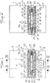
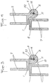
- la fig. 1 est une coupe axiale d'une charnière conforme à l'invention, selon un premier montage et dans une première configuration de fonctionnement;
- la fig. 2 est une coupe analogue à celle de la fig. 1 de la même charnière, mais dans une deuxième configuration de fonctionnement;
- la fig. 3 est une coupe suivant III-III de la fig. 1 ;
- la fig. 4 est une coupe suivant IV-IV de la fig. 1, et
- la fig. 5 est une coupe axiale d'une charnière conforme à l'invention, comprenant les éléments de la charnière de la fig. 1, mais assemblés selon un deuxième montage, distinct du premier.
- fig. 1 is an axial section of a hinge according to the invention, according to a first assembly and in a first operating configuration;
- fig. 2 is a section similar to that of FIG. 1 of the same hinge, but in a second operating configuration;
- fig. 3 is a section along III-III of FIG. 1;
- fig. 4 is a section on IV-IV of FIG. 1, and
- fig. 5 is an axial section of a hinge according to the invention, comprising the elements of the hinge of FIG. 1, but assembled according to a second assembly, distinct from the first.
La charnière représentée comprend:
- - un
premier corps 1, lui-même constituépar un étrier 2 à deux branches, adapté à recevoir un élément de panneau - porte vitrée ou autre -, etpar deux branches 3et 4 de réception d'un arbre de pivotement 5, - -
un deuxième corps 6, lui-même constituépar un étrier 7 à deux branches, permettant la fixation de la charnière sur la structure fixe supportant le panneau mobile, et par une pièce 8 de forme générale cylindrique.
- a
first body 1, itself constituted by astirrup 2 with two branches, adapted to receive a panel element - glass door or the like -, and by twobranches shaft 5, - - A
second body 6, itself constituted by abracket 7 with two branches, allowing the fixing of the hinge on the fixed structure supporting the movable panel, and by apart 8 of generally cylindrical shape.
La pièce cylindrique 8 est délimitée par deux faces transversales 9 et 10, perpendiculaires à l'axe géométrique 11 de l'arbre de pivotement 5, et est introduite entre les deux branches 3 et 4 du premier corps 1, les faces 9 et 10 de la pièce 8 étant disposées en regard des faces 12 et 13 desdites branches 3 et 4, respectivement, pratiquement sans jeu sauf celui nécessaire au montage et au fonctionnement.The
Les branches 3 et 4 du premier corps, et la pièce cylindrique 8 du deuxième corps, comportent des premiers alésages alignés en permanence 14, 15 et 16, respectivement, coaxiaux à l'axe géométrique, à l'intérieur desquels est logé l'arbre 5, monté coulissant par rapport au premier corps 1 et au deuxième corps 6, parallèlement à l'axe géométrique 11.The
Du côté opposé à leurs faces 12 et 13, les branches 3 et 4 sont munites de cavités cylindriques délimitées par un fond 17 et 18, ainsi que par une face cylindrique 19 et 20, et qui débouchent à l'extérieur desdites branches, respectivement.On the side opposite their
Dans la configuration de la fig. 1, le support 21 d'un doigt de blocage 22 est vissé en 23 sur l'extrémité de l'arbre 5 qui est disposée à gauche et est munie d'un filetage 24. Un contre-écrou 25, également vissé en 26 sur le filetage 24, bloque le support 21 par rapport à l'arbre 5 en toute position désirée, étant muni, pour ce faire, d'une rainure de vissage 27. Le support 21 et le contre-écrou 25 ont des diamètres sensiblement égaux entre eux, et peu inférieurs au diamètre commun des faces cylindriques 19 et 10, de sorte qu'ils sont susceptibles d'être contenus dans les cavités cylindriques correspondantes: dans la cavité de gauche (face cylindrique 19) dans la configuration de la fig. 1, et dans la cavité de droite (face cylindrique 20) dans la configuration de la fig. 5.In the configuration of fig. 1, the
Le doigt de blocage 22 est emmanché à force dans un trou 28 dont est muni le support 21, et dépasse de la face 29 de ce support qui est disposée en regard du fond 7 de la cavité cylindrique. L'axe géométrique 30 du doigt 22 est distinct de l'axe géométrique 11 de l'arbre 5, et en est écarté d'une distance D.The locking
Par ailleurs, on note que les branches 3 et 4 du premier corps, et la pièce cylindrique 8 du deuxième corps, sont munies de trous traversants 31, 32 et 33, respectivement, qui, dans la configuration de la fig. 1, sont alignés. En outre, l'extrémité du doigt de blocage 22, qui dépasse de la face 29 du support 21, est introduite à la fois dans l'orifice 31 de la branche 3, qu'il traverse, et dans l'orifice 33 de la pièce 8. La face 29 du support 21 est alors en appui sur le fond 17 de la cavité de gauche.Furthermore, it is noted that the
Dans la configuration de la fig. 2, on note que la face 29 du support 21 a pu être écartée du fond 17 de la cavité cylindrique d'une distance E qui est supérieure à la profondeur P d'introduction du doigt de blocage 22 dans l'orifice 33 dans la configuration précédente de la fig. 1. Le doigt de blocage 22 étant solidaire du support 21, il a lui-même été déplacé d'une distance E par rapport à sa position initiale et est, de ce fait, sorti hors de l'orifice 33. La distance E étant, par ailleurs, la distance maximale de recul du doigt de blocage 22, on constate en outre que celui-ci et, dans l'une et l'autre des deux configurations extrêmes décrites, introduit au moins partiellement (fig. 2) dans l'orifice de la branche 3 et est, de ce fait, solidarisé en permanence en rotation avec ladite branche 3, donc avec le premier corps 1 de la charnière.In the configuration of fig. 2, it is noted that the
Dans la cavité de la branche 4 du premier corps, délimitée par la face cylindrique 20 et le fond 18, est monté coulissant un poussoir 34 qui est emmanché à force sur l'extrémité 35 de l'arbre de pivotement 5 opposée au filetage 24. La face extérieure 36 du poussoir 34 constitue la face de poussée, alors que la face opposée 37 forme une butée de limitation de l'enfoncement du poussoir dans la cavité, et est en outre disposée en regard du fond 18 de cette cavité, en en étant écartée de la distance E dans la configuration de la fig. 1, et en étant au contraire au contact dudit fond 18 dans la configuration de la fig. 2. Le poussoir 34 comporte une face cylindrique interne 38 de diamètre inférieur à celui de la face 39 raccordée à la face de pousée 36, les faces 38 et 39 étant raccordées par un épaulement 40. Un ressort hélicoïdal 41 entoure la face cylindrique interne 38 du poussoir et est disposé entre le fond 18 de la cavité et l'épaulement 40, qu'il tend à écarter dudit fond 18.In the cavity of the
Les particularités suivantes doivent également être vues.The following peculiarities should also be seen.
Dans la configuration de la fig. 1, aucune poussée n'étant exercée sur la face de poussée 36 du poussoir 34, l'effet du ressort 41 est de mettre en appui la face 29 du support 21 du doigt de blocage sur le fond 17 de la cavité de gauche 19a (fig. 2). Le poussoir 34, encore partiellement introduit dans la cavité de droite 18a, fait cependant saillie d'une distance S par rapport à la face 1 a du corps 1 dans laquelle débouche la cavité 18a. La face 1 a est la face dite de commande de la poussée, et la distance S est évidemment réglable au moyen du vissage (23 et 24) de l'arbre 5 dans le support 21.In the configuration of fig. 1, no thrust being exerted on the thrust face 36 of the
Dans la configuration de la fig. 2, la poussée qui a été exercée sur la face 36 du poussoir 34 a provoqué l'introduction complète de celui-ci dans la cavité 18a, jusqu'à un retrait de sa face de poussée 36 d'une valeur R par rapport à la face 1 a.In the configuration of fig. 2, the thrust which has been exerted on the
Il doit encore être indiqué que le plan M perpendiculaire à l'axe géométrique 11, équidistant des faces 9 et 10 de la pièce 8, et distant de chacune d'elles d'une longueur L, constitue un plan de symétrie de cette pièce 8 et des branches 3 et 4 munies des cavités et des trous qui ont été définis. C'est pourquoi le montage de la fig. 1 dans lequel, d'une part, le support 21 et le contre-écrou 25 sont contenus dans la cavité de gauche à face cylindrique 19 et, d'autre part, le poussoir 34 est introduit dans la cavité de droite à face cylindrique 20 peut être, pour certaines applications, remplacé sans aucun usinage supplémentaire par le montage inverse, représentée sur la fig. 5, dans lequel, d'une part, le suport 21 et le contre-écrou 25 sont contenus dans la cavité de droite à face cylindrique 20 et, d'autre part, le poussoir 34 est introduit dans la cavité de gauche à face cylindrique 19. Le deuxième montage (fig. 5) est rigoureusement symétrique du premier (fig. 1 ) par rapport au plan M précité.It must also be indicated that the plane M perpendicular to the geometric axis 11, equidistant from the
Les diverses possibilités d'utilisation de la charnière décrite ci-avant vont maintenant être exposées.The various possibilities of using the hinge described above will now be explained.
Tout d'abord, on a réalisé un dispositif de blocage sélectif en position des deux corps d'une charnière.First of all, a selective locking device has been produced in position of the two bodies of a hinge.
Lorsque l'utilisateur n'agit aucunement sur le poussoir 34 (fig. 1), le ressort 41 agit seul et a pour effet:
- -
d'éloigner l'épaulement 40 dudit poussoir du fond 18 de la cavité de droite, - - de tirer l'arbre de pivotement 5 vers la droite, et
- - de pousser l'extrémité 42 du doigt de blocage 22 vers
la face 9 de la pièce 8, dans le cas où les trous 31et 33 ne seraient pas alignés, et, dans le cas contraire,d'introduire ce doigt 22 dans letrou 33.
- - move the
shoulder 40 away from said pusher from the bottom 18 of the right-hand cavity, - - pull the
pivot shaft 5 to the right, and - - push the
end 42 of the lockingfinger 22 towards theface 9 of thepart 8, in the case where theholes finger 22 into thehole 33.
Ainsi, avant l'introduction du doigt de blocage 22 dans l'orifice 33, les deux corps 1 et 2 pivotent librement autour de l'arbre 5 jusqu'à ce que le trou 33 soit disposé en regard de l'extrémité 42 du doigt de blocage 22. Alors, dans cette position, on constate l'introduction automatique de ce doigt de blocage 22 dans le trou 33. La branche 3 et la pièce 8 sont immobilisées l'une par rapport à l'autre par l'arbre 5 et le doigt de blocage 22 non coaxiaux.Thus, before the introduction of the locking
Naturellement, la pièce 8 peut comporter plusieurs trous 33 distincts, auxquels correspondent autant de positions distinctes de blocage des deux corps 1 et 6 de la charnière.Naturally, the
Peut également être disposé entre ces deux corps un dispositif de billes rappelées élastiquement vers des empreintes, ou un dispositif analogue connu, constituant un dispositif de maintien des deux corps en une ou plusieurs positions préférées, mais non bloquées, et susceptibles d'être abandonnées par simple poussée de commande du pivotement relatif des deux corps.Can also be arranged between these two bodies a device of balls resiliently biased towards imprints, or a known analogous device, constituting a device for holding the two bodies in one or more preferred positions, but not locked, and capable of being abandoned by simple push to control the relative pivoting of the two bodies.
Quand, à partir de la configuration de blocage en position des deux corps de la charnière représentée sur la fig. 1, l'utilisateur désire permettre de nouveau le pivotement relatif des deux corps de cette charnière, il lui suffit d'appuyer sur la face de poussée 36 du poussoir 34 pour, contrariant l'effet du ressort 41, faire coulisser ce poussoir 34, l'arbre 5, le support 21 et le doigt de blocage 22 qui en sont solidaires vers la gauche, et obtenir la configuration de la fig. 2 dans laquelle, le doigt de blocage 22 étant sorti du trou 33, le pivotement est redevenu libre.When, from the locking configuration in position of the two bodies of the hinge shown in FIG. 1, the user wishes to allow the relative pivoting of the two bodies of this hinge again, it suffices for him to press on the thrust face 36 of the
On aura noté la grande simplicité de la constitution des dispositions décrites, leur efficacité, ainsi que leurs possibilités de réglage. En effet, sur ce dernier point, l'assemblage du support 22 à l'arbre de pivotement 5 par vissage (23 et 24) rend possible le choix de la valeur de la distance E et, par conséquent, l'obtention même du blocage, compte tenu de la valeur de la profondeur maximale P d'introduction du doigt de blocage 22 dans le trou 33.We have noted the great simplicity of the constitution of the described arrangements, their effectiveness, as well as their adjustment possibilities. Indeed, on this last point, the assembly of the
La valeur de la distance E ayant été choisie, la mise en place du contre-écrou 25 en garantit l'invariabilité. La rainure 27 facilite le montage.The value of the distance E having been chosen, the positioning of the
L'interchangeabilité des montages des fig. 1 et 5 a déjà été mentionnée. Cette caractéristique est importante car, dans la configuration de la fig. 3, si le deuxième corps 6 est fixé sur la structure fixe (mur ou autre), le panneau mobile fixé sur le premier corps 1 ne peut pivoter qu'à l'intérieurd'un dièdre d'environ 180°. Dans certaines utilisations, un débattement dans le dièdre complémentaire à 360° est souhaité. Il est possible d'obtenir très facilement le montage correspondant avec la charnière proposée en adoptant son montage représenté sur la fig. 5, ce qui n'exige aucun usinage supplémentaire, aucune pièce supplémentaire. La symétrie des branches 3 et 4 et de la pièce 8 par rapport au plan M permet l'utilisation d'un seul élément pour deux applications distinctes qui, autrefois, nécessitaient le choix de deux charnières entièrement distinctes.The interchangeability of the assemblies of fig. 1 and 5 has already been mentioned. This characteristic is important because, in the configuration of FIG. 3, if the
Claims (9)
whereas at least one housing (33) is provided in the second body (6), that each housing (33) issues into the said face (9) of the second body (6) and is adapted to receive at least part of the locking pin (22) in a predetermined relative position of the first and second bodies (1 and 6), called locking position, that an elastic return member (41 ) is coupled between the locking pin (22) and one of the first (1) and second (6) bodies, and that a pressure applied on the free end (42) of the locking pin (22) towards the said face (9) of the second body (6) can cause the automatic introduction of said locking pin (22) in each housing (33), in the corresponding position locking the first and second bodies (1 and 6), and that the maximum spacing (E) controlled by the member (34) controlling the sliding movement of the locking pin (22) is at least equal to the depth (P) to which the locking pin (22) is sunk into each housing (33), thus allowing from a locking position the unlocking of the position of the first and second bodies (1 and 6),
characterized in that the locking finger (22) is axially made fast (21 to 28) with a pivoting shaft (5) already fast in rotation with the first body (1 ) and on which the second body (6) is pivotally mounted so that a thrust exerted via the control member (34) on said pivoting shaft (5) causes the release of the locking finger (22) from the housing (33) provided in the second body (6), thus ensuring the unlocking of the hinge and permitting the pivoting movement of the two bodies (1 and 6) one with respect to the other before reaching another locked position.
Applications Claiming Priority (2)
| Application Number | Priority Date | Filing Date | Title |
|---|---|---|---|
| FR7927156 | 1979-11-02 | ||
| FR7927156A FR2468712A1 (en) | 1979-11-02 | 1979-11-02 | SELECTIVE LOCKING HINGE |
Publications (2)
| Publication Number | Publication Date |
|---|---|
| EP0028544A1 EP0028544A1 (en) | 1981-05-13 |
| EP0028544B1 true EP0028544B1 (en) | 1983-07-20 |
Family
ID=9231275
Family Applications (1)
| Application Number | Title | Priority Date | Filing Date |
|---|---|---|---|
| EP19800401247 Expired EP0028544B1 (en) | 1979-11-02 | 1980-09-02 | Hinge lockable at will |
Country Status (3)
| Country | Link |
|---|---|
| EP (1) | EP0028544B1 (en) |
| DE (1) | DE3064282D1 (en) |
| FR (1) | FR2468712A1 (en) |
Families Citing this family (5)
| Publication number | Priority date | Publication date | Assignee | Title |
|---|---|---|---|---|
| DE3921492C2 (en) * | 1989-06-30 | 1995-09-21 | Melchert Beschlaege | Locking device |
| DE4024368A1 (en) * | 1990-08-01 | 1992-02-06 | Daimler Benz Ag | Door hinge for vehicle - has two halves and can be moved to 90 deg. locking and 180 deg. opening positions |
| DE4239359A1 (en) | 1992-11-24 | 1994-05-26 | Karl Loggen | Wrist band |
| EP1489251A1 (en) * | 2003-06-18 | 2004-12-22 | Tyrone Marine Hardware Co., Ltd. | Door and window blocking structure |
| FR2926838B1 (en) * | 2008-01-29 | 2012-08-17 | Jean Marc Veillerot | PAUMELLE HAVING ROLLING AUTOBLOCATION MEANS. |
Family Cites Families (3)
| Publication number | Priority date | Publication date | Assignee | Title |
|---|---|---|---|---|
| CH551560A (en) * | 1972-04-11 | 1974-07-15 | Kuemmerlin Walter | ARTICULATED FITTINGS FOR FOLDING LADDERS. |
| FR2392268A1 (en) * | 1976-12-06 | 1978-12-22 | Mullca | Automatically locking hinge for step ladder - has discs and ring containing pins sliding in holes under spring action |
| FR2399529A1 (en) * | 1977-08-04 | 1979-03-02 | Chatellerault Armes Cycles | ARTICULATION FOR FOLDING LADDERS |
-
1979
- 1979-11-02 FR FR7927156A patent/FR2468712A1/en active Granted
-
1980
- 1980-09-02 EP EP19800401247 patent/EP0028544B1/en not_active Expired
- 1980-09-02 DE DE8080401247T patent/DE3064282D1/en not_active Expired
Also Published As
| Publication number | Publication date |
|---|---|
| FR2468712B1 (en) | 1983-06-24 |
| FR2468712A1 (en) | 1981-05-08 |
| DE3064282D1 (en) | 1983-08-25 |
| EP0028544A1 (en) | 1981-05-13 |
Similar Documents
| Publication | Publication Date | Title |
|---|---|---|
| EP0265316B1 (en) | Locking system of a linear device for the rapid adjustment and blocking of a mobile part with respect to a fixed part | |
| EP1889992B1 (en) | Retractable key | |
| WO2011101562A1 (en) | Furniture caster or the like having locking means | |
| EP0028544B1 (en) | Hinge lockable at will | |
| EP0270425B1 (en) | Lock with a rotor connected to the bolt by a set of pinions | |
| EP1291479B1 (en) | Lock with universal mounting | |
| FR2808552A1 (en) | Lock with mechanical and electrical release, uses spring-loaded pin engaging in shallow recess in lock rotor to stop operation of lock and has a rotating cam under pin to allow it to move clear when correct key is detected | |
| CH629106A5 (en) | SECURITY FIXING FOR SKI. | |
| FR3042467A1 (en) | WHEEL ENGINE, TYPE TROTTINETTE | |
| EP1368693A1 (en) | Pair of spectacles with automatic bow opening mechanism | |
| FR2866045A1 (en) | Control knob for safety lock of e.g. protective barrier, has spring supported between core and casing through antifriction stop, and two locking units that are engaged to integrate casing and core for controlling opening of lock | |
| EP0906997A1 (en) | Locking device comprising a cam operated transmission element | |
| EP0894921B1 (en) | Closure device, specially mortise lock with a latch bolt, for a French window or similar | |
| EP2586940B1 (en) | Locking device of a wing | |
| EP1023513B1 (en) | Fail safe lock, in particular for elevating device landing door | |
| FR3096714A3 (en) | Comb type hinge for window and swing leaf doors | |
| EP0894928B1 (en) | Locking device, in particular a mortise lock for the wing of a door or a window | |
| EP0770745A1 (en) | Detachable handle for a door or a window especially in metallic frame | |
| EP0791708A2 (en) | Locking device, for a vehicle wing, with means for dead-locking of the actuating rods | |
| FR2699057A1 (en) | Adjustable device for locking the drawers of a piece of furniture and furniture equipped with such a device. | |
| EP0940529A1 (en) | Double plug security cylinder | |
| EP2253788A1 (en) | Device for blocking the rotation of a door and door comprising such a device | |
| EP2256275A1 (en) | Rotation blocking device of a door and door equipped with such device | |
| WO2024056478A1 (en) | Wheelchair wheel system | |
| EP0308354A1 (en) | Lock or espagnolette with a latch bolt |
Legal Events
| Date | Code | Title | Description |
|---|---|---|---|
| PUAI | Public reference made under article 153(3) epc to a published international application that has entered the european phase |
Free format text: ORIGINAL CODE: 0009012 |
|
| AK | Designated contracting states |
Designated state(s): AT BE CH DE FR GB IT LU NL SE |
|
| 17P | Request for examination filed |
Effective date: 19810609 |
|
| GRAA | (expected) grant |
Free format text: ORIGINAL CODE: 0009210 |
|
| AK | Designated contracting states |
Designated state(s): BE DE FR GB |
|
| REF | Corresponds to: |
Ref document number: 3064282 Country of ref document: DE Date of ref document: 19830825 |
|
| PLBE | No opposition filed within time limit |
Free format text: ORIGINAL CODE: 0009261 |
|
| STAA | Information on the status of an ep patent application or granted ep patent |
Free format text: STATUS: NO OPPOSITION FILED WITHIN TIME LIMIT |
|
| 26N | No opposition filed | ||
| PGFP | Annual fee paid to national office [announced via postgrant information from national office to epo] |
Ref country code: DE Payment date: 19840818 Year of fee payment: 5 |
|
| PGFP | Annual fee paid to national office [announced via postgrant information from national office to epo] |
Ref country code: FR Payment date: 19840928 Year of fee payment: 5 |
|
| PGFP | Annual fee paid to national office [announced via postgrant information from national office to epo] |
Ref country code: BE Payment date: 19840930 Year of fee payment: 5 |
|
| PG25 | Lapsed in a contracting state [announced via postgrant information from national office to epo] |
Ref country code: GB Effective date: 19880902 |
|
| PG25 | Lapsed in a contracting state [announced via postgrant information from national office to epo] |
Ref country code: BE Effective date: 19880930 |
|
| BERE | Be: lapsed |
Owner name: ADLER S.A. Effective date: 19880930 |
|
| PG25 | Lapsed in a contracting state [announced via postgrant information from national office to epo] |
Ref country code: FR Free format text: LAPSE BECAUSE OF NON-PAYMENT OF DUE FEES Effective date: 19890531 |
|
| GBPC | Gb: european patent ceased through non-payment of renewal fee | ||
| PG25 | Lapsed in a contracting state [announced via postgrant information from national office to epo] |
Ref country code: DE Effective date: 19890601 |
|
| REG | Reference to a national code |
Ref country code: FR Ref legal event code: ST |