EP0028408B2 - Hochtemperatur-Injektions- und Verdampfungssystem für die Gas-Chromatographie - Google Patents
Hochtemperatur-Injektions- und Verdampfungssystem für die Gas-Chromatographie Download PDFInfo
- Publication number
- EP0028408B2 EP0028408B2 EP80106711A EP80106711A EP0028408B2 EP 0028408 B2 EP0028408 B2 EP 0028408B2 EP 80106711 A EP80106711 A EP 80106711A EP 80106711 A EP80106711 A EP 80106711A EP 0028408 B2 EP0028408 B2 EP 0028408B2
- Authority
- EP
- European Patent Office
- Prior art keywords
- sample
- syringe
- vaporization zone
- plunger
- injection system
- Prior art date
- Legal status (The legal status is an assumption and is not a legal conclusion. Google has not performed a legal analysis and makes no representation as to the accuracy of the status listed.)
- Expired
Links
- 230000008016 vaporization Effects 0.000 title claims abstract description 59
- 238000009834 vaporization Methods 0.000 title claims abstract description 58
- 238000002347 injection Methods 0.000 title claims abstract description 40
- 239000007924 injection Substances 0.000 title claims abstract description 40
- 238000004817 gas chromatography Methods 0.000 title abstract description 4
- 239000012159 carrier gas Substances 0.000 claims abstract description 27
- 239000007789 gas Substances 0.000 claims description 13
- 239000012530 fluid Substances 0.000 claims description 11
- 238000012856 packing Methods 0.000 claims description 9
- 239000007787 solid Substances 0.000 claims description 9
- 238000004891 communication Methods 0.000 claims description 6
- 238000010438 heat treatment Methods 0.000 claims description 5
- 238000007789 sealing Methods 0.000 claims 3
- NBVXSUQYWXRMNV-UHFFFAOYSA-N fluoromethane Chemical compound FC NBVXSUQYWXRMNV-UHFFFAOYSA-N 0.000 claims 2
- 239000002184 metal Substances 0.000 claims 2
- 239000011347 resin Substances 0.000 claims 2
- 229920005989 resin Polymers 0.000 claims 2
- 239000002131 composite material Substances 0.000 claims 1
- -1 polytetrafluoroethylene Polymers 0.000 claims 1
- 229920001343 polytetrafluoroethylene Polymers 0.000 claims 1
- 239000004810 polytetrafluoroethylene Substances 0.000 claims 1
- 239000007788 liquid Substances 0.000 abstract description 40
- 239000004215 Carbon black (E152) Substances 0.000 abstract description 6
- 229930195733 hydrocarbon Natural products 0.000 abstract description 6
- 150000002430 hydrocarbons Chemical class 0.000 abstract description 6
- 238000009835 boiling Methods 0.000 abstract description 5
- 239000000523 sample Substances 0.000 description 117
- 239000000463 material Substances 0.000 description 12
- 238000006073 displacement reaction Methods 0.000 description 4
- 239000001307 helium Substances 0.000 description 4
- 229910052734 helium Inorganic materials 0.000 description 4
- SWQJXJOGLNCZEY-UHFFFAOYSA-N helium atom Chemical compound [He] SWQJXJOGLNCZEY-UHFFFAOYSA-N 0.000 description 4
- 238000000034 method Methods 0.000 description 3
- BQCADISMDOOEFD-UHFFFAOYSA-N Silver Chemical compound [Ag] BQCADISMDOOEFD-UHFFFAOYSA-N 0.000 description 2
- 230000000694 effects Effects 0.000 description 2
- 210000004907 gland Anatomy 0.000 description 2
- 238000009413 insulation Methods 0.000 description 2
- 238000005070 sampling Methods 0.000 description 2
- 239000004332 silver Substances 0.000 description 2
- 229910052709 silver Inorganic materials 0.000 description 2
- 229910001220 stainless steel Inorganic materials 0.000 description 2
- 239000010935 stainless steel Substances 0.000 description 2
- 239000006200 vaporizer Substances 0.000 description 2
- 101100293261 Mus musculus Naa15 gene Proteins 0.000 description 1
- 239000004809 Teflon Substances 0.000 description 1
- 229920006362 Teflon® Polymers 0.000 description 1
- 238000004458 analytical method Methods 0.000 description 1
- 230000004888 barrier function Effects 0.000 description 1
- 238000010276 construction Methods 0.000 description 1
- 238000001816 cooling Methods 0.000 description 1
- 238000000151 deposition Methods 0.000 description 1
- 230000000994 depressogenic effect Effects 0.000 description 1
- 238000009792 diffusion process Methods 0.000 description 1
- 230000009977 dual effect Effects 0.000 description 1
- 238000007689 inspection Methods 0.000 description 1
- 238000011835 investigation Methods 0.000 description 1
- 238000002955 isolation Methods 0.000 description 1
- 230000007774 longterm Effects 0.000 description 1
- 238000004519 manufacturing process Methods 0.000 description 1
- 239000000203 mixture Substances 0.000 description 1
- 239000012188 paraffin wax Substances 0.000 description 1
- 238000000926 separation method Methods 0.000 description 1
- 229920002379 silicone rubber Polymers 0.000 description 1
- 239000004945 silicone rubber Substances 0.000 description 1
Images

Classifications
-
- G—PHYSICS
- G01—MEASURING; TESTING
- G01N—INVESTIGATING OR ANALYSING MATERIALS BY DETERMINING THEIR CHEMICAL OR PHYSICAL PROPERTIES
- G01N30/00—Investigating or analysing materials by separation into components using adsorption, absorption or similar phenomena or using ion-exchange, e.g. chromatography or field flow fractionation
- G01N30/02—Column chromatography
- G01N30/04—Preparation or injection of sample to be analysed
- G01N30/06—Preparation
- G01N30/12—Preparation by evaporation
Definitions
- the invention relates to a gas chromatograph injection system for injecting a measured sample of fluid from a relatively low temperature sample stream into a relatively high temperature vaporization zone through which a carrier gas is flowing, comprising a sample block having inlet and outlet ports for the sample stream and a sample flow channel portion therebetween, a tubular closed end syringe member closed by a solid tip and having an aperture in the side thereof and a plunger having a tip portion and selectively movable toward and away from said closed end to receive fluid samples of a predetermined volume into said syringe, a pneumatic system arranged to move said syringe and withdrawn plunger from their original position together into said vaporization zone, to force said plunger toward said closed end to expel said measured sample into said vaporization zone, and to return said syringe and plunger to their original position, means to heat said vaporization zone, packing and guiding means in said sample block to guide the movement of said tubular syringe member on opposite sides of said sample flow channel and
- the hand syringe injection of a sample consists of first loading the syringe with a volume of sample by withdrawing the plunger. Next, the syringe needle is pushed through the septum, a small silicone rubber disc, of the injection port, and the plunger is depressed to discharge the sample by positive displacement into the injection port vaporization area. Finally, the syringe is withdrawn from the septum.
- the septum is the only barrier between the chromatographic process and the outside environment.
- the valve is generally heated and may be of the rotary, sliding plate or other types, consisting of a fixed volume sample loop or cavity through which liquid sample is generally flowing under pressure.
- the valve is indexed to the sample inject position the liquid volume trapped in the sample loop or cavity is vaporized. Vaporization takes place by flashing the material in the carrier gas port of the heated sample valve or built in heated vaporizer while the material is exposed to a flowing carrier gas stream.
- the hand syringe injection system besides not being continuous, suffers from loss of light material present in full boiling range samples.
- the syringe and sample have to be heated at atmospheric pressure to a point where the material is fluid enough to load and displace from the syringe. Liquid in the needle tip may be prematurely forced out by thermal expansion when the needle enters the hot septum, thus depositing some material onto the septum which may later gradually release and interfere with the current and/or later sample results. Both of these effects can be observed when comparing the results of sampling with closed and open systems.
- the septum must be changed daily because repeated puncturing will eventually destroy its mechanical strength which results in carrier gas leakage. If close attention is paid to the septum area upon withdrawal of the syringe, some vapors can be observed either exiting from the syringe needle or leaking momentarily from the septum, due to the pressure and high temperature required at the injection port to volatilize the liquid. This results in loss of material and varying sample volume.
- An attractive feature of a syringe is the positive displacement of the liquid into the vaporization . area, as compared to the heated sample valve.
- the sample valve relies on the sample loop or cavity to be at a sufficiently high enough temperature to flash volatilize the liquid so that it can be flushed out by the carrier gas. If the sample valve cannot be kept at a high enough temperature, some of the material, generally heavies, will remain in liquid form on the inner surface of the sample loop or cavity, thus preventing a correct analysis of the sample.
- liquid sample valve with its metered flow through sample loop or cavity under pressure is definitely better than the hand-held syringe.
- wider boiling range liquids require increased valve temperature to vaporize the liquid and increased pressure to maintain the light components as a liquid until time for injection. This prevents dual phase sampling which results in variable sample volumes.
- valves The temperature and pressure at which a sample valve can be maintained on a continuous basis is limited by the valve's materials of construction.
- Present state of the art valves have a maximum continuous operating temperature of about 204°C at which point the seals begin to deform and the valves begin to leak. This limits the liquid sample which can be successfully injected to those with end points below 399°C.
- Some manufacturers have valves they claim operate at about 349°C. But investigation indicates that the valves do not operate on a continuous basis or for very long.
- the DE-A 1 623086 discloses an injection and vaporization system for gas chromatography having a tubular syringe member having two apertures in the side thereof and a plunger selectively movable within a syringe needle to draw fluid samples from a fluid container into the syringe and to inject them into the vaporization zone.
- DE-A 2100089 discloses a system comprising a sample block having inlet and outlet ports for the sample stream and a sample flow channel portion therebetween, a tubular closed end syringe member having an aperture in the side thereof and a plunger selectively movable toward and away from said closed end to draw fluid samples of a predetermined volume into said syringe through said aperture, packing and guiding means in said sample block to guide the movement of said tubular syringe member on opposite sides of said sample flow channel and prevent leakage.
- a gas chromatograph injection system for injecting a measured sample of fluid from a relatively low temperature sample stream into a relatively high temperature vaporization zone through which a carrier gas is flowing, comprising a sample block having inlet and outlet ports for the sample stream and a sample flow channel portion therebetween, a tubular closed end syringe member closed by a solid tip and having an aperture in the side thereof and a plunger having a tip portion and selectively movable toward and away from said closed end to receive fluid samples of a predetermined volume into said syringe, a pneumatic system arranged to move said syringe and withdrawn plunger from their original position together into said vaporization zone, to force said plunger toward said closed end to expel said measured sample into said vaporization zone, and to return said syringe and plunger to their original position, means to heat said vaporization zone, packing and guiding means in said sample block to guide the movement of said tubular syringe member on opposite sides of said sample flow channel
- the invention basically involves the use of an automatic septumless injection syringe which:
- Said heating means heats said vaporization zone preferably to a temperature of at least 316°C, especially to a temperature of at least 329°C, while said sample block is insulated to remain at a temperature no greater than 204°C.
- the injection syringe is mounted in a pneumatic drive which consists of inner and outer pistons and cylinders into which compressed air is fed. Operation of air solenoid valves, preferably under the control of a microprocessor in a specific sequence, draws the liquid sample into the syringe, moves the syringe needle into the vaporization zone, displaces the liquid sample, and withdraws the syringe needle.
- the vaporization zone is attached in sealed relation to the sample block in axial alignment with the syringe and pneumatic drive.
- the sample block preferably consists of a stainless steel block which is cross bored to allow sample to flow through and across the syringe needle while a lateral opening in the syringe needle is moved in and out of the sample stream.
- the seal between the chromatographic process and the sample stream is made by means of a packing gland which is compressed against the outer wall of the syringe needle and a tapered cavity in the sample block.
- the injection sequence begins with compressed air slowly moving the inner position back, thus moving the syringe plunger back so as to load the syringe needle through the lateral opening with liquid sample under pressure.
- compressed air moves the outer piston, placing the lateral opening of the needle in the vaporization zone.
- the pressure is then applied to the opposite side of the inner piston so as to move the plunger forward and displace the liquid into the vaporization zone.
- the injection sequence ends when the pressure is applied to the opposite side of the outer piston which returns the lateral opening in the syringe needle to the reset position in the flowing liquid stream.
- the vaporization zone consists of an outer and inner section made from either stainless steel tubing or solid rod with a short piece of tubing extending from the top which penetrates the chromatographic column packing. The three pieces are fitted together and silver soldered or welded in place.
- the inner section is hollow with three spiral grooves cut in the outer wall of its main body portion while the end portions are smooth. The multiple grooves serve to ensure a more uniform flow to the injection zone.
- the outer section serves to mount the inner section and also as a heat sink and includes a side entrance for the carrier gas. The lower end of the outer section is screwed into the sample block and a pressure seal between the chromatographic process and the sample stream is produced by compressing a packing gland against the outer wall of the syringe needle and the inner wall of a cavity in the sample block.
- the carrier gas After the carrier gas enters the vaporization zone it is partially heated while spiraling down between the two sections. Exiting the spirals the flow continues uniformly down the outer surface of the annular area and then up the center, exiting the vaporization zone and onto the chromatographic column. At the time of sample injection the lateral opening of the syringe needle automatically moves up and well within the inner section of the vaporization zone. The liquid sample is then injected by positive displacement and flash vaporized. The sample vapors are entrained in the flowing carrier gas and subsequently move to the column to be chromatographed.
- the uniqueness of the invention comes from the fact that automatic septumless syringe injection and vaporization can be made with liquid hydrocarbon samples in the -42°C to 579°C boiling range from a closed system, such as a flowing liquid stream or high pressure sample bomb, with little or no loss of light material.
- the -42°C to 579°C sample can be homogeneously liquefied, it can be injected, vaporized and chromatographed. This has been verified by injection of normal paraffin blends of nC 4 through nC44.
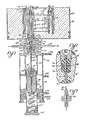
- the improved sample injection system is indicated generally at 10.
- the system is adapted to be used with a liquid sample stream 12 which is passed through a length of sample tubing 14 into a sample block 16.
- a small volume of sample is captured from the sample stream for injection into a carrier gas stream 18 in a manner to be hereinafter described.
- the carrier gas stream 18, typically helium is passed into a length of carrier gas tubing 20 which is directed, for the purpose of heating the gas, in a somewhat tortuous path into a vaporization zone 22 where the small captured sample from the sample stream 12 is injected into it.
- the vaporized sample is then directed through a tube 24 into a chromatographic column 26.
- the sample is separated into its various components in the usual manner within the column 26 and then exits the column through tubing 20' into a detector block 28 were the different components are sensed before the carrier gas exits the apparatus through tubing 20".
- Injection of the sample is accomplished by a syringe needle 32 which is hollow throughout its length except for a solid tip portion 32'.
- a plunger 34 is mounted within the hollow needle 32 and includes a tip portion 34' which normally fills the space behind the solid tip 32' but which can be drawn downwardly in the needle portion 32 away from the solid tip 32' in order to collect a measured volume of the sample stream 12. Movement of both the syringe needle 32 and the plunger 34 are accomplished by the piston and cylinder assembly indicated generally at 36.
- This assembly includes an outer needle control piston 38 and an inner plunger control piston 40. The pistons cooperate, respectively, with an outer cylinder portion 42 and an inner cylinder portion 44.
- Movement of the pistons within their respective cylinders is accomplished by causing air to enter one or more of the air tubes 48, 50, 52 and 54 in a desired sequence as will later be described in connection with Figs. 4-7.
- the syringe needle 32 is firmly engaged in a holder portion 58 which is shown on a larger scale in Fig. 3.
- the holder portion 58 is mounted in the upper end portion 59' of a vertically moving tube 59 which is shown as being integral with the needle control piston 38 but which could be formed separately and attached mechanically to the piston.
- the plunger 34 is anchored to the plunger control piston 40 by means of a set screw 62.
- the plunger control piston 40 is normally biased to the upper end of the cylinder 59 by a spring 64. When it is desired to withdraw the plunger 34, a charge of air is brought in through tube 48 and through axial openings 59" into communication with the top end of piston 40 which will be driven downwardly against the force of the spring 64.
- a sample is drawn into the syringe needle 32 through an aperture 66 which is formed in the side of the needle at the lower end of the needle tip 32'.
- the aperture 66 is in communication with the sample stream 12 present in the flow channel 68 within the block 16 so that withdrawal of the plunger 34 will draw a predetermined quantity of sample into the needle.
- the size of the sample is determined by the stroke length of the piston 40 and the inside diameter of the needle 32.
- a shoulder 67' on a replaceable end cap 67 contacts the lower end of plunger piston 40. To change the sample volume, one need merely replace the cap 67 with one having a longer or shorter shoulder extension 67 ' .
- a series of seals are provided to prevent leakage either to or from the piston and cylinder assembly 36 or to or from the vaporization zone 22.
- a pair of axially spaced lower seals 70, 72 are positioned between the flow channel 68 and the piston cylinder assembly 36 and a vent 74 is provided between the seals in a double block and bleed arrangement. In this arrangement, any leakage of the sample past seal 70 will be vented at 74 so that it cannot leak into the assembly 36 and likewise, any leakage from the assembly 36 past seal 72 will be vented before it can reach the sample stream.
- seals 76 and 78 which are preferably made of Teflon and a vent 80 between them.
- the latter structure is shown in more detail in Fig. 2.
- a spring means such as a pair of Belleville washers 82 are provided between the seals to continually apply an axial pressure to them.
- the vaporization zone 22 lies within an outer tube-like member 84, which has a necked-in lower tip portion 84' threaded into engagement with the sample block 16.
- an inner tube portion 86 Positioned inside the outer tube portion 84, and preferably silver soldered thereto is an inner tube portion 86 which has a three start spiral groove 86' around its exterior and in contact with the inner wall of the outer tube 84.
- a shoulder portion 84" separates the narrow end portion 84' from the main body portion 84 and forms a seat for an annular insulating ring 90.
- the necking down of the lower portion of the tube 84 significantly reduces the amount of heat which may be conducted from the normally hot upper end of the tube down to the sample block 16.
- Conductance of heat is further limited by means of the insulating ring 90 and by the cooling effect of the helium gas which expands by the fact that its pressure falls from about 2.4 atm to about 1.1 atm as it enters the vaporization zone. Additional isolation of the heat in the vaporization zone to prevent it from reaching the sample block 16 is achieved by the housing 98 which contains insulation 100. The insulation is positioned around and under the heater coils 102 so that the heat will be concentrated in the region of the detector block 28 and the tubes 84, 86 in which the carrier gas 18 is preheated before it is contacted by the injected sample in the vaporization zone 22.
- the detector block 28 which may be of the thermoconductivity diffusion type, for example, preferably contains a detector filament assembly 104 which is not shown in detail but which typically comprises a heated filament which is contacted by the carrier gas and is arranged along with a detector reference filament and two fixed resistors in a Wheatstone bridge circuit.
- the conductance of the gas contacted filament varies with changes in temperature but is constant when pure carrier gas is exiting the chromatographic column 26 through tubing 20', thus causing the bridge circuit to be in equilibrium.
- the discrete components of the hydrocarbon sample, which are separated in the column 26 contact the detector filament, sequential heating takes place as a result of thermoconductivity changes.
- the heater 102 must cause the inner tube 86 to reach a temperature of about 315°-343°C.
- helium is used as the carrier gas 18, such a temperature is sufficient to vaporize any liquid within the range which contacts the inner walls of the tube 86 since a C44 hydrocarbon which boils at atmospheric pressure in air at about 537°C will boil in the slightly pressurized helium in the vaporization zone 22 at a temperature of about 304°C.
- the temperature of the vaporization zone measured at Tv was 343°C the temperature of the interior of the sample block at T s was only 93°C.
- the seals 76, 78 are very well protected from being damaged by excessive temperatures.
- Figs. 4-7 are somewhat simplified representations which illustrate the positions of the various elements of the improved injection system of Fig. 1 during the injection cycle.
- the reference characters 110-186 are meant to refer to elements which correspond to the elements numbered 10-86 in Fig. 1.
- the carrier gas 118 passes in the direction of the arrow continually through the grooves 186' and up through the vaporization zone 122 toward the chromatographic column.
- the liquid 112 to be sampled passes continually through the sample block 116.
Landscapes
- Immunology (AREA)
- Pathology (AREA)
- Life Sciences & Earth Sciences (AREA)
- Chemical & Material Sciences (AREA)
- Analytical Chemistry (AREA)
- Biochemistry (AREA)
- General Health & Medical Sciences (AREA)
- General Physics & Mathematics (AREA)
- Health & Medical Sciences (AREA)
- Physics & Mathematics (AREA)
- Sampling And Sample Adjustment (AREA)
- Chemical Vapour Deposition (AREA)
- Medicines Containing Antibodies Or Antigens For Use As Internal Diagnostic Agents (AREA)
- Other Investigation Or Analysis Of Materials By Electrical Means (AREA)
- Vaporization, Distillation, Condensation, Sublimation, And Cold Traps (AREA)
- Medicines Containing Material From Animals Or Micro-Organisms (AREA)
- Steroid Compounds (AREA)
Claims (8)
Priority Applications (1)
| Application Number | Priority Date | Filing Date | Title |
|---|---|---|---|
| AT80106711T ATE6547T1 (de) | 1979-11-02 | 1980-10-31 | Hochtemperatur-injektions- und verdampfungssystem fuer die gas-chromatographie. |
Applications Claiming Priority (2)
| Application Number | Priority Date | Filing Date | Title |
|---|---|---|---|
| US06/090,818 US4289029A (en) | 1979-11-02 | 1979-11-02 | High temperature injection and vaporization system for gas chromatography |
| US90818 | 1998-06-04 |
Publications (3)
| Publication Number | Publication Date |
|---|---|
| EP0028408A1 EP0028408A1 (de) | 1981-05-13 |
| EP0028408B1 EP0028408B1 (de) | 1984-03-07 |
| EP0028408B2 true EP0028408B2 (de) | 1987-09-16 |
Family
ID=22224468
Family Applications (1)
| Application Number | Title | Priority Date | Filing Date |
|---|---|---|---|
| EP80106711A Expired EP0028408B2 (de) | 1979-11-02 | 1980-10-31 | Hochtemperatur-Injektions- und Verdampfungssystem für die Gas-Chromatographie |
Country Status (10)
| Country | Link |
|---|---|
| US (1) | US4289029A (de) |
| EP (1) | EP0028408B2 (de) |
| JP (1) | JPS5682447A (de) |
| AT (1) | ATE6547T1 (de) |
| CA (1) | CA1148764A (de) |
| DE (1) | DE3066866D1 (de) |
| ES (1) | ES496440A0 (de) |
| IN (1) | IN155008B (de) |
| PT (1) | PT72010B (de) |
| YU (1) | YU42363B (de) |
Families Citing this family (11)
| Publication number | Priority date | Publication date | Assignee | Title |
|---|---|---|---|---|
| DE2950744C2 (de) * | 1979-12-17 | 1982-02-18 | Tibor 3000 Hannover Bernath | Vorrichtung zum Entnehmen einer heißen Gasprobe aus einer Kammer und zum Zuführen der Probe zu einem Analysenmeßgerät |
| US4458541A (en) * | 1981-10-13 | 1984-07-10 | Beckman Instruments, Inc. | Liquid sample injection valve for gas chromatographs |
| DE3435216A1 (de) * | 1984-09-26 | 1986-04-03 | Studiengesellschaft Kohle mbH, 4330 Mülheim | Verfahren und vorrichtung zur split- und splitlosen probenaufgabe mit der spritze auf kapillarsaeulen |
| FR2580808B1 (fr) * | 1985-04-19 | 1987-06-26 | Armines | Dispositif automatique de micro-echantillonnage et d'injection de fluides sous pression |
| FR2652897B1 (fr) * | 1989-10-10 | 1994-01-07 | Institut Francais Petrole | Dispositif et procede pour transferer un echantillon de fluide entre deux chambres et application notamment a la chromatographie gazeuse. |
| US5750906A (en) * | 1995-11-02 | 1998-05-12 | Chiron Diagnostics Corporation | Multifunction valve |
| JP3003565B2 (ja) * | 1995-11-27 | 2000-01-31 | 株式会社島津製作所 | ガスクロマトグラフへの試料注入方法 |
| FR2765338B1 (fr) * | 1997-06-25 | 1999-07-23 | Inst Francais Du Petrole | Dispositif de prelevement et/ou d'injection d'un echantillon de fluide permettant de conserver l'equilibre chimique et/ou thermodynamique |
| US6257076B1 (en) * | 1999-01-26 | 2001-07-10 | Merlin Instrument Company | Sample injector with plunger release for chemical analysis systems |
| CN100552451C (zh) * | 2006-06-02 | 2009-10-21 | 中国石油兰州石油化工公司 | 一种低沸点烃类中微量含氧化合物的测定方法及设备 |
| US10508976B1 (en) * | 2017-03-31 | 2019-12-17 | Advanced Micro Instruments, Inc. | Gas sampling device and method |
Family Cites Families (8)
| Publication number | Priority date | Publication date | Assignee | Title |
|---|---|---|---|---|
| US3137174A (en) * | 1962-11-09 | 1964-06-16 | Le Roy R Hawk | Fluid metering device |
| US3306502A (en) * | 1965-04-28 | 1967-02-28 | Prec Sampling Corp | Apparatus for injection of fluids |
| US3482450A (en) * | 1967-12-01 | 1969-12-09 | Precision Sampling Corp | Sample inlet systems for analytical instruments |
| US3508442A (en) * | 1968-09-18 | 1970-04-28 | Hewlett Packard Co | Automatic liquid sampler for chromatography |
| NL7000303A (de) * | 1969-01-20 | 1970-07-22 | ||
| DE2100089C3 (de) * | 1971-01-02 | 1973-09-27 | Siemens Ag, 1000 Berlin U. 8000 Muenchen | Gaschromatographische Injektionsvorrichtung |
| SU412546A1 (de) * | 1971-02-22 | 1974-01-25 | ||
| DE2620756C3 (de) * | 1976-05-11 | 1979-03-22 | Siemens Ag, 1000 Berlin Und 8000 Muenchen | Probeninjektionsvorrichtung für die Prozeß-Gaschromatographie mit Kapillarsäulen und Betriebsverfahren für eine solche Vorrichtung |
-
1979
- 1979-11-02 US US06/090,818 patent/US4289029A/en not_active Expired - Lifetime
-
1980
- 1980-10-31 CA CA000363693A patent/CA1148764A/en not_active Expired
- 1980-10-31 DE DE8080106711T patent/DE3066866D1/de not_active Expired
- 1980-10-31 EP EP80106711A patent/EP0028408B2/de not_active Expired
- 1980-10-31 PT PT72010A patent/PT72010B/pt not_active IP Right Cessation
- 1980-10-31 IN IN786/DEL/80A patent/IN155008B/en unknown
- 1980-10-31 ES ES496440A patent/ES496440A0/es active Granted
- 1980-10-31 AT AT80106711T patent/ATE6547T1/de not_active IP Right Cessation
- 1980-10-31 YU YU2799/80A patent/YU42363B/xx unknown
- 1980-11-01 JP JP15454780A patent/JPS5682447A/ja active Granted
Also Published As
| Publication number | Publication date |
|---|---|
| IN155008B (de) | 1984-12-22 |
| EP0028408B1 (de) | 1984-03-07 |
| DE3066866D1 (en) | 1984-04-12 |
| JPS5682447A (en) | 1981-07-06 |
| EP0028408A1 (de) | 1981-05-13 |
| ATE6547T1 (de) | 1984-03-15 |
| JPH0130105B2 (de) | 1989-06-16 |
| PT72010B (en) | 1981-12-17 |
| YU279980A (en) | 1983-02-28 |
| CA1148764A (en) | 1983-06-28 |
| YU42363B (en) | 1988-08-31 |
| ES8201030A1 (es) | 1981-12-01 |
| PT72010A (en) | 1980-11-01 |
| ES496440A0 (es) | 1981-12-01 |
| US4289029A (en) | 1981-09-15 |
Similar Documents
| Publication | Publication Date | Title |
|---|---|---|
| EP0028408B2 (de) | Hochtemperatur-Injektions- und Verdampfungssystem für die Gas-Chromatographie | |
| US3604267A (en) | Sample injection apparatus | |
| Mol et al. | Large volume sample introduction using temperature programmable injectors: implications of liner diameter | |
| US4422860A (en) | On-column capillary gas chromatographic injector | |
| EP0525950B1 (de) | Thermisches Modulationseinlasssystem für Gaschromatographie | |
| US5032151A (en) | System and method for automated cool on-column injection with column diameters less than 530 μm | |
| US4732046A (en) | Method and apparatus for the introduction of a vaporizable sample into an analytical test apparatus | |
| US4300393A (en) | Sample introduction apparatus for gas chromatographic analysis using packed or capillary bore open tubular columns and method of testing | |
| US4766760A (en) | Method of chromatographic analysis of a mixture of liquid substances and a gas chromatograph for carrying out the method | |
| US5338514A (en) | Vented capillary gas chromatography apparatus | |
| US4559063A (en) | Multi purpose on column injection | |
| US3366149A (en) | Injection system for gas chromatography | |
| JP2759238B2 (ja) | ガス・クロマトグラフィー装置 | |
| US5009591A (en) | Pyrolyzer for gas chromatography | |
| US3592046A (en) | Precolumn inlet for chromatographs | |
| US4476732A (en) | Septumless jet stream on-column injector for chromatography | |
| US4004881A (en) | Apparatus for generating carrier gas-test specimen vapor mixtures for delivery into a gas chromatograph | |
| US4440550A (en) | On-column injector | |
| Grob et al. | Splitless injection of up to hundreds of microliters of liquid samples in capillary GC: Part II, experimental results | |
| EP0699303B1 (de) | Verfahren und vorrichtung für die gaschromatographische analyse grossvolumiger proben | |
| US4474588A (en) | Unheated septumless on-column injection system for capillary gas chromatography | |
| EP2341337B1 (de) | Verbessertes Kapselinjektionssystem für Gaschromatografie | |
| US3592064A (en) | Method for transferring a sample to be analyzed into the column of a gas chromatograph, and system for carrying out the method | |
| US6451614B1 (en) | Method and device for the vaporization injection | |
| US3355950A (en) | Chromatographic sample injection apparatus |
Legal Events
| Date | Code | Title | Description |
|---|---|---|---|
| PUAI | Public reference made under article 153(3) epc to a published international application that has entered the european phase |
Free format text: ORIGINAL CODE: 0009012 |
|
| AK | Designated contracting states |
Designated state(s): AT BE CH DE FR GB IT NL SE |
|
| 17P | Request for examination filed |
Effective date: 19810415 |
|
| ITF | It: translation for a ep patent filed | ||
| GRAA | (expected) grant |
Free format text: ORIGINAL CODE: 0009210 |
|
| AK | Designated contracting states |
Designated state(s): AT BE CH DE FR GB IT LI NL SE |
|
| REF | Corresponds to: |
Ref document number: 6547 Country of ref document: AT Date of ref document: 19840315 Kind code of ref document: T |
|
| REF | Corresponds to: |
Ref document number: 3066866 Country of ref document: DE Date of ref document: 19840412 |
|
| ET | Fr: translation filed | ||
| PLBI | Opposition filed |
Free format text: ORIGINAL CODE: 0009260 |
|
| 26 | Opposition filed |
Opponent name: SIEMENS AKTIENGESELLSCHAFT, BERLIN UND MUENCHEN Effective date: 19841207 |
|
| NLR1 | Nl: opposition has been filed with the epo |
Opponent name: SIEMENS AKTIENGESELLSCHAFT |
|
| RHK2 | Main classification (correction) |
Ipc: G01N 30/18 |
|
| NLXE | Nl: other communications concerning ep-patents (part 3 heading xe) |
Free format text: IPC CHANGED TO G01N 30/18 |
|
| PUAH | Patent maintained in amended form |
Free format text: ORIGINAL CODE: 0009272 |
|
| STAA | Information on the status of an ep patent application or granted ep patent |
Free format text: STATUS: PATENT MAINTAINED AS AMENDED |
|
| 27A | Patent maintained in amended form |
Effective date: 19870916 |
|
| AK | Designated contracting states |
Kind code of ref document: B2 Designated state(s): AT BE CH DE FR GB IT LI NL SE |
|
| ET3 | Fr: translation filed ** decision concerning opposition | ||
| NLR2 | Nl: decision of opposition | ||
| NLR3 | Nl: receipt of modified translations in the netherlands language after an opposition procedure | ||
| ITTA | It: last paid annual fee | ||
| PGFP | Annual fee paid to national office [announced via postgrant information from national office to epo] |
Ref country code: AT Payment date: 19921014 Year of fee payment: 13 |
|
| PGFP | Annual fee paid to national office [announced via postgrant information from national office to epo] |
Ref country code: CH Payment date: 19921026 Year of fee payment: 13 |
|
| PG25 | Lapsed in a contracting state [announced via postgrant information from national office to epo] |
Ref country code: LI Effective date: 19931031 Ref country code: CH Effective date: 19931031 Ref country code: AT Effective date: 19931031 |
|
| REG | Reference to a national code |
Ref country code: CH Ref legal event code: PL |
|
| EAL | Se: european patent in force in sweden |
Ref document number: 80106711.7 |
|
| PGFP | Annual fee paid to national office [announced via postgrant information from national office to epo] |
Ref country code: FR Payment date: 19951010 Year of fee payment: 16 |
|
| PGFP | Annual fee paid to national office [announced via postgrant information from national office to epo] |
Ref country code: SE Payment date: 19951017 Year of fee payment: 16 |
|
| PGFP | Annual fee paid to national office [announced via postgrant information from national office to epo] |
Ref country code: GB Payment date: 19951023 Year of fee payment: 16 |
|
| PGFP | Annual fee paid to national office [announced via postgrant information from national office to epo] |
Ref country code: NL Payment date: 19951024 Year of fee payment: 16 |
|
| PGFP | Annual fee paid to national office [announced via postgrant information from national office to epo] |
Ref country code: DE Payment date: 19951026 Year of fee payment: 16 |
|
| PGFP | Annual fee paid to national office [announced via postgrant information from national office to epo] |
Ref country code: BE Payment date: 19951213 Year of fee payment: 16 |
|
| PG25 | Lapsed in a contracting state [announced via postgrant information from national office to epo] |
Ref country code: GB Effective date: 19961031 Ref country code: BE Effective date: 19961031 |
|
| PG25 | Lapsed in a contracting state [announced via postgrant information from national office to epo] |
Ref country code: SE Effective date: 19961101 |
|
| BERE | Be: lapsed |
Owner name: UOP INC. Effective date: 19961031 |
|
| PG25 | Lapsed in a contracting state [announced via postgrant information from national office to epo] |
Ref country code: NL Effective date: 19970501 |
|
| GBPC | Gb: european patent ceased through non-payment of renewal fee |
Effective date: 19961031 |
|
| PG25 | Lapsed in a contracting state [announced via postgrant information from national office to epo] |
Ref country code: FR Effective date: 19970630 |
|
| NLV4 | Nl: lapsed or anulled due to non-payment of the annual fee |
Effective date: 19970501 |
|
| PG25 | Lapsed in a contracting state [announced via postgrant information from national office to epo] |
Ref country code: DE Effective date: 19970701 |
|
| EUG | Se: european patent has lapsed |
Ref document number: 80106711.7 |
|
| REG | Reference to a national code |
Ref country code: FR Ref legal event code: ST |