EP0028183B1 - Dispositif de rétention pour carter de compresseur d'une turbomachine - Google Patents
Dispositif de rétention pour carter de compresseur d'une turbomachine Download PDFInfo
- Publication number
- EP0028183B1 EP0028183B1 EP80401471A EP80401471A EP0028183B1 EP 0028183 B1 EP0028183 B1 EP 0028183B1 EP 80401471 A EP80401471 A EP 80401471A EP 80401471 A EP80401471 A EP 80401471A EP 0028183 B1 EP0028183 B1 EP 0028183B1
- Authority
- EP
- European Patent Office
- Prior art keywords
- rings
- coaxial
- compressor
- annular member
- blades
- Prior art date
- Legal status (The legal status is an assumption and is not a legal conclusion. Google has not performed a legal analysis and makes no representation as to the accuracy of the status listed.)
- Expired
Links
- 239000000463 material Substances 0.000 claims description 18
- 229910052751 metal Inorganic materials 0.000 claims description 4
- 239000002184 metal Substances 0.000 claims description 4
- 239000002657 fibrous material Substances 0.000 claims description 3
- 238000004804 winding Methods 0.000 claims description 3
- FGUJWQZQKHUJMW-UHFFFAOYSA-N [AlH3].[B] Chemical compound [AlH3].[B] FGUJWQZQKHUJMW-UHFFFAOYSA-N 0.000 claims description 2
- 239000002131 composite material Substances 0.000 claims description 2
- 229920005989 resin Polymers 0.000 claims description 2
- 239000011347 resin Substances 0.000 claims description 2
- 239000011343 solid material Substances 0.000 claims description 2
- 229920003002 synthetic resin Polymers 0.000 claims description 2
- 239000000057 synthetic resin Substances 0.000 claims description 2
- 239000000853 adhesive Substances 0.000 claims 1
- 230000001070 adhesive effect Effects 0.000 claims 1
- 238000004073 vulcanization Methods 0.000 claims 1
- 239000012634 fragment Substances 0.000 description 14
- 230000014759 maintenance of location Effects 0.000 description 6
- 229910000831 Steel Inorganic materials 0.000 description 3
- 238000006073 displacement reaction Methods 0.000 description 3
- 239000010959 steel Substances 0.000 description 3
- RTAQQCXQSZGOHL-UHFFFAOYSA-N Titanium Chemical compound [Ti] RTAQQCXQSZGOHL-UHFFFAOYSA-N 0.000 description 2
- 238000004519 manufacturing process Methods 0.000 description 2
- 239000010936 titanium Substances 0.000 description 2
- 229910052719 titanium Inorganic materials 0.000 description 2
- 229920000049 Carbon (fiber) Polymers 0.000 description 1
- 239000004642 Polyimide Substances 0.000 description 1
- 238000010521 absorption reaction Methods 0.000 description 1
- 229910052782 aluminium Inorganic materials 0.000 description 1
- XAGFODPZIPBFFR-UHFFFAOYSA-N aluminium Chemical compound [Al] XAGFODPZIPBFFR-UHFFFAOYSA-N 0.000 description 1
- 239000004917 carbon fiber Substances 0.000 description 1
- 229910003460 diamond Inorganic materials 0.000 description 1
- 239000010432 diamond Substances 0.000 description 1
- 230000000694 effects Effects 0.000 description 1
- 239000000835 fiber Substances 0.000 description 1
- 239000003365 glass fiber Substances 0.000 description 1
- 229920001721 polyimide Polymers 0.000 description 1
- 230000000750 progressive effect Effects 0.000 description 1
Images
Classifications
-
- F—MECHANICAL ENGINEERING; LIGHTING; HEATING; WEAPONS; BLASTING
- F01—MACHINES OR ENGINES IN GENERAL; ENGINE PLANTS IN GENERAL; STEAM ENGINES
- F01D—NON-POSITIVE DISPLACEMENT MACHINES OR ENGINES, e.g. STEAM TURBINES
- F01D21/00—Shutting-down of machines or engines, e.g. in emergency; Regulating, controlling, or safety means not otherwise provided for
- F01D21/04—Shutting-down of machines or engines, e.g. in emergency; Regulating, controlling, or safety means not otherwise provided for responsive to undesired position of rotor relative to stator or to breaking-off of a part of the rotor, e.g. indicating such position
- F01D21/045—Shutting-down of machines or engines, e.g. in emergency; Regulating, controlling, or safety means not otherwise provided for responsive to undesired position of rotor relative to stator or to breaking-off of a part of the rotor, e.g. indicating such position special arrangements in stators or in rotors dealing with breaking-off of part of rotor
-
- F—MECHANICAL ENGINEERING; LIGHTING; HEATING; WEAPONS; BLASTING
- F05—INDEXING SCHEMES RELATING TO ENGINES OR PUMPS IN VARIOUS SUBCLASSES OF CLASSES F01-F04
- F05D—INDEXING SCHEME FOR ASPECTS RELATING TO NON-POSITIVE-DISPLACEMENT MACHINES OR ENGINES, GAS-TURBINES OR JET-PROPULSION PLANTS
- F05D2220/00—Application
- F05D2220/30—Application in turbines
- F05D2220/32—Application in turbines in gas turbines
- F05D2220/327—Application in turbines in gas turbines to drive shrouded, high solidity propeller
-
- Y—GENERAL TAGGING OF NEW TECHNOLOGICAL DEVELOPMENTS; GENERAL TAGGING OF CROSS-SECTIONAL TECHNOLOGIES SPANNING OVER SEVERAL SECTIONS OF THE IPC; TECHNICAL SUBJECTS COVERED BY FORMER USPC CROSS-REFERENCE ART COLLECTIONS [XRACs] AND DIGESTS
- Y02—TECHNOLOGIES OR APPLICATIONS FOR MITIGATION OR ADAPTATION AGAINST CLIMATE CHANGE
- Y02T—CLIMATE CHANGE MITIGATION TECHNOLOGIES RELATED TO TRANSPORTATION
- Y02T50/00—Aeronautics or air transport
- Y02T50/60—Efficient propulsion technologies, e.g. for aircraft
Definitions
- the invention relates to a retention device for the compressor casing of a double-flow turbomachine consisting of a metal ferrule coaxial with the axis of the compressor and surrounding the rotor, bearing on its internal face opposite the blade ends a material capable of coming into wear contact with the end of the blades, the shell being externally lined with a coaxial annular structure.
- the retention of blade fragments likely to escape from the turbomachine rotors rotating at high speed required the development of devices allowing the evacuation of the blade or the fragment without it causing damage to the rest of blading.
- the known devices are intended either to retain the fragments from the rupture, or to fragment them so that they can be removed without damage.
- U.S. Patent 3,241,813 describes a device for retaining turbine rotor fragments.
- a ring formed in a resistant material surrounds the rotor and maintains an annular body made of a metal capable of withstanding the impact of the fragments without risk of rupture.
- the annular body has, opposite the rotor blades, an annular channel.
- Part of the kinetic energy of the blade fragment or of the ejected blade is dissipated, on impact, by deformation or rupture of the ring and the rest of the energy, by friction of the ring and of the annular body in the housing of the housing where they are held by tightening.
- the annular channel is lined internally with a softer material than that of the annular body so as to allow the fragments to penetrate there by losing their energy and to be maintained there.
- the material chosen is aluminum.
- the devices described are effective but have the disadvantage of being of a fairly significant weight. Indeed, the materials used for the ring and the annular body are generally high-strength steels of relatively large thickness. It follows a significant increase in the weight of the aircraft. Replacing steel with titanium, which has a lower specific mass, reduces mass but increases manufacturing costs.
- French Patent No. 1,604,806 describes projectile-resistant structures made up of layers of fibrous material and layers formed of parts made of rigid material with a diamond hardness index exceeding 700. These rigid parts are rods or tubes with thick wall, logs, gravel or natural pebbles. The density of the plates thus obtained is of the order of 2.5. The rigid parts have the function not only to resist the action of a projectile, but also to deflect it and cause it to break into fragments.
- the object of the invention is to produce a device, the structure of which consists of a particular assembly of material, at least part of which is of low density.
- the retention device is characterized in that the coaxial annular structure consists of a stack of elements of revolution coaxial with the axis of the compressor, said elements being composed at least in part of circular rings produced in two types of solid materials stacked alternately in the longitudinal direction of the turbo-machine, the dimension of said rings in the longitudinal direction being small compared to their dimension in the radial direction.
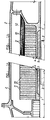
- FIGS 1A and 1B show an embodiment of the invention.
- the retention device for the compressor casing of a double-flow turbomachine consists of a metal ferrule 1, preferably made of steel or titanium, fixed inside the compressor casing 2. Opposite the compressor vanes 3 , a recess 4 in the shell 1 receives a material 5 capable of coming into wear contact with the end of the blades and acting as a seal.
- the ferrule 1 On its external diameter, the ferrule 1 is lined with a coaxial annular structure consisting of a stack of elements of revolution coaxial with the axis of the compressor.
- the elements of revolution consist of circular rings 10 and 11 coaxial with the axis of the compressor stacked one on the other on the external lateral surface of the shell 1.
- These rings are produced in two types of materials stacked alternately.
- the rings 10 are formed from a flexible and deformable material of the fibrous material type, glass or carbon fibers for example, linked by a polymerizable resin and the rings 11 from a less deformable material of the metallic, bimetallic or type composite with high characteristics, for example boron-aluminum.
- the choice of different materials is made in each case so as to combine the interesting properties of the associated materials.
- the rings are glued or vulcanized with each other.
- Figure 1B further shows a coil 12, outside the rings, consisting for example of a polyimide fiber, whether or not embedded in a synthetic resin, which holds the assembly.
- a coil 12 outside the rings, consisting for example of a polyimide fiber, whether or not embedded in a synthetic resin, which holds the assembly.
Landscapes
- Engineering & Computer Science (AREA)
- Mechanical Engineering (AREA)
- General Engineering & Computer Science (AREA)
- Structures Of Non-Positive Displacement Pumps (AREA)
Description
- L'invention concerne un dispositif de rétention pour carter de compresseur d'une turbomachine à double flux constitué d'une virole métallique coaxiale à l'axe du compresseur et entourant le rotor, portant sur sa face interne en regard des extrémités d'aubes un matériau susceptible d'entrer en contact d'usure avec l'extrémité des aubes, la virole étant doublée extérieurement d'une structure annulaire coaxiale.
- La rétention des fragments d'aubes susceptibles de s'échapper des rotors de turbomachine tournant à grande vitesse a nécessité la mise au point de dispositifs permettant l'évacuation de l'aube ou du fragment sans que celui-ci cause des avaries au restant de l'aubage. Les dispositifs connus ont pour but soit de retenir les fragments provenant de la rupture, soit de les fragmenter afin qu'ils puissent être évacués sans dommage.
- Le brevet des Etats-Unis d'Amérique n° 3 241 813 décrit un dispositif de rétention de fragments de rotor de turbine. Un anneau formé dans un matériau résistant entoure le rotor et maintient un corps annulaire constitué d'un métal susceptible de résister à l'impact des fragments sans risque de rupture. Le corps annulaire présente, face aux aubes du rotor, un canal annulaire.
- Une partie de l'énergie cinétique du fragment d'aube ou de l'aube éjectée est dissipée, lors de l'impact, par déformation ou rupture de l'anneau et le reste de l'énergie, par frottement de l'anneau et du corps annulaire dans le logement du carter où ils sont maintenus par serrage.
- Dans une deuxième forme de réalisation décrite, le canal annulaire est garni intérieurement d'un matériau plus mou que celui du corps annulaire de manière à permettre aux fragments d'y pénétrer en perdant leur énergie et d'y être maintenus. Le matériau choisi est de l'aluminium.
- Les dispositifs décrits sont efficaces mais présentent l'inconvénient d'être d'un poids assez important. En effet, les matériaux employés pour l'anneau et le corps annulaire sont généralement des aciers à haute résistance d'une épaisseur relativement importante. Il s'ensuit une augmentation de la masse de l'avion non négligeable. Le remplacement de l'acier par le titane, de masse spécifique plus faible, réduit la masse mais augmente les coûts de fabrication.
- Le brevet français n° 1 604 806 décrit des structures résistant aux projectiles constituées de couches de matière fibreuse et de couches formées de pièces en matière rigide d'un indice de dureté au diamant dépassant 700. Ces pièces rigides sont des tiges ou des tubes à paroi épaisse, des billes, des graviers ou cailloux naturels. La densité des plaques ainsi obtenue est de l'ordre de 2,5. Les pièces rigides ont pour fonction non seulement de résister à l'action d'un projectile, mais également de le faire dévier et de provoquer sa rupture en fragments.
- La réalisation de structure de rétention pour carter de compresseur basée sur les enseignements de ce dernier brevet n'est pas aisée à mettre en oeuvre par suite de l'emploi de matériau rigide de très grande dureté. L'assemblage de ces éléments de blindage ne permet pas d'obtenir des couches cylindriques facilitant le déplacement du fragment d'aube ou de l'aube dans le matériau et l'absorption progressive de son énergie cinétique.
- L'invention a pour but la réalisation d'un dispositif dont la structure est constituée d'un assemblage particulier de matériau dont au moins une partie est de faible densité.
- Le dispositif de rétention selon l'invention, est caractérisé en ce que la structure annulaire coaxiale est constituée d'un empilement d'éléments de révolution coaxiaux à l'axe du compresseur, lesdits éléments étant composés au moins en partie d'anneaux circulaires réalisés en deux types de matériaux solides empilés alternativement dans le sens longitudinal de la turbo- machine, la dimension desdits anneaux dans le sens longitudinal étant faible par rapport à leur dimension dans le sens radial.
- Les explications et figures données ci-après à titre d'exemple permettront de comprendre comment l'invention peut être réalisée.
- Les figures 1A et 1B montrent une forme de réalisation de l'invention.
- Le dispositif de rétention pour carter de compresseur d'une turbomachine à double flux est constitué d'une virole métallique 1, de préférence en acier ou en titane, fixée à l'intérieur du carter de compresseur 2. En face des aubes 3 de compresseur, un évidement 4 de la virole 1 reçoit un matériau 5 susceptible de rentrer en contact d'usure avec l'extrémité des aubes et faisant office de joint d'étanchéité.
- Sur son diamètre externe, la virole 1 est doublée d'une structure annulaire coaxiale constituée d'un empilement d'éléments de révolution coaxiaux à l'axe du compresseur.
- Comme représenté aux figures 1A et 1B, les éléments de révolution sont constitués d'anneaux circulaires 10 et 11 coaxiaux à l'axe du compresseur empilés les uns sur les autres sur la surface latérale extérieure de la virole 1. Ces anneaux sont réalisés en deux types de matériaux empilés alternativement. Par exemple les anneaux 10 sont formés d'un matériau souple et déformable du type matériau fibreux, fibres de verre ou de carbone par exemple, lié par une résine polymérisable et les anneaux 11 par un matériau moins déformable du type métallique, bimétallique ou de type composite à hautes caractéristiques, par exemple bore-aluminium. Le choix des matériaux différents est fait dans chaque cas de manière à conjuguer les propriétés intéressantes des matériaux associés. Les anneaux sont collés ou vulcanisés les uns avec les autres.
- La figure 1 B montre en outre un bobinage 12, extérieur aux anneaux, constitué par exemple d'une fibre polyimide, noyée ou non dans une résine synthétique, qui maintient l'ensemble. En cas d'éjection d'aube ou de fragment de partie rotative du compresseur, l'impact du fragment sur le dispositif selon l'invention provoque une déformation de l'empilement se déforme à la manière d'un accordéon ou encore, vu en coupe, à la manière d'un éventail. L'énergie cinétique du fragment est ainsi partiellement absorbée par ce travail d'ouverture entre couches et par les frottements entre anneaux qui l'accompagnent. De plus, l'impact provoque une somme de déplacements élémentaires vers l'extérieur qui absorbent également l'énergie. Ces déplacements qui aboutissent à une expansion du dispositif également dans le sens radial sont rendus possibles grâce à l'espace ménagé entre le diamètre externe des anneaux 10 et 11 et le carter 2. Dans le cas où un bobinage 12 est adjoint, les anneaux 10 et 11 procurent une résistance à la perforation des fragments et absorbent l'énergie par leur mode particulier de déformations et le bobinage 12 procure un effet supplémentaire de rétention obtenu par répartition circonférentielle des efforts et des déplacements.
Claims (6)
Applications Claiming Priority (2)
| Application Number | Priority Date | Filing Date | Title |
|---|---|---|---|
| FR7926580 | 1979-10-23 | ||
| FR7926580A FR2467978A1 (fr) | 1979-10-23 | 1979-10-23 | Dispositif de retention pour carter de compresseur d'une turbomachine |
Publications (2)
| Publication Number | Publication Date |
|---|---|
| EP0028183A1 EP0028183A1 (fr) | 1981-05-06 |
| EP0028183B1 true EP0028183B1 (fr) | 1983-06-01 |
Family
ID=9231063
Family Applications (1)
| Application Number | Title | Priority Date | Filing Date |
|---|---|---|---|
| EP80401471A Expired EP0028183B1 (fr) | 1979-10-23 | 1980-10-16 | Dispositif de rétention pour carter de compresseur d'une turbomachine |
Country Status (4)
| Country | Link |
|---|---|
| US (1) | US4411589A (fr) |
| EP (1) | EP0028183B1 (fr) |
| DE (1) | DE3063625D1 (fr) |
| FR (1) | FR2467978A1 (fr) |
Families Citing this family (43)
| Publication number | Priority date | Publication date | Assignee | Title |
|---|---|---|---|---|
| GB2095749B (en) * | 1981-03-25 | 1984-12-12 | Rolls Royce | Gas turbine engine having improved resistance for foreign object ingestion damage |
| US4598449A (en) * | 1981-12-21 | 1986-07-08 | United Technologies Corporation | Beam for a containment structure |
| US4718818A (en) * | 1981-12-21 | 1988-01-12 | United Technologies Corporation | Containment structure |
| US4534698A (en) * | 1983-04-25 | 1985-08-13 | General Electric Company | Blade containment structure |
| FR2547357A1 (fr) * | 1983-06-09 | 1984-12-14 | Snecma | Structure de retention pour carter de turbomachine |
| DE3401742C2 (de) * | 1984-01-19 | 1986-08-14 | MTU Motoren- und Turbinen-Union München GmbH, 8000 München | Rotor für einen Axialverdichter |
| GB2159886B (en) * | 1984-06-07 | 1988-01-27 | Rolls Royce | Fan duct casing |
| US4639188A (en) * | 1984-12-04 | 1987-01-27 | Sundstrand Corporation | Turbine wheel containment |
| FR2574476B1 (fr) * | 1984-12-06 | 1987-01-02 | Snecma | Carter de retention pour soufflante de turboreacteur |
| DE3529979A1 (de) * | 1985-08-22 | 1987-03-05 | Mtu Muenchen Gmbh | Einrichtung zur verhinderung der ausbreitung von titanfeuer bei turbomaschinen, insbesondere gasturbinen- bzw. gasturbinenstrahltriebwerken |
| DE3862989D1 (de) * | 1987-04-15 | 1991-07-04 | Mtu Muenchen Gmbh | Berstschutzring fuer turbotriebwerksgehaeuse. |
| US4955192A (en) * | 1988-12-12 | 1990-09-11 | Sundstrand Corporation | Containment ring for radial inflow turbine |
| US5188505A (en) * | 1991-10-07 | 1993-02-23 | General Electric Company | Structural ring mechanism for containment housing of turbofan |
| US5447411A (en) * | 1993-06-10 | 1995-09-05 | Martin Marietta Corporation | Light weight fan blade containment system |
| GB2281941B (en) * | 1993-09-15 | 1996-05-08 | Rolls Royce Plc | Containment structure |
| GB2288639B (en) * | 1994-04-20 | 1998-10-21 | Rolls Royce Plc | Ducted fan gas turbine engine nacelle assembly |
| FR2728619B1 (fr) * | 1994-12-21 | 1997-01-24 | Hispano Suiza Sa | Bouclier de protection d'une turbomachine |
| DE19640654A1 (de) * | 1996-10-02 | 1998-04-09 | Asea Brown Boveri | Berstschutzvorrichtung für Radialturbinen von Turboladern |
| US6059523A (en) * | 1998-04-20 | 2000-05-09 | Pratt & Whitney Canada Inc. | Containment system for containing blade burst |
| US6290455B1 (en) * | 1999-12-03 | 2001-09-18 | General Electric Company | Contoured hardwall containment |
| DE10259943A1 (de) * | 2002-12-20 | 2004-07-01 | Rolls-Royce Deutschland Ltd & Co Kg | Schutzring für das Fan-Schutzgehäuse eines Gasturbinentriebswerks |
| US20060093847A1 (en) * | 2004-11-02 | 2006-05-04 | United Technologies Corporation | Composite sandwich with improved ballistic toughness |
| US7246990B2 (en) * | 2004-12-23 | 2007-07-24 | General Electric Company | Composite fan containment case for turbine engines |
| GB0510538D0 (en) | 2005-05-24 | 2005-06-29 | Rolls Royce Plc | A rotor blade containment assembly for a gas turbine engine |
| GB0510540D0 (en) * | 2005-05-24 | 2005-06-29 | Rolls Royce Plc | Containment casing |
| US8403624B2 (en) * | 2007-12-12 | 2013-03-26 | General Electric Company | Composite containment casings having an integral fragment catcher |
| US8371009B2 (en) * | 2007-12-12 | 2013-02-12 | General Electric Company | Methods for repairing composite containment casings |
| US8046915B2 (en) * | 2007-12-12 | 2011-11-01 | General Electric Company | Methods for making composite containment casings |
| GB2459646B (en) * | 2008-04-28 | 2011-03-30 | Rolls Royce Plc | A fan assembly |
| US8858156B2 (en) * | 2010-08-12 | 2014-10-14 | General Electric Company | Fragment containment assembly and method for adding a fragment containment assembly to a turbine |
| GB201103682D0 (en) * | 2011-03-04 | 2011-04-20 | Rolls Royce Plc | A turbomachine casing assembly |
| EP2620653B1 (fr) * | 2012-01-25 | 2015-06-24 | Rolls-Royce plc | Ensemble carter de turbomachine avec cavité de rétention d'aubes |
| GB201217055D0 (en) * | 2012-09-25 | 2012-11-07 | Rolls Royce Plc | An engine casing assembly |
| FR3004215B1 (fr) * | 2013-04-05 | 2018-04-20 | Airbus Operations | Ecran de protection pour carter de turbomachine |
| DE102013207452A1 (de) * | 2013-04-24 | 2014-11-13 | MTU Aero Engines AG | Gehäuseabschnitt einer Turbomaschinenverdichter- oder Turbomaschinenturbinenstufe |
| US10167727B2 (en) * | 2014-08-13 | 2019-01-01 | United Technologies Corporation | Gas turbine engine blade containment system |
| US9714583B2 (en) * | 2014-08-21 | 2017-07-25 | Honeywell International Inc. | Fan containment cases for fan casings in gas turbine engines, fan blade containment systems, and methods for producing the same |
| GB201417416D0 (en) * | 2014-10-02 | 2014-11-19 | Rolls Royce Plc | Fan track liner assembly |
| US11002294B2 (en) * | 2016-10-07 | 2021-05-11 | General Electric Comany | Impact force dispersal assembly for turbine engines and methods of fabricating the same |
| US10487684B2 (en) | 2017-03-31 | 2019-11-26 | The Boeing Company | Gas turbine engine fan blade containment systems |
| US10550718B2 (en) | 2017-03-31 | 2020-02-04 | The Boeing Company | Gas turbine engine fan blade containment systems |
| US20200011203A1 (en) * | 2018-07-06 | 2020-01-09 | General Electric Company | Blade containment structure |
| US11065825B2 (en) * | 2018-12-05 | 2021-07-20 | Raytheon Technologies Corporation | High temperature composite seal |
Family Cites Families (13)
| Publication number | Priority date | Publication date | Assignee | Title |
|---|---|---|---|---|
| GB868197A (en) * | 1956-09-28 | 1961-05-17 | Rolls Royce | Improvements in or relating to protective arrangements for use with rotating parts |
| US3203180A (en) * | 1960-03-16 | 1965-08-31 | Nathan C Price | Turbo-jet powerplant |
| GB1085329A (fr) * | 1964-01-21 | |||
| FR1421189A (fr) * | 1964-01-21 | 1965-12-10 | Garrett Corp | Dispositif de protection contre l'éclatement des rotors de turbines |
| US3261228A (en) * | 1964-04-02 | 1966-07-19 | United Aircraft Corp | Disk fragment energy absorption and containment means |
| US3298248A (en) * | 1964-11-02 | 1967-01-17 | United Aircraft Corp | Torsional impact limiter |
| GB1245415A (en) * | 1968-09-13 | 1971-09-08 | Rolls Royce | Improvements in or relating to fluid flow machines |
| US3556675A (en) * | 1969-01-29 | 1971-01-19 | Gen Electric | Turbomachinery rotor with integral shroud |
| US3602602A (en) * | 1969-05-19 | 1971-08-31 | Avco Corp | Burst containment means |
| GB1485032A (en) * | 1974-08-23 | 1977-09-08 | Rolls Royce | Gas turbine engine casing |
| GB1466385A (en) * | 1974-11-21 | 1977-03-09 | Rolls Royce | Containment shields for gas turbine engines |
| GB1547610A (en) * | 1975-05-09 | 1979-06-20 | Skega Ab | Wear liners for abrasive-material handling equipment |
| FR2406074A1 (fr) * | 1977-10-11 | 1979-05-11 | Snecma | Dispositif de securite pour machine tournante axiale |
-
1979
- 1979-10-23 FR FR7926580A patent/FR2467978A1/fr active Granted
-
1980
- 1980-10-16 EP EP80401471A patent/EP0028183B1/fr not_active Expired
- 1980-10-16 DE DE8080401471T patent/DE3063625D1/de not_active Expired
- 1980-10-21 US US06/199,192 patent/US4411589A/en not_active Expired - Lifetime
Also Published As
| Publication number | Publication date |
|---|---|
| DE3063625D1 (en) | 1983-07-07 |
| FR2467978A1 (fr) | 1981-04-30 |
| US4411589A (en) | 1983-10-25 |
| EP0028183A1 (fr) | 1981-05-06 |
| FR2467978B1 (fr) | 1984-09-07 |
Similar Documents
| Publication | Publication Date | Title |
|---|---|---|
| EP0028183A1 (fr) | Dispositif de rétention pour carter de compresseur d'une turbomachine | |
| EP0027756B1 (fr) | Dispositif de sécurité en cas de rupture d'élément rotatif de turbomachine | |
| EP0128819B1 (fr) | Structure de rétention pour carter de turbomachine | |
| CA2871481C (fr) | Renfort structurel metallique d'aube en composite de turbomachine | |
| EP1406019B1 (fr) | Rotor à tambour pour une turbomachine | |
| CA2628626C (fr) | Aube de soufflante | |
| EP0374003B1 (fr) | Turbomachine comportant un dispositif de freinage entre rotor de turbine et carter d'échappement | |
| FR2565629A1 (fr) | Enveloppe amelioree de conduit de soufflante | |
| EP3578760B2 (fr) | Aube de soufflante en matériau composite avec grand jeu intégré | |
| EP2872746B1 (fr) | Procédé de fabrication d'un carter de turbomachine dans un matériau composite et carter associé | |
| FR2491545A1 (fr) | Bandage pour le serrage radial des segments d'une roue a ailettes segmentee pour turbines | |
| EP2886804B1 (fr) | Dispositif d'étanchéité pour un compresseur de turbomachine | |
| EP0030179B1 (fr) | Structure de rétention pour carter de compresseur d'une turbomachine | |
| CA2373100C (fr) | Racleur optimise pour conduite | |
| WO2016151233A1 (fr) | Ensemble d'anneau de turbine comprenant une pluralite de secteurs d'anneau en materiau composite a matrice ceramique | |
| EP4172470A1 (fr) | Carter pour une turbomachine d'aeronef et procede de fabrication de carter | |
| CA2500986C (fr) | Systeme de blocage d'un arbre principal de moteur a palier fusible | |
| JPS61140638A (ja) | はずみ車エネルギ保存装置 | |
| WO1992012376A1 (fr) | Raidisseur a structure renforcee | |
| FR3121951A1 (fr) | Systeme de renforcement pour un carter de soufflante en materiau composite, carter de soufflante et turbomachine correspondants | |
| EP1593817A1 (fr) | Turbomachine dotée d'un système de protection d'arbre principal de moteur à palier fusible | |
| EP3918204A1 (fr) | Carter de soufflante pour une turbomachine d'aeronef | |
| FR3004215A1 (fr) | Ecran de protection pour carter de turbomachine | |
| FR3135109A1 (fr) | Anneau pour turbine de turbomachine | |
| EP0362074B1 (fr) | Roue de turbine grande vitesse en matériau composite |
Legal Events
| Date | Code | Title | Description |
|---|---|---|---|
| PUAI | Public reference made under article 153(3) epc to a published international application that has entered the european phase |
Free format text: ORIGINAL CODE: 0009012 |
|
| 17P | Request for examination filed |
Effective date: 19801022 |
|
| AK | Designated contracting states |
Designated state(s): DE FR GB |
|
| GRAA | (expected) grant |
Free format text: ORIGINAL CODE: 0009210 |
|
| AK | Designated contracting states |
Designated state(s): DE FR GB |
|
| REF | Corresponds to: |
Ref document number: 3063625 Country of ref document: DE Date of ref document: 19830707 |
|
| PLBE | No opposition filed within time limit |
Free format text: ORIGINAL CODE: 0009261 |
|
| STAA | Information on the status of an ep patent application or granted ep patent |
Free format text: STATUS: NO OPPOSITION FILED WITHIN TIME LIMIT |
|
| 26N | No opposition filed | ||
| PGFP | Annual fee paid to national office [announced via postgrant information from national office to epo] |
Ref country code: FR Payment date: 19920924 Year of fee payment: 13 |
|
| PGFP | Annual fee paid to national office [announced via postgrant information from national office to epo] |
Ref country code: GB Payment date: 19921007 Year of fee payment: 13 |
|
| PGFP | Annual fee paid to national office [announced via postgrant information from national office to epo] |
Ref country code: DE Payment date: 19921230 Year of fee payment: 13 |
|
| PG25 | Lapsed in a contracting state [announced via postgrant information from national office to epo] |
Ref country code: GB Effective date: 19931016 |
|
| GBPC | Gb: european patent ceased through non-payment of renewal fee |
Effective date: 19931016 |
|
| PG25 | Lapsed in a contracting state [announced via postgrant information from national office to epo] |
Ref country code: FR Effective date: 19940630 |
|
| PG25 | Lapsed in a contracting state [announced via postgrant information from national office to epo] |
Ref country code: DE Effective date: 19940701 |
|
| REG | Reference to a national code |
Ref country code: FR Ref legal event code: ST |