EP0028102A2 - Gasbrenner - Google Patents
Gasbrenner Download PDFInfo
- Publication number
- EP0028102A2 EP0028102A2 EP80303653A EP80303653A EP0028102A2 EP 0028102 A2 EP0028102 A2 EP 0028102A2 EP 80303653 A EP80303653 A EP 80303653A EP 80303653 A EP80303653 A EP 80303653A EP 0028102 A2 EP0028102 A2 EP 0028102A2
- Authority
- EP
- European Patent Office
- Prior art keywords
- blade member
- blade
- blank
- openings
- lip
- Prior art date
- Legal status (The legal status is an assumption and is not a legal conclusion. Google has not performed a legal analysis and makes no representation as to the accuracy of the status listed.)
- Granted
Links
Images


Classifications
-
- F—MECHANICAL ENGINEERING; LIGHTING; HEATING; WEAPONS; BLASTING
- F23—COMBUSTION APPARATUS; COMBUSTION PROCESSES
- F23D—BURNERS
- F23D14/00—Burners for combustion of a gas, e.g. of a gas stored under pressure as a liquid
- F23D14/02—Premix gas burners, i.e. in which gaseous fuel is mixed with combustion air upstream of the combustion zone
- F23D14/04—Premix gas burners, i.e. in which gaseous fuel is mixed with combustion air upstream of the combustion zone induction type, e.g. Bunsen burner
- F23D14/045—Premix gas burners, i.e. in which gaseous fuel is mixed with combustion air upstream of the combustion zone induction type, e.g. Bunsen burner with a plurality of burner bars assembled together, e.g. in a grid-like arrangement
Definitions
- the invention relates to a gas burner of the bladed type, for use particularly in domestic gasfired appliances, to the blade members of the burner, and to the method of manufacture of the blade members.
- the individual blades are mounted in a parallel, closely spaced relation on a common mixing chamber such that internal cavities of the blades communicate with the chamber. Gaseous fuel is passed into the chamber and entrains primary air therewith, the fuel and air being mixed in the chamber and passing through these blades to outlet apertures where the mixture is ignited, secondary air being available at the outlet apertures.
- Each blade is secured to the mixing chamber for example by welding.
- a blade member for use in a gas burner, the blade member having an internal cavity defined by a pair of side walls, each side wall having an opening therein coaxial with an opening in the other side wall to provide a passage through the blade member which is in communication with the internal cavity, the openings having outwardly extending lips of different dimensions, the side walls having one connecting edge portion formed with an outlet aperture arrangement, and the internal cavity being closed along the other connecting edge portions of the side walls.
- the blade member is formed of stainless steel.
- said other connecting edge portions of the side walls are clinched together.
- said other connecting edge portion may be spot welded.
- the present invention also provides a gas burner comprising a plurality of blade members according to any of the preceding claims, the blade members being connected together by the lip of each blade member having the smaller dimension being fitted within the other of the lips of an adjacent blade member, such that the blade members are retained substantially parallel to one another with said one connecting edge portions facing in the same direction, an end one of the plurality of the blade members being provided with means for closing the outwardly facing opening thereof, and the other end one of the blade members having means for mounting a gas inlet adjacent to the outwardly facing opening thereof.
- the present invention further provides a method of manufacturing a blade member for use in a gas burner, the method comprising pressing a blank out of a sheet of material, forming an outlet aperture arrangement over a longitudinally extending area of the blank, forming a pair of openings one on either side of said area, and forming each opening with a projecting lip, the lips being of different dimensions, the pressing of the blank being such that the edges are displaced relative to the remaining part of the blank in a direction opposite to that in which the lips extend, the blade member being formed by folding along each side of said area such that the openings are coaxial and the edges engage together and are sealed.
- the displaced edge to one side of the central area has a width greater than the other, such that the edges can be clinched together for sealing.
- the edges can be sealed for example by spot welding.
- a blank 10 for a blade member 11 intended to be used in a gas burner is pressed from a sheet of material such as low grade stainless steel., and is of substantially diamond configuration, this being a suitable shape for pressing a plurality of blanks from the sheet with minimum wastage of material.
- the area of the blank 10 inwardly of the edges thereof is embossed relative to the edges to define relatively displaced peripheral areas 12, 14 for a purpose hereinafter described.
- the peripheral areas are separated by a section 18 which is embossed together with the remaining area of the blank.
- This arrangement comprises a plurality of cross shaped flame ports or apertures 20 and smaller flame retention holes or ports 22 provided around each of the apertures 20, although it should be appreciated that the ports 20 may be of other shapes.
- the blank 10 is further provided with a pair of extruded openings 24, 26 whose axes lie on a transverse centre line 28 of the blank and are equispaced to either side of the central area having the outlet aperture arrangement.
- Each of the openings 24, 26 is formed with an annular lip 30, 32 respectively projecting from the blank in the direction of embossing.
- the lip 30 has a smaller diameter than the lip 32 and an inwardly turned free edge for a purpose hereinafter described.
- the blank is folded along each side of the central area defined by the outlet aperture arrangement, such that the openings 24, 26 are coaxial with one another and the peripheral areas 12, 14 abut and are secured together in a sealing manner, for example, by spot welding.
- wails 34, 36 defined between the peripheral areas 12, 14 respectively and the sections 18 are folded inwardly relative to one another on to the inner faces of the sections 18 and abut one another for spot welding.
- the embossing of the main area of the blank thus defines in the final form of the blade member an internal cavity defined by side walls 38, 40 which provides communication between the openings 24, 26 and the outlet apertures 22.
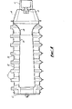
- a plurality of the formed blade members 11 are connected together as shown in Fig. 4.
- the blade members 11 are arranged parallel to one another with their larger diameter lips 32 on corresponding sides such that, to connect one blade member to another, the smaller diameter l ip 30 of one blade member is fitted within the larger diameter lip 32 of the adjacent member.
- the inwardly turned edge facilitates the lead in.
- the dimensions of the lips 30, 32 are such that a tight fit is provided and no further connections are necessary for sealing because of the low pressure of the gas being used and also the fact that the burner apparatus is located within a surrounding chamber.
- the outwardly extending l ip of the blade member at one end receives an end cap 42 to close the opening, and the blade member at the other end is arranged to mount a gas inlet pipe, on a connection 44 having an injector 45, by means of a bracket 46 in a conventional manner, such that primary air is entrained when the gas passes from the inlet in to the adjacent opening of the end blade member.
- a venturi arrangement comprising ports 48, 50 is provided in the opening adjacent to the gas inlet for even distribution of the gas and air mixture to ⁇ 11 the blade members 11.
- the burner so formed thus has a chamber for mixing of the gas and air defined by the co-operating lips of the openings and no separate mixing chamber is required.
- the burner is therefore considerably easier and cheaper to make than the conventional burner where individual blade members have to be fixed to a common mixing chamber by welding or the like.
- the burner formed by the blade members 11 arranged in a parallel closely spaced relation provides good gas distribution and a good flame, additional apertures assisting in holding down the flame as necessary. It will be appreciated that a burner having any desired number of blade members 11 is easily produced and also in the event of damage to a blade member it will be possible to dismantle the burner and replace the damaged blade member.
- peripheral areas 12, 14 may be formed of different widths such that the peripheral area of greater width can be clinched over the other area as an alternative to brazing or the like.
- the advantage of this is that the blade member can be manufactured to its finished form in the one workshop.
Landscapes
- Engineering & Computer Science (AREA)
- Chemical & Material Sciences (AREA)
- Combustion & Propulsion (AREA)
- Mechanical Engineering (AREA)
- General Engineering & Computer Science (AREA)
- Gas Burners (AREA)
Applications Claiming Priority (2)
| Application Number | Priority Date | Filing Date | Title |
|---|---|---|---|
| GB7936503 | 1979-10-20 | ||
| GB7936503 | 1979-10-20 |
Publications (3)
| Publication Number | Publication Date |
|---|---|
| EP0028102A2 true EP0028102A2 (de) | 1981-05-06 |
| EP0028102A3 EP0028102A3 (en) | 1981-07-15 |
| EP0028102B1 EP0028102B1 (de) | 1984-05-23 |
Family
ID=10508676
Family Applications (1)
| Application Number | Title | Priority Date | Filing Date |
|---|---|---|---|
| EP19800303653 Expired EP0028102B1 (de) | 1979-10-20 | 1980-10-16 | Gasbrenner |
Country Status (2)
| Country | Link |
|---|---|
| EP (1) | EP0028102B1 (de) |
| DE (1) | DE3067959D1 (de) |
Cited By (1)
| Publication number | Priority date | Publication date | Assignee | Title |
|---|---|---|---|---|
| TWI621813B (zh) * | 2016-09-26 | 2018-04-21 | Grand Mate Co Ltd | burner |
Citations (4)
| Publication number | Priority date | Publication date | Assignee | Title |
|---|---|---|---|---|
| US2840151A (en) * | 1955-09-06 | 1958-06-24 | Comb Enginerring Inc | Gas burner of multi section port construction |
| US3412940A (en) * | 1966-06-13 | 1968-11-26 | Luciano Ferroli Tredicesimo | Burner for town gas, liquefied gas, natural gas and mixtures thereof, and adapted to be fitted on boilers, stoves, air heaters and the like |
| GB1231890A (de) * | 1967-10-17 | 1971-05-12 | ||
| DE2257382A1 (de) * | 1972-11-23 | 1974-06-06 | Silvio Polidoro | Gasbrenner |
-
1980
- 1980-10-16 DE DE8080303653T patent/DE3067959D1/de not_active Expired
- 1980-10-16 EP EP19800303653 patent/EP0028102B1/de not_active Expired
Patent Citations (4)
| Publication number | Priority date | Publication date | Assignee | Title |
|---|---|---|---|---|
| US2840151A (en) * | 1955-09-06 | 1958-06-24 | Comb Enginerring Inc | Gas burner of multi section port construction |
| US3412940A (en) * | 1966-06-13 | 1968-11-26 | Luciano Ferroli Tredicesimo | Burner for town gas, liquefied gas, natural gas and mixtures thereof, and adapted to be fitted on boilers, stoves, air heaters and the like |
| GB1231890A (de) * | 1967-10-17 | 1971-05-12 | ||
| DE2257382A1 (de) * | 1972-11-23 | 1974-06-06 | Silvio Polidoro | Gasbrenner |
Cited By (2)
| Publication number | Priority date | Publication date | Assignee | Title |
|---|---|---|---|---|
| TWI621813B (zh) * | 2016-09-26 | 2018-04-21 | Grand Mate Co Ltd | burner |
| US10352557B2 (en) | 2016-09-26 | 2019-07-16 | Grand Mate Co., Ltd. | Burner for gas apparatus |
Also Published As
| Publication number | Publication date |
|---|---|
| EP0028102B1 (de) | 1984-05-23 |
| EP0028102A3 (en) | 1981-07-15 |
| DE3067959D1 (en) | 1984-06-28 |
Similar Documents
| Publication | Publication Date | Title |
|---|---|---|
| RU2319071C2 (ru) | Горелка печи, духовки или гриля, а также способ изготовления упомянутой горелки | |
| EP2256408B1 (de) | Ofen- oder grillbrenner | |
| US3386431A (en) | Burner construction and method and apparatus for making the same and the like | |
| AU640742B2 (en) | Jet burner construction, heating apparatus utilizing the jet burner construction, and methods of making the same | |
| EP0267671A1 (de) | Gasbrenner für Gasfeuer | |
| US6939126B2 (en) | Gas burner | |
| WO1993012379A1 (en) | Jet burner construction, heating apparatus utilizing the jet burner consturction and methods of making the same | |
| US3718426A (en) | Burner | |
| US5873713A (en) | Fuel/air supply assembly for gas burners | |
| EP0657691A1 (de) | Misch- und Diffusionselement für einen atmosphärischen Brenner | |
| US5176512A (en) | Inshot burner cluster apparatus | |
| US3837789A (en) | Gas burner | |
| US2701610A (en) | Cluster gas burner | |
| US5052920A (en) | Gas burner and method | |
| US6916174B2 (en) | Gas burner | |
| EP0028102B1 (de) | Gasbrenner | |
| US5445519A (en) | Jet burner construction heating apparatus utilizing the jet burner construction and methods of making the same | |
| US5433602A (en) | Jet burner construction, heating apparatus utilizing the jet burner construction, and methods of making the same | |
| US3694133A (en) | Fuel burner crossover arrangement | |
| GB2063453A (en) | Gas Burners | |
| HU186931B (en) | Atmospheric mixed gas burner advantageously for gas-fired household appliances | |
| US5372498A (en) | Jet burner construction heating apparatus utilizing the jet burner construction and methods of making the same | |
| EP0283901B1 (de) | Gas-Flächenbrenner für Heizungskessel | |
| DE3415946C2 (de) | ||
| KR970046925A (ko) | 예비혼합 버너 |
Legal Events
| Date | Code | Title | Description |
|---|---|---|---|
| PUAI | Public reference made under article 153(3) epc to a published international application that has entered the european phase |
Free format text: ORIGINAL CODE: 0009012 |
|
| AK | Designated contracting states |
Designated state(s): BE DE FR IT NL |
|
| PUAL | Search report despatched |
Free format text: ORIGINAL CODE: 0009013 |
|
| AK | Designated contracting states |
Designated state(s): BE DE FR IT NL |
|
| 17P | Request for examination filed |
Effective date: 19811216 |
|
| ITF | It: translation for a ep patent filed |
Owner name: GUZZI E RAVIZZA S.R.L. |
|
| GRAA | (expected) grant |
Free format text: ORIGINAL CODE: 0009210 |
|
| AK | Designated contracting states |
Designated state(s): BE DE FR IT NL |
|
| REF | Corresponds to: |
Ref document number: 3067959 Country of ref document: DE Date of ref document: 19840628 |
|
| ET | Fr: translation filed | ||
| PLBE | No opposition filed within time limit |
Free format text: ORIGINAL CODE: 0009261 |
|
| STAA | Information on the status of an ep patent application or granted ep patent |
Free format text: STATUS: NO OPPOSITION FILED WITHIN TIME LIMIT |
|
| 26N | No opposition filed | ||
| ITTA | It: last paid annual fee | ||
| PGFP | Annual fee paid to national office [announced via postgrant information from national office to epo] |
Ref country code: FR Payment date: 19970911 Year of fee payment: 18 |
|
| PGFP | Annual fee paid to national office [announced via postgrant information from national office to epo] |
Ref country code: DE Payment date: 19970924 Year of fee payment: 18 |
|
| PGFP | Annual fee paid to national office [announced via postgrant information from national office to epo] |
Ref country code: BE Payment date: 19971007 Year of fee payment: 18 |
|
| PG25 | Lapsed in a contracting state [announced via postgrant information from national office to epo] |
Ref country code: BE Free format text: LAPSE BECAUSE OF NON-PAYMENT OF DUE FEES Effective date: 19981031 |
|
| BERE | Be: lapsed |
Owner name: AEROMATIC CY LTD Effective date: 19981031 |
|
| PG25 | Lapsed in a contracting state [announced via postgrant information from national office to epo] |
Ref country code: FR Free format text: LAPSE BECAUSE OF NON-PAYMENT OF DUE FEES Effective date: 19990630 |
|
| REG | Reference to a national code |
Ref country code: FR Ref legal event code: ST |
|
| PG25 | Lapsed in a contracting state [announced via postgrant information from national office to epo] |
Ref country code: DE Free format text: LAPSE BECAUSE OF NON-PAYMENT OF DUE FEES Effective date: 19990803 |
|
| PGFP | Annual fee paid to national office [announced via postgrant information from national office to epo] |
Ref country code: NL Payment date: 19991029 Year of fee payment: 20 |
|
| PG25 | Lapsed in a contracting state [announced via postgrant information from national office to epo] |
Ref country code: NL Free format text: LAPSE BECAUSE OF EXPIRATION OF PROTECTION Effective date: 20001016 |
|
| NLV7 | Nl: ceased due to reaching the maximum lifetime of a patent |
Effective date: 20001016 |