EP0028094B1 - Long vertical shaft bioreactor and method of protecting it against extreme surges of influent waste water - Google Patents
Long vertical shaft bioreactor and method of protecting it against extreme surges of influent waste water Download PDFInfo
- Publication number
- EP0028094B1 EP0028094B1 EP19800303625 EP80303625A EP0028094B1 EP 0028094 B1 EP0028094 B1 EP 0028094B1 EP 19800303625 EP19800303625 EP 19800303625 EP 80303625 A EP80303625 A EP 80303625A EP 0028094 B1 EP0028094 B1 EP 0028094B1
- Authority
- EP
- European Patent Office
- Prior art keywords
- liquid
- bioreactor
- head tank
- waste
- collection vessel
- Prior art date
- Legal status (The legal status is an assumption and is not a legal conclusion. Google has not performed a legal analysis and makes no representation as to the accuracy of the status listed.)
- Expired
Links
- 238000000034 method Methods 0.000 title claims description 5
- 239000002351 wastewater Substances 0.000 title description 24
- 239000007788 liquid Substances 0.000 claims description 61
- 239000002699 waste material Substances 0.000 claims description 31
- 239000007789 gas Substances 0.000 claims description 26
- 238000013022 venting Methods 0.000 claims description 26
- QVGXLLKOCUKJST-UHFFFAOYSA-N atomic oxygen Chemical compound [O] QVGXLLKOCUKJST-UHFFFAOYSA-N 0.000 claims description 11
- 229910052760 oxygen Inorganic materials 0.000 claims description 11
- 239000001301 oxygen Substances 0.000 claims description 11
- 210000001364 upper extremity Anatomy 0.000 claims description 8
- 230000000694 effects Effects 0.000 claims description 5
- 238000004891 communication Methods 0.000 claims description 4
- 239000010808 liquid waste Substances 0.000 claims description 4
- 210000003141 lower extremity Anatomy 0.000 claims description 4
- 238000002347 injection Methods 0.000 description 5
- 239000007924 injection Substances 0.000 description 5
- 230000004044 response Effects 0.000 description 5
- 238000005188 flotation Methods 0.000 description 4
- 239000006260 foam Substances 0.000 description 4
- XLYOFNOQVPJJNP-UHFFFAOYSA-N water Substances O XLYOFNOQVPJJNP-UHFFFAOYSA-N 0.000 description 4
- 239000012530 fluid Substances 0.000 description 3
- 238000007654 immersion Methods 0.000 description 3
- 239000000463 material Substances 0.000 description 3
- 230000004048 modification Effects 0.000 description 3
- 238000012986 modification Methods 0.000 description 3
- 239000010802 sludge Substances 0.000 description 3
- 238000012546 transfer Methods 0.000 description 3
- 239000002028 Biomass Substances 0.000 description 2
- CURLTUGMZLYLDI-UHFFFAOYSA-N Carbon dioxide Chemical compound O=C=O CURLTUGMZLYLDI-UHFFFAOYSA-N 0.000 description 2
- 238000006243 chemical reaction Methods 0.000 description 2
- 238000007599 discharging Methods 0.000 description 2
- 239000010791 domestic waste Substances 0.000 description 2
- 238000009499 grossing Methods 0.000 description 2
- 230000002706 hydrostatic effect Effects 0.000 description 2
- 239000000203 mixture Substances 0.000 description 2
- 241000220317 Rosa Species 0.000 description 1
- 230000001174 ascending effect Effects 0.000 description 1
- 230000008901 benefit Effects 0.000 description 1
- 229910002092 carbon dioxide Inorganic materials 0.000 description 1
- 239000001569 carbon dioxide Substances 0.000 description 1
- 230000015556 catabolic process Effects 0.000 description 1
- 230000008859 change Effects 0.000 description 1
- 238000006731 degradation reaction Methods 0.000 description 1
- 239000002440 industrial waste Substances 0.000 description 1
- 239000010841 municipal wastewater Substances 0.000 description 1
- 235000015097 nutrients Nutrition 0.000 description 1
- 230000001706 oxygenating effect Effects 0.000 description 1
- 230000008569 process Effects 0.000 description 1
- 239000000376 reactant Substances 0.000 description 1
- 238000004062 sedimentation Methods 0.000 description 1
- 238000000926 separation method Methods 0.000 description 1
- 239000007787 solid Substances 0.000 description 1
- 239000000243 solution Substances 0.000 description 1
- 238000011144 upstream manufacturing Methods 0.000 description 1
Images
Classifications
-
- C—CHEMISTRY; METALLURGY
- C02—TREATMENT OF WATER, WASTE WATER, SEWAGE, OR SLUDGE
- C02F—TREATMENT OF WATER, WASTE WATER, SEWAGE, OR SLUDGE
- C02F3/00—Biological treatment of water, waste water, or sewage
- C02F3/006—Regulation methods for biological treatment
-
- C—CHEMISTRY; METALLURGY
- C02—TREATMENT OF WATER, WASTE WATER, SEWAGE, OR SLUDGE
- C02F—TREATMENT OF WATER, WASTE WATER, SEWAGE, OR SLUDGE
- C02F1/00—Treatment of water, waste water, or sewage
- C02F1/006—Water distributors either inside a treatment tank or directing the water to several treatment tanks; Water treatment plants incorporating these distributors, with or without chemical or biological tanks
-
- C—CHEMISTRY; METALLURGY
- C02—TREATMENT OF WATER, WASTE WATER, SEWAGE, OR SLUDGE
- C02F—TREATMENT OF WATER, WASTE WATER, SEWAGE, OR SLUDGE
- C02F3/00—Biological treatment of water, waste water, or sewage
- C02F3/02—Aerobic processes
- C02F3/12—Activated sludge processes
- C02F3/22—Activated sludge processes using circulation pipes
- C02F3/226—"Deep shaft" processes
-
- C—CHEMISTRY; METALLURGY
- C02—TREATMENT OF WATER, WASTE WATER, SEWAGE, OR SLUDGE
- C02F—TREATMENT OF WATER, WASTE WATER, SEWAGE, OR SLUDGE
- C02F2209/00—Controlling or monitoring parameters in water treatment
- C02F2209/03—Pressure
-
- C—CHEMISTRY; METALLURGY
- C02—TREATMENT OF WATER, WASTE WATER, SEWAGE, OR SLUDGE
- C02F—TREATMENT OF WATER, WASTE WATER, SEWAGE, OR SLUDGE
- C02F2209/00—Controlling or monitoring parameters in water treatment
- C02F2209/40—Liquid flow rate
-
- C—CHEMISTRY; METALLURGY
- C02—TREATMENT OF WATER, WASTE WATER, SEWAGE, OR SLUDGE
- C02F—TREATMENT OF WATER, WASTE WATER, SEWAGE, OR SLUDGE
- C02F2209/00—Controlling or monitoring parameters in water treatment
- C02F2209/42—Liquid level
-
- Y—GENERAL TAGGING OF NEW TECHNOLOGICAL DEVELOPMENTS; GENERAL TAGGING OF CROSS-SECTIONAL TECHNOLOGIES SPANNING OVER SEVERAL SECTIONS OF THE IPC; TECHNICAL SUBJECTS COVERED BY FORMER USPC CROSS-REFERENCE ART COLLECTIONS [XRACs] AND DIGESTS
- Y02—TECHNOLOGIES OR APPLICATIONS FOR MITIGATION OR ADAPTATION AGAINST CLIMATE CHANGE
- Y02W—CLIMATE CHANGE MITIGATION TECHNOLOGIES RELATED TO WASTEWATER TREATMENT OR WASTE MANAGEMENT
- Y02W10/00—Technologies for wastewater treatment
- Y02W10/10—Biological treatment of water, waste water, or sewage
-
- Y—GENERAL TAGGING OF NEW TECHNOLOGICAL DEVELOPMENTS; GENERAL TAGGING OF CROSS-SECTIONAL TECHNOLOGIES SPANNING OVER SEVERAL SECTIONS OF THE IPC; TECHNICAL SUBJECTS COVERED BY FORMER USPC CROSS-REFERENCE ART COLLECTIONS [XRACs] AND DIGESTS
- Y10—TECHNICAL SUBJECTS COVERED BY FORMER USPC
- Y10T—TECHNICAL SUBJECTS COVERED BY FORMER US CLASSIFICATION
- Y10T137/00—Fluid handling
- Y10T137/8593—Systems
- Y10T137/86187—Plural tanks or compartments connected for serial flow
Definitions
- This invention relates to a method for protecting a long vertical shaft bioreactor against the effects of extreme surges of influent waste water.
- bioreactors suitable for the treatment of waste water by a modified activated sludge process are known, being disclosed for example in Canadian Patent No. 1,033,081.
- Such bioreactors comprise a circulatory system including at least two substantially vertical chambers communicating with each other at their upper and lower ends, the upper ends being connected to a tank.
- the waste water is caused to descend one chamber (the downcomer) and ascend the other chamber (the riser).
- the waste water is circulated through the bioreactor system by injection at depth of an oxygen-containing gas, usually air, into one or both of the chambers.
- an oxygen-containing gas usually air
- air injection is made at a depth of about 60 m.
- the injection will be into the riser chamber where it acts in the nature of an air lift pump.
- air injection can be limited to the downcomer chamber since the fluid in the downcomer, having a higher density than the liquid/bubble mixture of the riser, provides sufficient force to maintain circulation.
- Influent waste water is conveniently introduced into the tank at a position near to the upper end of the downcomer.
- Treated waste water is drawn off from the tank at a position near to the upper end of the riser.
- the tank is fitted with a baffle which causes the circulating waste water leaving the riser to traverse a major part of the tank before again ascending the downcomer.
- the injected oxygen-containing gas dissolves in the waste water as the water descends to regions of greater hydrostatic pressure in the downcomer chamber.
- the dissolved oxygen constitutes the principal reactant in the biochemical degradation of the waste.
- Reaction between waste water, dissolved oxygen, nutrients and biomass takes place during circulation through the downcomer, riser, tank system.
- the products of the reaction are carbon dioxide, and additional biomass which, in combination with inert material present in the influent waste water, forms a sludge.
- waste water is understood to include water carrying any type of biodegradable domestic and industrial waste materials, for example, normal domestic waste from municipal sewer systems and the effluents produced by farms, food factories and other industries.
- a modified long vertical shaft bioreactor in which the surface tank connecting the downcomer and riser is enclosed, forming a pressurized head tank.
- Influent waste water is introduced at some depth into the riser chamber of the disclosed pressurized system through the outlet of an influent duct located in the riser.
- An oxygen-containing gas is also injected into the said influent duct at a point below its outlet.
- the injected gas acts as a lift pump which carries influent waste into the bioreactor riser.
- Effluent is withdrawn from the riser chamber through an effluent duct which has its inlet located at a position below the outlet of the influent duct.
- Flows of influent to, and of effluent from the bioreactor are controlled in response to the level of liquid in the head tank.
- a valve in the effluent system is caused to open, allowing effluent to leave the bioreactor.
- said valves closes, causing effluent to be returned to the influent duct.
- a modification of the pressurized head tank in a long vertical shaft bioreactor has now been devised which protects the bioreactor against the problems associated with extreme surges in flow of influent waste water.
- the modification provides a means for smoothing out surges of waste water flow to a long vertical shaft bioreactor.
- the bioreactor of this invention comprises an enclosed head tank, a downcomer and a riser operatively communicating with each other at their upper and lower extremities, communication at the upper extremities being through the head tank, means for directing influent waste to said riser, means for removing effluent waste from said riser, means for injecting an oxygen-containing gas into the waste within said riser and/or downcomer, and gas conduit means in said head tank for venting gas therethrough into an adjacent collection vessel, the end of said gas-venting conduit in said collecting vessel being immersed in a predetermined depth of waste liquid in the said collection vessel, liquid conduit means in said head tank for venting liquid therethrough into the said adjacent collection vessel, the end of the said liquid venting conduit being immersed in the said collection vessel liquid at a lower level than the end of said gas-venting conduit, the said collection vessel having overflow conduit means for transferring waste liquid from the said collection vessel to the bioreactor influent stream, said overflow conduit means being positioned to control the level of liquid in said collection vessel, thereby
- the means for transferring excess liquid from the enclosed head tank to the collecting vessel comprises venting duct operatively connecting the head tank to the collecting vessel, the inlet of said liquid venting duct being located substantially at the normal level of liquid in the head tank, and the outlet of the duct being located at a predetermined depth below the outlet end of the gas-venting duct which is also submerged in liquid in the collecting vessel.
- the normal control system will function to direct effluent to the solid separation means, usually a flotation or sedimentation tank. However, if this normal response is not sufficient to control the surge, excess liquid will flow from the head tank through the liquid-venting duct into the adjacent collecting vessel.
- the collecting vessel into which gas from the head tank is also vented) is fitted with an overflow leading to the influent duct of the bioreactor. Thus excess liquid from the head tank is returned to the influent system directly without passage through the downcomer/riser system of the bioreactor.
- a modification of the liquid-venting duct can be provided in the form of twin inverted J-shaped pipes connecting the head tank to an adjacent collecting vessel.
- the short arms of the J-shaped pipes are connected to the top of the head tank at positions above the normal operating liquid level, the arm of one being longer and descending closer to the liquid level than the arm of the other.
- the long arms of the J-pipes are immersed at different depths beneath the surface of the liquid in the adjacent collecting vessel, the J-pipes with lesser depth of immersion having its corresponding short arm descending closest to the surface of the liquid in the head tank.
- gas vented from the head tank will pass through the J-shaped pipe having the lesser depth of immersion in the adjacent vessel.
- the afore-described overflow system from the head tank to the collecting vessel is insufficient to carry the surge of liquid from the head tank, it is convenient to fit said collecting vessel with a second overflow conduit emptying into a secondary tank.
- the inlet of said overflow is positioned beneath the surfaces of the liquid in said collecting vessel so that only liquid and not foam or gas will flow into the equalization tank.
- the contents of the equalization tank can then be fed controllably to the influent duct of the bioreactor.
- the present invention also provides a method of protecting a vertical shaft pressurized bioreactor against the effect of surges of influent waste liquid comprising the steps of transferring excess liquid waste from the said pressurized bioreactor to an adjacent collection vessel, the rate of flow of said excess waste from the said bioreactor to the said collection vessel being proportional to the pressure within the said bioreactor and collection vessel and returning the said excess waste from the said collection vessel. to the bioreactor waste influent stream.
- the invention further provides an apparatus including a pressurised bioreactor comprising an enclosed head tank, a downcomer chamber and a riser chamber operatively communicating with each other at their upper and lower extremities, communication at the upper extremities being through the said head tank, means for directing influent waste to said riser, means for removing treated effluent from said riser, means for injecting oxygen-containing gas into the waste within said riser and/or downcomer, a collection vessel adjacent to the pressurised bioreactor, means for transferring excess liquid waste from the said pressurised bioreactor to the said collection vessel at a rate which is proportional to the pressure within the said bioreactor and collection vessel, and means for returning the said excess waste from the said collection vessel to the bioreactor waste influent stream.
- a pressurised bioreactor comprising an enclosed head tank, a downcomer chamber and a riser chamber operatively communicating with each other at their upper and lower extremities, communication at the upper extremities being through the said head tank, means for directing influent waste to said riser
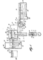
- Figure 1 is a diagrammatic elevation of a long vertical bioreactor system fitted with the head tank by-pass circuit of this invention
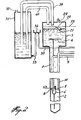
- Figure 2 is a diagrammatic elevation showing an alternative embodiment of the invention.
- a downcomer at 2 a riser, both communicating with a pressurized head tank 3.
- Head tank 3 is fitted with baffle 4 that directs the flow from riser to downcomer across the surface of the head tank.
- Waste water is introduced into riser 2 through influent duct 5.
- the outlet of duct 5 is fitted with an upwardly directed U-shaped exhaust member 6 fitted with a sparger 7 for the injection of an oxygen-containing gas (usually air), into the influent duct.
- the gas serves to oxygenate the waste water and also to form an air lift pump forcing influent into riser 2.
- a second sparger 8 injects an oxygen-containing gas into downcomer 1.
- Feed of waste water to influent duct 5 is from influent trough 9 into which the incoming waste stream (not shown) to be treated is received. Effluent is taken off riser 2 through effluent duct 10 whose inlet is located upstream from the opening of exhaust member 6. The outlet of effluent line 10 discharges tangentially into cylindrical vessel 11 which is fitted with base opening 12 discharging into duct 13 leading to flotation tank 14. Cylindrical vessel 11 has a second exhaust opening 17, controlled by adjustable weir 18. Effluent flowing through 17 passes over weir 18 and chute 19 into inlet trough 9. Relative flow through openings 12 and 17 is controlled by plug valve 20. The position of valve 20 is varied in response to changes in level of liquid in head tank 3 as measured by float 21.
- Float 21 is carried by arm 22 to rotatable shaft 23. To the external end of shaft 23 is attached bell crank 24, the end of bell crank 24 being connected to rod 25 supporting plug valve 20.
- plug valve 20 rises increasing the discharge of effluent to flotation tank 14.
- Flotation tank 14 is fitted with two scrapers 26 and 27. Scraper 26 transfers floating sludge to influent trough 9 for transfer to and further treatment in the bioreactor. Likewise scraper 27 transfers sedimented material to trough 28 from which it in turn is pumped by means not shown to influent trough 9.
- Pressurized head tank 3 is shown fitted with a pressure relief valve 29 but gas and foam present in tank 3 is normally vented through vent duct 30.
- Duct 30 discharges below the level of the waste liquid in collecting vessel 31 thus maintaining a back pressure on head tank 3.
- Collecting vessel 31 is fitted with gas vent 32. Liquid collecting in vessel 31 as the result of the collapse of foam carried over from the head tank can overflow through line 33 by way of overflow pot 34 emptying into line 35 that discharges into influent trough 9. Thus the contents of vessel 31 are recycled through the bioreactor.
- the means for controlling surges of liquid in the bioreactor and in head tank 3 is liquid-venting duct 36.
- Duct 36 has its inlet located at the normal operating liquid level in head tank 3.
- the outlet of liquid-venting duct 36 is positioned below the outlet of gas-venting tube 30.
- Surges of liquid to head tank 3 thus will pass through liquid-venting duct 36 to vessel 31 and will normally then overflow through lines 33 and 35 to influent trough 9.
- tank 31 is fitted with an auxiliary overflow duct 37 discharging into secondary tank 38.
- overflow duct 37 is submerged beneath the liquid level in collecting vessel 31 in order to prevent floating foam from passing to the secondary tank.
- liquid can be fed gradually by conduit means (not shown) to influent trough 9 thereby smoothing the effect of surges in influent flow.
- FIG. 2 a second embodiment of the liquid venting duct is shown in which the connection between head tank 3 and adjacent collecting vessel 31 - is by twin inverted J-shaped pipes 39 and 40.
- the short arm of pipe 39 is connected to the top of head tank 3 and has an arm that descends to a predetermined distance above the normal level of liquid in the head tank.
- the long arm of pipe 39 is immersed in liquid in adjacent collecting vessel 31.
- the short arm of pipe 40 is also connected to the top of head tank 3 but with its opening above the opening of the short arm of pipe 39.
- the long arm of pipe 40 is immersed in liquid in adjacent collecting vessel 31 with its opening located below the opening of the long arm of pipe 39.
- the difference in back pressure is equivalent to the difference in head between the submerged openings of pipes 39 and 40.
- the improved apparatus of this invention smooths out the effects of surges of influent flow by the device of sending excess liquid from the head tank back to the influent stream bypassing the normal route through the downcomer/riser circuit.
- Central of surges in flow has the additional advantage of simplifying the operating of the valve controlling flow in the effluent line.
- the two inverted J-tubes 39 and 40 were installed as follows: Tube 39 was 20 cm diameter and tube 40 was 15 cm diameter and tube 40 had 46 cm greater submergence depth in vessel 31 than tube 39.
- J-tube 39 was 7.6 cm longer than tube 40 and both ends of each tube had sawtooth shaped ends 15 cm long from root to crest. Influent was introduced to the bioreactor at the rate of 6.8 I/s which flow was sufficient to maintain a level in head tank 3 of 76 cm with 2.5 cm submergence on the teeth of the head tank end of J-tube 39.
- Inflow was rapidly increased by adjusting a gate of the influent pipe (less than 30 seconds) to approximately 10.5 I/s at time 0.
- the head tank level rose gradually over a period of 10 minutes from 76 cm to 91 cm thereby choking off air flow in tube 39.
- the air flow was thereby transferred to exposed tube 40.
- head tank pressure rose from 7.6 kPa (gauge) to 12.1 kPa (gauge) in 4 minutes.
- An outflow response to changing head tank pressure was measured on the effluent take-off line 10. The desired peak of 10.5 I/s was reached in 8 minutes.
- the influent channel backed up due to increased internal pressure in the bioreactor shaft and due to increased hydraulic loss due to flow change.
- the datum for the level in the influent channel is 185 cm below head tank bottom.
- the influent trough level rose 124 cm over a period of 25 minutes.
Landscapes
- Life Sciences & Earth Sciences (AREA)
- Organic Chemistry (AREA)
- Engineering & Computer Science (AREA)
- Environmental & Geological Engineering (AREA)
- Water Supply & Treatment (AREA)
- Chemical & Material Sciences (AREA)
- Hydrology & Water Resources (AREA)
- Biodiversity & Conservation Biology (AREA)
- Microbiology (AREA)
- Health & Medical Sciences (AREA)
- Molecular Biology (AREA)
- Apparatus Associated With Microorganisms And Enzymes (AREA)
- Biological Treatment Of Waste Water (AREA)
Applications Claiming Priority (2)
| Application Number | Priority Date | Filing Date | Title |
|---|---|---|---|
| CA338540 | 1979-10-26 | ||
| CA338,540A CA1115433A (en) | 1979-10-26 | 1979-10-26 | Method for protecting a bioreactor pressurized head tank against extreme surges of influent waste water |
Publications (2)
| Publication Number | Publication Date |
|---|---|
| EP0028094A1 EP0028094A1 (en) | 1981-05-06 |
| EP0028094B1 true EP0028094B1 (en) | 1984-02-15 |
Family
ID=4115448
Family Applications (1)
| Application Number | Title | Priority Date | Filing Date |
|---|---|---|---|
| EP19800303625 Expired EP0028094B1 (en) | 1979-10-26 | 1980-10-14 | Long vertical shaft bioreactor and method of protecting it against extreme surges of influent waste water |
Country Status (12)
| Country | Link |
|---|---|
| US (1) | US4272379A (cg-RX-API-DMAC10.html) |
| EP (1) | EP0028094B1 (cg-RX-API-DMAC10.html) |
| JP (1) | JPS5685282A (cg-RX-API-DMAC10.html) |
| AU (1) | AU530643B2 (cg-RX-API-DMAC10.html) |
| CA (1) | CA1115433A (cg-RX-API-DMAC10.html) |
| DE (1) | DE3066622D1 (cg-RX-API-DMAC10.html) |
| ES (1) | ES8203067A1 (cg-RX-API-DMAC10.html) |
| FI (1) | FI70874C (cg-RX-API-DMAC10.html) |
| IN (1) | IN154756B (cg-RX-API-DMAC10.html) |
| NO (1) | NO803153L (cg-RX-API-DMAC10.html) |
| NZ (1) | NZ195327A (cg-RX-API-DMAC10.html) |
| ZA (1) | ZA806352B (cg-RX-API-DMAC10.html) |
Families Citing this family (43)
| Publication number | Priority date | Publication date | Assignee | Title |
|---|---|---|---|---|
| CA2101670A1 (en) * | 1992-08-17 | 1994-02-18 | Michael Ernest Garrett | Treatment of liquids |
| US5650070A (en) * | 1996-03-14 | 1997-07-22 | Deep Shaft Technology Inc. | Aerobic long vertical shaft bioreactors |
| US5645726A (en) * | 1996-03-14 | 1997-07-08 | Deep Shaft Technology Inc. | Treatment of waste liquor in a vertical shaft bioreactor |
| US5660724A (en) * | 1996-05-28 | 1997-08-26 | Deep Shaft Technology Inc. | Multi-pressure head tank for use with vertical shaft bioreactors |
| US5958256A (en) * | 1997-06-04 | 1999-09-28 | Tetra Technologies, Inc. | Method for pretreating an industrial wastewater |
| EP1363857A2 (en) * | 2001-02-23 | 2003-11-26 | V.A.I. Ltd. | Methods and apparatus for biological treatment of waste waters |
| AUPR421501A0 (en) * | 2001-04-04 | 2001-05-03 | U.S. Filter Wastewater Group, Inc. | Potting method |
| AUPR692401A0 (en) | 2001-08-09 | 2001-08-30 | U.S. Filter Wastewater Group, Inc. | Method of cleaning membrane modules |
| ATE549075T1 (de) * | 2003-11-14 | 2012-03-15 | Siemens Industry Inc | Verbessertes modulreinigungsverfahren |
| US7674308B2 (en) * | 2004-03-24 | 2010-03-09 | Donaldson Company, Inc. | Filter elements; air cleaner; assembly; and methods |
| WO2005092799A1 (en) * | 2004-03-26 | 2005-10-06 | U.S. Filter Wastewater Group, Inc. | Process and apparatus for purifying impure water using microfiltration or ultrafiltration in combination with reverse osmosis |
| CA2579168C (en) | 2004-09-07 | 2015-06-23 | Siemens Water Technologies Corp. | Membrane filtration with reduced volume cleaning step |
| NZ553742A (en) * | 2004-09-14 | 2010-09-30 | Siemens Water Tech Corp | Methods and apparatus for removing solids from a membrane module |
| CN100548452C (zh) | 2004-09-15 | 2009-10-14 | 西门子水技术公司 | 一种薄膜过滤系统以及控制薄膜过滤系统中积垢的方法 |
| CN100548451C (zh) * | 2004-12-24 | 2009-10-14 | 西门子水技术公司 | 膜过滤系统中的清洗 |
| CA2591580A1 (en) * | 2004-12-24 | 2006-06-29 | Siemens Water Technologies Corp. | Simple gas scouring method and apparatus |
| NZ562786A (en) * | 2005-04-29 | 2010-10-29 | Siemens Water Tech Corp | Chemical clean for membrane filter |
| WO2007001788A1 (en) * | 2005-06-21 | 2007-01-04 | Nanologix, Inc. | System for sustained microbial production of hydrogen gas in a bioreactor utilizing an equalization tank |
| MY146286A (en) | 2005-08-22 | 2012-07-31 | Siemens Industry Inc | An assembly for water filtration using a tube manifold to minimise backwash |
| NZ568167A (en) * | 2005-12-09 | 2010-04-30 | Siemens Water Tech Corp | Reduced backwash volume process |
| US20090001018A1 (en) * | 2006-01-12 | 2009-01-01 | Fufang Zha | Operating Strategies in Filtration Processes |
| US20090255873A1 (en) * | 2006-08-31 | 2009-10-15 | Bruce Gregory Biltoft | Low pressure backwash |
| WO2008051546A2 (en) * | 2006-10-24 | 2008-05-02 | Siemens Water Technologies Corp. | Infiltration/inflow control for membrane bioreactor |
| US8318028B2 (en) | 2007-04-02 | 2012-11-27 | Siemens Industry, Inc. | Infiltration/inflow control for membrane bioreactor |
| US9764288B2 (en) | 2007-04-04 | 2017-09-19 | Evoqua Water Technologies Llc | Membrane module protection |
| CA3058737C (en) | 2007-05-29 | 2022-04-26 | Fufang Zha | Membrane cleaning with pulsed airlift pump |
| AU2009273775B2 (en) | 2008-07-24 | 2014-11-20 | Evoqua Water Technologies Llc | Frame system for membrane filtration modules |
| WO2010019751A1 (en) * | 2008-08-14 | 2010-02-18 | Siemens Water Technologies Corp. | Block configuration for large scale membrane distillation |
| NZ591259A (en) * | 2008-08-20 | 2013-02-22 | Siemens Industry Inc | A hollow membrane filter backwash system using gas pressurised at at least two pressures feed from the down stream side to push water through the filter to clean it |
| AU2010226550A1 (en) * | 2009-03-19 | 2011-10-13 | Colorado State University Research Foundation | Systems and methods for delivery of gases to algal cultures |
| KR20120028348A (ko) * | 2009-06-02 | 2012-03-22 | 지멘스 인더스트리 인코포레이티드 | 펄스형 가스 슬러그와 전면적 폭기에 의한 막 세정 |
| WO2010142673A1 (en) * | 2009-06-11 | 2010-12-16 | Siemens Water Technologies Corp. | Methods for cleaning a porous polymeric membrane and a kit for cleaning a porous polymeric membrane |
| AU2011245709B2 (en) | 2010-04-30 | 2015-06-11 | Evoqua Water Technologies Llc | Fluid flow distribution device |
| EP2618916A4 (en) | 2010-09-24 | 2016-08-17 | Evoqua Water Technologies Llc | LIQUID CONTROL DISTRIBUTOR FOR A MEMBRANE FILTRATION SYSTEM |
| WO2013048801A1 (en) | 2011-09-30 | 2013-04-04 | Siemens Industry, Inc. | Improved manifold arrangement |
| CN103958034B (zh) | 2011-09-30 | 2017-03-22 | 伊沃夸水处理技术有限责任公司 | 隔离阀 |
| JP5905295B2 (ja) * | 2012-02-27 | 2016-04-20 | 三菱重工プラスチックテクノロジー株式会社 | 作動油貯留装置、および、射出成型装置 |
| EP2866922B1 (en) | 2012-06-28 | 2018-03-07 | Evoqua Water Technologies LLC | A potting method |
| US9962865B2 (en) | 2012-09-26 | 2018-05-08 | Evoqua Water Technologies Llc | Membrane potting methods |
| DE112013004713T5 (de) | 2012-09-26 | 2015-07-23 | Evoqua Water Technologies Llc | Membransicherungsvorrichtung |
| AU2013101765A4 (en) | 2012-09-27 | 2016-10-13 | Evoqua Water Technologies Llc | Gas Scouring Apparatus for Immersed Membranes |
| US10427102B2 (en) | 2013-10-02 | 2019-10-01 | Evoqua Water Technologies Llc | Method and device for repairing a membrane filtration module |
| EP3322511B1 (en) | 2015-07-14 | 2022-09-07 | Rohm & Haas Electronic Materials Singapore Pte. Ltd | Aeration device for filtration system |
Family Cites Families (16)
| Publication number | Priority date | Publication date | Assignee | Title |
|---|---|---|---|---|
| US1972962A (en) * | 1933-05-08 | 1934-09-11 | Weber Max | Constant level apparatus |
| GB1025771A (en) * | 1962-07-06 | 1966-04-14 | Whitehead & Poole | Sewage purification installations |
| US3301779A (en) * | 1965-01-22 | 1967-01-31 | New Canadian Processes Ltd | Process for treating cold rolling mill effluent containing oil emulsified in water |
| US3576738A (en) * | 1969-08-04 | 1971-04-27 | Signal Companies The | Process for purification of oil production waste water |
| US3831758A (en) * | 1970-10-15 | 1974-08-27 | Westinghouse Electric Corp | Waste treatment system |
| US3821107A (en) * | 1972-06-14 | 1974-06-28 | C Peoples | Closed circuit domestic sewage treating method |
| GB1473665A (en) * | 1973-05-16 | 1977-05-18 | Ici Ltd | Treatment of biologically-degradable waste |
| IN141354B (cg-RX-API-DMAC10.html) * | 1973-05-16 | 1977-02-19 | Ici Ltd | |
| GB1527731A (en) * | 1975-04-07 | 1978-10-11 | Ici Ltd | Sewage treatment-flotation apparatus |
| GB1540065A (en) * | 1975-07-10 | 1979-02-07 | Ici Ltd | Aerobic biological treatment of wastewater |
| ZA77986B (en) * | 1976-02-27 | 1977-12-28 | Ici Ltd | Treatment of liquids involving gas separation |
| US4069149A (en) * | 1976-05-14 | 1978-01-17 | Idaho Research Foundation, Inc. | Continuous fermentation process and apparatus |
| GB1573907A (en) * | 1976-05-14 | 1980-08-28 | Ici Ltd | Method and apparatus for the aerobic treatment of waste water |
| DE2625415A1 (de) * | 1976-06-05 | 1977-12-08 | Erwin Dr Ing Schnitzler | Verfahren und anlage zur reinigung von abwasser nach dem belebtschlammverfahren |
| US4137062A (en) * | 1976-12-20 | 1979-01-30 | Great Circle Associates | Filtration with a compostable filter medium |
| US4217211A (en) * | 1979-07-09 | 1980-08-12 | BioMass Fuel Conversion Associates, Inc. | Pressurized treatment of sewage |
-
1979
- 1979-10-26 CA CA338,540A patent/CA1115433A/en not_active Expired
-
1980
- 1980-06-13 US US06/159,349 patent/US4272379A/en not_active Expired - Lifetime
- 1980-10-14 DE DE8080303625T patent/DE3066622D1/de not_active Expired
- 1980-10-14 EP EP19800303625 patent/EP0028094B1/en not_active Expired
- 1980-10-15 ZA ZA00806352A patent/ZA806352B/xx unknown
- 1980-10-15 IN IN759/DEL/80A patent/IN154756B/en unknown
- 1980-10-21 AU AU63530/80A patent/AU530643B2/en not_active Ceased
- 1980-10-21 NZ NZ19532780A patent/NZ195327A/xx unknown
- 1980-10-23 NO NO803153A patent/NO803153L/no unknown
- 1980-10-24 FI FI803340A patent/FI70874C/fi not_active IP Right Cessation
- 1980-10-24 JP JP14826380A patent/JPS5685282A/ja active Pending
- 1980-10-24 ES ES496239A patent/ES8203067A1/es not_active Expired
Also Published As
| Publication number | Publication date |
|---|---|
| DE3066622D1 (en) | 1984-03-22 |
| ES496239A0 (es) | 1982-03-01 |
| US4272379A (en) | 1981-06-09 |
| FI70874C (fi) | 1986-10-27 |
| ES8203067A1 (es) | 1982-03-01 |
| JPS5685282A (en) | 1981-07-11 |
| ZA806352B (en) | 1981-11-25 |
| NZ195327A (en) | 1983-12-16 |
| FI803340L (fi) | 1981-04-27 |
| AU530643B2 (en) | 1983-07-21 |
| FI70874B (fi) | 1986-07-18 |
| EP0028094A1 (en) | 1981-05-06 |
| CA1115433A (en) | 1981-12-29 |
| IN154756B (cg-RX-API-DMAC10.html) | 1984-12-15 |
| NO803153L (no) | 1981-04-27 |
| AU6353080A (en) | 1981-08-20 |
Similar Documents
| Publication | Publication Date | Title |
|---|---|---|
| EP0028094B1 (en) | Long vertical shaft bioreactor and method of protecting it against extreme surges of influent waste water | |
| US4287070A (en) | Method maintaining a constant gas to solids ratio in effluent from a long vertical shaft bioreactor | |
| US4246111A (en) | Apparatus for biological treatment of waste water | |
| US4596658A (en) | Sequencing batch reactor decanter systems | |
| US4883602A (en) | Decanting apparatus and method | |
| CS210625B2 (en) | Method of sewage biological treatment by aeration and equipment for making the same | |
| US4279754A (en) | Means for separation of gas and solids from waste mixed liquor | |
| US4622147A (en) | Plant for the anaerobic purification of waste water | |
| EP2552838B1 (en) | Method of wastewater treatment and apparatus for its realization in sequencing batch reactors | |
| US4512895A (en) | Pumpless clarifier apparatus and process for operation thereof in combination with a draft tube circulator/aerator | |
| US5282487A (en) | Flow control system | |
| GB2374297A (en) | Dynamic sedimentation system | |
| JP2019526441A (ja) | 可変な水柱を備えた嫌気性浄化装置 | |
| US4452701A (en) | Biological treatment of sewage | |
| US3374893A (en) | Sewage purification plant | |
| CA1114962A (en) | Long vertical shaft bioreactor of simplified design | |
| US5264130A (en) | Method and apparatus for recirculation of liquids | |
| US5665236A (en) | Purification of liquids | |
| CN208649085U (zh) | 一种污泥回流装置 | |
| CN108473350B (zh) | 顺序生物反应器和使用该反应器的方法 | |
| CA2038523A1 (en) | Sludge transfer systems and methods | |
| GB1602832A (en) | Apparatus for the treatment of aqueous waste material having a biochemical oxygen demand | |
| NL8302527A (nl) | Inrichting voor het biologisch reinigen van water. | |
| JPS6391109A (ja) | 注水式集水装置 | |
| SU937351A1 (ru) | Устройство дл биохимической очистки сточных вод |
Legal Events
| Date | Code | Title | Description |
|---|---|---|---|
| PUAI | Public reference made under article 153(3) epc to a published international application that has entered the european phase |
Free format text: ORIGINAL CODE: 0009012 |
|
| AK | Designated contracting states |
Designated state(s): BE CH DE FR GB IT NL SE |
|
| 17P | Request for examination filed |
Effective date: 19810918 |
|
| ITF | It: translation for a ep patent filed | ||
| GRAA | (expected) grant |
Free format text: ORIGINAL CODE: 0009210 |
|
| AK | Designated contracting states |
Designated state(s): BE CH DE FR GB IT LI NL SE |
|
| ET | Fr: translation filed | ||
| REF | Corresponds to: |
Ref document number: 3066622 Country of ref document: DE Date of ref document: 19840322 |
|
| PGFP | Annual fee paid to national office [announced via postgrant information from national office to epo] |
Ref country code: FR Payment date: 19840911 Year of fee payment: 5 |
|
| PGFP | Annual fee paid to national office [announced via postgrant information from national office to epo] |
Ref country code: CH Payment date: 19840917 Year of fee payment: 5 |
|
| PGFP | Annual fee paid to national office [announced via postgrant information from national office to epo] |
Ref country code: DE Payment date: 19840924 Year of fee payment: 5 |
|
| PGFP | Annual fee paid to national office [announced via postgrant information from national office to epo] |
Ref country code: SE Payment date: 19840930 Year of fee payment: 5 Ref country code: BE Payment date: 19840930 Year of fee payment: 5 |
|
| PLBE | No opposition filed within time limit |
Free format text: ORIGINAL CODE: 0009261 |
|
| STAA | Information on the status of an ep patent application or granted ep patent |
Free format text: STATUS: NO OPPOSITION FILED WITHIN TIME LIMIT |
|
| 26N | No opposition filed | ||
| PGFP | Annual fee paid to national office [announced via postgrant information from national office to epo] |
Ref country code: NL Payment date: 19861031 Year of fee payment: 7 |
|
| PG25 | Lapsed in a contracting state [announced via postgrant information from national office to epo] |
Ref country code: SE Effective date: 19871015 |
|
| PG25 | Lapsed in a contracting state [announced via postgrant information from national office to epo] |
Ref country code: LI Effective date: 19871031 Ref country code: CH Effective date: 19871031 Ref country code: BE Effective date: 19871031 |
|
| BERE | Be: lapsed |
Owner name: CIL INC. Effective date: 19871031 |
|
| PG25 | Lapsed in a contracting state [announced via postgrant information from national office to epo] |
Ref country code: NL Effective date: 19880501 |
|
| NLV4 | Nl: lapsed or anulled due to non-payment of the annual fee | ||
| GBPC | Gb: european patent ceased through non-payment of renewal fee | ||
| PG25 | Lapsed in a contracting state [announced via postgrant information from national office to epo] |
Ref country code: FR Free format text: LAPSE BECAUSE OF NON-PAYMENT OF DUE FEES Effective date: 19880630 |
|
| REG | Reference to a national code |
Ref country code: CH Ref legal event code: PL |
|
| PG25 | Lapsed in a contracting state [announced via postgrant information from national office to epo] |
Ref country code: DE Effective date: 19880701 |
|
| REG | Reference to a national code |
Ref country code: FR Ref legal event code: ST |
|
| PG25 | Lapsed in a contracting state [announced via postgrant information from national office to epo] |
Ref country code: GB Effective date: 19881118 |
|
| EUG | Se: european patent has lapsed |
Ref document number: 80303625.0 Effective date: 19880707 |