EP0028088B1 - Method, apparatus and spray nozzle for coating the inner surface of long tubes of small diameter - Google Patents
Method, apparatus and spray nozzle for coating the inner surface of long tubes of small diameter Download PDFInfo
- Publication number
- EP0028088B1 EP0028088B1 EP19800303602 EP80303602A EP0028088B1 EP 0028088 B1 EP0028088 B1 EP 0028088B1 EP 19800303602 EP19800303602 EP 19800303602 EP 80303602 A EP80303602 A EP 80303602A EP 0028088 B1 EP0028088 B1 EP 0028088B1
- Authority
- EP
- European Patent Office
- Prior art keywords
- nozzle
- tube
- paint
- coating
- liquid coating
- Prior art date
- Legal status (The legal status is an assumption and is not a legal conclusion. Google has not performed a legal analysis and makes no representation as to the accuracy of the status listed.)
- Expired
Links
Images

Classifications
-
- B—PERFORMING OPERATIONS; TRANSPORTING
- B05—SPRAYING OR ATOMISING IN GENERAL; APPLYING FLUENT MATERIALS TO SURFACES, IN GENERAL
- B05B—SPRAYING APPARATUS; ATOMISING APPARATUS; NOZZLES
- B05B7/00—Spraying apparatus for discharge of liquids or other fluent materials from two or more sources, e.g. of liquid and air, of powder and gas
- B05B7/02—Spray pistols; Apparatus for discharge
- B05B7/10—Spray pistols; Apparatus for discharge producing a swirling discharge
-
- B—PERFORMING OPERATIONS; TRANSPORTING
- B05—SPRAYING OR ATOMISING IN GENERAL; APPLYING FLUENT MATERIALS TO SURFACES, IN GENERAL
- B05B—SPRAYING APPARATUS; ATOMISING APPARATUS; NOZZLES
- B05B13/00—Machines or plants for applying liquids or other fluent materials to surfaces of objects or other work by spraying, not covered by groups B05B1/00 - B05B11/00
- B05B13/06—Machines or plants for applying liquids or other fluent materials to surfaces of objects or other work by spraying, not covered by groups B05B1/00 - B05B11/00 specially designed for treating the inside of hollow bodies
- B05B13/0627—Arrangements of nozzles or spray heads specially adapted for treating the inside of hollow bodies
-
- B—PERFORMING OPERATIONS; TRANSPORTING
- B05—SPRAYING OR ATOMISING IN GENERAL; APPLYING FLUENT MATERIALS TO SURFACES, IN GENERAL
- B05B—SPRAYING APPARATUS; ATOMISING APPARATUS; NOZZLES
- B05B7/00—Spraying apparatus for discharge of liquids or other fluent materials from two or more sources, e.g. of liquid and air, of powder and gas
- B05B7/02—Spray pistols; Apparatus for discharge
- B05B7/06—Spray pistols; Apparatus for discharge with at least one outlet orifice surrounding another approximately in the same plane
- B05B7/062—Spray pistols; Apparatus for discharge with at least one outlet orifice surrounding another approximately in the same plane with only one liquid outlet and at least one gas outlet
- B05B7/066—Spray pistols; Apparatus for discharge with at least one outlet orifice surrounding another approximately in the same plane with only one liquid outlet and at least one gas outlet with an inner liquid outlet surrounded by at least one annular gas outlet
-
- B—PERFORMING OPERATIONS; TRANSPORTING
- B05—SPRAYING OR ATOMISING IN GENERAL; APPLYING FLUENT MATERIALS TO SURFACES, IN GENERAL
- B05B—SPRAYING APPARATUS; ATOMISING APPARATUS; NOZZLES
- B05B7/00—Spraying apparatus for discharge of liquids or other fluent materials from two or more sources, e.g. of liquid and air, of powder and gas
- B05B7/16—Spraying apparatus for discharge of liquids or other fluent materials from two or more sources, e.g. of liquid and air, of powder and gas incorporating means for heating or cooling the material to be sprayed
- B05B7/1606—Spraying apparatus for discharge of liquids or other fluent materials from two or more sources, e.g. of liquid and air, of powder and gas incorporating means for heating or cooling the material to be sprayed the spraying of the material involving the use of an atomising fluid, e.g. air
- B05B7/1613—Spraying apparatus for discharge of liquids or other fluent materials from two or more sources, e.g. of liquid and air, of powder and gas incorporating means for heating or cooling the material to be sprayed the spraying of the material involving the use of an atomising fluid, e.g. air comprising means for heating the atomising fluid before mixing with the material to be sprayed
- B05B7/1633—Spraying apparatus for discharge of liquids or other fluent materials from two or more sources, e.g. of liquid and air, of powder and gas incorporating means for heating or cooling the material to be sprayed the spraying of the material involving the use of an atomising fluid, e.g. air comprising means for heating the atomising fluid before mixing with the material to be sprayed and heat being transferred from the material to be sprayed to the atomising fluid
-
- B—PERFORMING OPERATIONS; TRANSPORTING
- B05—SPRAYING OR ATOMISING IN GENERAL; APPLYING FLUENT MATERIALS TO SURFACES, IN GENERAL
- B05B—SPRAYING APPARATUS; ATOMISING APPARATUS; NOZZLES
- B05B7/00—Spraying apparatus for discharge of liquids or other fluent materials from two or more sources, e.g. of liquid and air, of powder and gas
- B05B7/16—Spraying apparatus for discharge of liquids or other fluent materials from two or more sources, e.g. of liquid and air, of powder and gas incorporating means for heating or cooling the material to be sprayed
- B05B7/1606—Spraying apparatus for discharge of liquids or other fluent materials from two or more sources, e.g. of liquid and air, of powder and gas incorporating means for heating or cooling the material to be sprayed the spraying of the material involving the use of an atomising fluid, e.g. air
- B05B7/1613—Spraying apparatus for discharge of liquids or other fluent materials from two or more sources, e.g. of liquid and air, of powder and gas incorporating means for heating or cooling the material to be sprayed the spraying of the material involving the use of an atomising fluid, e.g. air comprising means for heating the atomising fluid before mixing with the material to be sprayed
- B05B7/1646—Spraying apparatus for discharge of liquids or other fluent materials from two or more sources, e.g. of liquid and air, of powder and gas incorporating means for heating or cooling the material to be sprayed the spraying of the material involving the use of an atomising fluid, e.g. air comprising means for heating the atomising fluid before mixing with the material to be sprayed the material to be sprayed and the atomising fluid being heated by the same source of heat, without transfer of heat between atomising fluid and material to be sprayed
-
- B—PERFORMING OPERATIONS; TRANSPORTING
- B05—SPRAYING OR ATOMISING IN GENERAL; APPLYING FLUENT MATERIALS TO SURFACES, IN GENERAL
- B05B—SPRAYING APPARATUS; ATOMISING APPARATUS; NOZZLES
- B05B7/00—Spraying apparatus for discharge of liquids or other fluent materials from two or more sources, e.g. of liquid and air, of powder and gas
- B05B7/16—Spraying apparatus for discharge of liquids or other fluent materials from two or more sources, e.g. of liquid and air, of powder and gas incorporating means for heating or cooling the material to be sprayed
- B05B7/1606—Spraying apparatus for discharge of liquids or other fluent materials from two or more sources, e.g. of liquid and air, of powder and gas incorporating means for heating or cooling the material to be sprayed the spraying of the material involving the use of an atomising fluid, e.g. air
- B05B7/1613—Spraying apparatus for discharge of liquids or other fluent materials from two or more sources, e.g. of liquid and air, of powder and gas incorporating means for heating or cooling the material to be sprayed the spraying of the material involving the use of an atomising fluid, e.g. air comprising means for heating the atomising fluid before mixing with the material to be sprayed
- B05B7/1646—Spraying apparatus for discharge of liquids or other fluent materials from two or more sources, e.g. of liquid and air, of powder and gas incorporating means for heating or cooling the material to be sprayed the spraying of the material involving the use of an atomising fluid, e.g. air comprising means for heating the atomising fluid before mixing with the material to be sprayed the material to be sprayed and the atomising fluid being heated by the same source of heat, without transfer of heat between atomising fluid and material to be sprayed
- B05B7/1653—Spraying apparatus for discharge of liquids or other fluent materials from two or more sources, e.g. of liquid and air, of powder and gas incorporating means for heating or cooling the material to be sprayed the spraying of the material involving the use of an atomising fluid, e.g. air comprising means for heating the atomising fluid before mixing with the material to be sprayed the material to be sprayed and the atomising fluid being heated by the same source of heat, without transfer of heat between atomising fluid and material to be sprayed the source of heat being a heat conductive fluid
Definitions
- This invention relates to a method, apparatus and spray nozzle for coating the inner surface of long tubes of small diameter, and more particularly to a method applicable to protective coating of a heat exchanger tube or condenser tube employed in a condenser of a steam turbine, used for a power plant, being especially effective in performing the coating where the tube is in an installed condition in the plant, and to an apparatus therefor.
- condensers In power plants condensers have been traditionally used for cooling the exhaust gas (steam) of a stream-turbine to condense it and recycle the condensed water.
- a condenser of such use thousands of or sometimes tens of thousands of long tubes of copper alloy, for example 5-40 m in length, having a small inner diameter on the order of 10-40 mm are incorporated as condenser tubes.
- Those tubes, which pass the cooling water such as sea water therethrough, are adapted to cool the exhaust steam passing thereoutside.
- Those condenser tubes which constantly pass the cooling liquid such as sea water containing corrosive substances richly at a fairly high flow speed, for example 1-2.5 m/sec., are susceptible to various types of corrosion or erosion corrosion. It is therefor necessary to cover or coat the whole inner (internal) surface of those tubes with a protective synthetic resin coating or paint for the purpose of corrosion-and-rust prevention. But the coating in this case is required to avoid degradation of the heat transfer therefrom, which is the essential condition of the condenser tube, by all means.
- a thin (on the order of 10-30 ⁇ ) and uniform coating film which will not deteriorate the heat transferring or exchanging capability is needed for the protective coating of a heat transfer tube such as a heat exchanger tube in a heat changer like a condenser.
- tubes having a thin coating film in the interior thereof it is sometimes necessary to repaint or recoat, before the life of the whole plant for example 20 or 30 years comes to an end, because the thin coated film (a) may be worn away after the tubes being installed in the plant to expose the base metal by a mere aging, (b) may be eroded by shells or sand particles contained in the sea water, or (c) may be worn acceleratively by the so-called sponge ball cleaning method taken to remove foreign matters stuck to the tube such as seaweeds.
- the interior coating of resin paint film of the tubes are sometimes shorter in life than the plant itself, and it must be periodically or occasionally repainted (recoated) particularly in an installed state in the plant.
- paint nebulized or atomized by a spray gun is coated on the inner surface of a tube, and sometimes even a long neck spray gun with a length of 500 mm or so is inserted in the tube, but it is not free from a problem that the length of the tube to be effectively coatable by this spray gun is naturally restricted to some extent.
- Still another method as a variation of the above for avoiding the problem, seems to be available, wherein a moving nozzle which is shiftable from one end of a tube to the other end while spraying the paint is employed.
- a spray gun is provided with an elongated barrel formed of concentric rigid tubes.
- the total length of the barrel is formed by screwing a plurality of barrel sections into one another.
- a rigid control rod extends longitudinally up the centre of the innermost barrel table and terminates in a valve portion having a conical tip. This tip mates with the end of a passage in tubular stem of spray head.
- the stem is located within a cylindrical nozzle cap and is provided with a spiral groove on its outer surface.
- Flow of fluid from the spray gun is controlled in use by moving the control rod backwards and forwards and the spiral groove on the surface of stem imparts a whirling motion to the spray.
- the thickness (t) of a coated film is regulated by an undermentioned formula, wherein,
- the thickness (t) of the film is given as a function of the discharge amount (q) of the paint, solid ratio (a), i.e. of the solidified portion (component to be remained), of the paint, and the shifting rate (v) of the spray nozzle.
- the ratio of the solidified portion of the paint is determined by the mixing ratio of the synthetic resin, pigment, and solvent. Coating is however practiced generally, irrespective of the environmental temperature, at a most suitable paint viscosity for spraying.
- the viscosity of a film forming substance such as synthetic resin depends, on the other hand, upon the temperature, so it is necessary to vary the mixing ratio of the solvent in the paint according to the environmental temperature under which the coating is carried out so as to keep a constant viscosity of the paint to be coated. In other words, the value in the general formula mentioned above is varied to consequently change the thickness (t) of the film.
- Hot spray coating was proposed, on the other hand, to eliminate those disadvantages.
- French Specification FR-E-88147 describes an arrangement for heating the compressed air feed to a spray gun (although there is no suggestion of using the spray gun to coat the internal surfaces of tubes) in which a compressed air supply is divided and fed via flexible tubes to accumulators having electrically heated collars. Heated air is taken from the accumulators via lines and combined in flexible tube, which is provided in its interior with flexible elongated heating elements.
- the air spray coating method in the interior coating of a tube is usually limited to a case wherein the internal diameter of the tube is relatively large, the length of the tube is within 5 meters or so, and the thickness of the coated film is allowed as large as 50-200 u. It is therefore employable only for the anti-corrosion coating of a tube or pipe used in flowing an ordinary fluid.
- a nozzle portion In a spray gun which has been used in the air spray coating, a nozzle portion is said susceptible to sticking of paint and dust in either the paint passage or air passage. Such sticking of paint and dust to the passages is liable to deteriorate the spraying (atomizing) condition due to the clogging thereof. It makes the spraying unstable, which naturally hampers a continuous and uniform coating to be executed smoothly. Besides, the clogging of the essential portions of the nozzle requires a breaking up for cleaning thereof, giving rise to another problem of increasing the man power to be consumed.
- the present invention was made from such a background. It is therefore a primary object of this invention to provide an effective and practical method of coating the inner or internal surface of a long tube of small diameter and an apparatus therefor.
- a method for coating the inner surface of a long tube of small diameter from one end opening of the long tube to the other end opening thereof comprises:
- the invention also provides a coating apparatus for coating the inner surface of a long tube of small diameter by spraying a liquid coating medium in a manner producing atomization while being shifted from one end opening to the other end opening thereof, comprising:
- a nozzle for apparatus for continuously and gradually coating the inner surface of a tube by spraying, while being shifted inside along the axial direction of said tube comprising:
- This invention has enabled the formation of a thin and uniform thick film on the inner surface of a long tube of small diameter, without producing any unevenness and other defects in the coated film.
- the supplying hose is drawn back at a predetermined speed or rate toward the firstly inserted opening end, while performing the paint spraying from the nozzle.
- the paint and the air are respectively delivered from a paint reservoir and a compressed air tank of air-transformer type located outside the long tube through the supplying hose longer than the long tube to be coated; and the paint and the air are respectively heated to a predetermined temperature in the course of being delivered to the nozzle for being sprayed therefrom. It enables the paint to be sprayed under the predetermined atomization condition constantly, eliminating the necessity of varying the solvent ratio for adjusting the viscosity of the paint.
- the atomizing gas is imparted a straight going force and a spiral going force, owing to the axially elongated grooves, between the prism portion and the inside surface of the nozzle cap, and the spiral groove.
- the paint can be, due to the double directional atomizing gas, spirally sprayed with a uniform thickness in the circumferential and axial directionn of the tube-to-be-coated throughout the entire length thereof.
- This nozzle has eliminated the frequent overhauling of the spray nozzle which was conventionally inevitable due to the clogging of paint remnant and dust in the air pocket and other portions of the nozzle.
- This nozzle has enabled in this way a stable and continuous spraying operation for a long tube of small diameter, bringing about a good result of thin and uniform thickness of film in all direction of the tube interior.
- this invention is quite effective.
- This nozzle is capable of giving a coating film at a thickness of 10-30,a to a condenser tube of the above-mentioned dimension, without deteriorating the heat transfer function of the tube at all, the most important feature as a heat exchanger.
- FIG. 1 A surface condenser 10 employed in a thermal power plant (station), being connected with a steam-turbine, is shown in Fig. 1, wherein a large cylindrical fluid-tight, sealable condenser shell 1 is divided into three chambers with a pair of condenser tube plates 2 and 3 disposed at either endwise biased portion. In the central portion sandwiched by the pair of plates 2, 3 thousands of or tens of thousands of condenser tubes 4 of copper alloy with the diameter of 10-40 mm ⁇ are parallelly disposed extending along the length of 5-40 m. On either end portion of the condenser shell 1 outside the tube plates 2, 3 condenser water boxes 6 and 7 is respectively formed.
- a steam inlet 11 is disposed centrally located for receiving the exhaust steam from the steam turbine; on the lower side of the shell 1 a condensed water recovering (receiving) inlet 12 is made, similarly centrally located in the alteral direction, as can be seen in Fig. 1.
- a cooling water outlet 16 is provided on top of the shell 1; in the right side of the water box 7 a cooling water inlet 17 is provided on the lower side of the shell 1.
- a vent 13 is formed on one flank of the shell 1.
- the cooling water inlet 17 and the cooling water outlet 16 are respectively connected to a circulating water pump; the condensed water receiving inlet 12 is connected to a condensate pump; and the vent 13 is connected to an exhaust pump. These pumps are however not shown in the drawings.
- the cooling water in a condenser 10 of this type is flowed through the condenser tubes 4 from right to left in Fig. 1, while the exhaust steam from the steam turbine is passed through the gap left among the condenser tubes 4 almost downwardly on the other hand, so as to perform a heat transference between the cooling water and the exhaust steam through the contact of both at the wall of the condenser tubes with a result of condensing the exhaust steam into water.
- a coating operator enters into one, or both when it is necessary, of the condenser water boxes 6, 7 on the end portion of the condenser 10 for operating the spray nozzle there.
- the operator works in the water box 6, he inserts a supplying hose 22 having a spray nozzle 21 on the tip thereof and respective passages for paint and compressed air into one side opening of a condenser tube 4 and continues to push it deeper therein until the spray nozzle 21 reaches, passing through the whole length (5-40 m) of it, the other end opening of the condenser tube 4 on the side of the water box 7.
- the supplying hose 22 begins to be drawn back with a mechanical means at a predetermined speed, upon starting the spraying of the paint.
- the paint to be sprayed and the compressed air are supplied from a paint reservoir (not shown) and an air transformer (not shown) respectively situated in the water box 6 or outside the condenser 10, through the separate passages.
- the paint is atomized for being sprayed at the nozzle 21 with the aid of the compressed air in a well known way.
- Such a coating process which is susceptible to various environmental conditions, such as temperature, humidity, etc., requires to be maintained at an optimum situation for forming a non-defective and uniform thick film.
- the present invention is aimed at obtaining an optimum spraying conditoin of the paint through nebulization or atomization of the paint at the spray nozzle 21 by means of supplying the paint and the compressed air, through the respective passage in the supplying hose 22, heated at a most preferable temperature for coating such as 15-35°C.
- FIG. 2 What is illustrated in Fig. 2 is an example of electrical heating means, being effective in realizing this invention and extremely simple in structure, wherein a front end portion of a nozzle is shown as an axial sectional view. The paint and the compressed air delivered thereto are heated there up to a predetermined temperature in a very short time.
- a spray nozzle 21 of ordinary structure is provided with a paint passage 21 a in the central part and an air passage 21 b embracing the former completely in it for spraying the paint by the action of the compressed air in atomization state.
- the supplying hose 22 to which the nozzle 21 is attached is composed of a flexible hose 23 of double-structure leading the paint and the compressed air from outside the condenser tube 4 and a metallic heating pipe 24 of a predetermined length for heating the paint and the compressed air delivered thereto by the flexible hose 23.
- the flexible hose 23 is constituted of an inside tube 23a made of polyvinyl chloride or the like for forming a paint route or passage and a flexible outside tube 23b made of hard plastic for example hard nylon or metallic flexible tube being concentric with the inside tube 23a to form an air route or passage therebetween.
- the heating pipe 24 which is attached with a joint. 25 to the tip of the flexible hose 23, just like the latter, of double structure consisting of an inside pipe 24a and an outside pipe 24b.
- the inside pipe 24a is communicated with the inside tube 23a for forming a paint passage and the outside pipe 24b is communicated with the outside tube 23b for forming an air passage.
- a sheathed heater 26 for example sheath element 0.2-1 mm ⁇ and external diameter of the sheath 1.6-4.8 mmo, as an electric heating means is wound like a coil for heating directly the compressed air and indirectly, via a pipe wall of the inside pipe 24a, the paint under the control of a thermostat 27 attached to the tip of the sheathed heater 26.
- Power supply to the sheathed heater 26 is executed by a lead wire 28 extending through the outside tube 23b so far as to get out of the condenser tube 4; and the sheathed heater 26 is covered by a stainless-steel-made tube for being completely separated from the inside pipe 24a for feeding the paint, so there is no likelihood and no danger of a fire or an explosion.
- the above- mentioned heating pipe 24 is, at the tip thereof, connected to the nozzle 21 by way of a joint 29; the inside pipe 24a is connected to a paint passage 21 a of the nozzle 21 and the outside pipe 24b is connected to an air passage 21 b of the nozzle 21.
- the paint and the compressed air delivered from outside the condenser tube 4 through the flexible hose 23 are respectively heated to a predetermined temperature by the sheathed heater 26 at the heating pipe 24 for being immediately led to the nozzle 21, where the heated paint is sprayed in atomization by the action of the similarly heated compressed air.
- the sheathed heater 26 for heating the paint and the compressed air from 5°C to 30°C respectively, under conditions where the compressed air gushing (blowing) amount is 300 I/min. and the paint discharged amount is 100 ml/min and the heater 26 has a length of 360 mm., it has to be maintained at 150°C under the control of the thermostat 27.
- the length of the heating portion with the sheathed heater 26, i.e., the length of the heating pipe 24 may be suitably determined depending upon the compressed air amount, the paint discharge amount, the material quality of the heater's inserting portion, the heating condition, etc., with a variety of choice, for example, from ordinary length of approx. 300 mm to an extremely long case of covering the whole length of the supplying hose 22.
- the same pipe is preferable to be flexible over the whole length from the view point of easiness of its handling, and required to be made of a material sufficiently resistant to a temperatue of 40-60°C. It is effective to employ a heat-resistant plastic for both the inside tube and the outside tube of the supplying hose 22 or employ a metallic flexible tube for the outside tube.
- FIG. 3 another embodiment of this invention, wherein the similar sheathed heater to that in Fig. 2 is employed, is shown.
- a spray nozzle 31 is connected therein by way of a joint 30 to a flexible hose 23 as the supplying hose 22.
- a nozzle insert 31 a with a paint passage in the central part is coaxially threaded, and a nozzle cap 31b is threaded on the external side of the joint 30.
- a gap formed between the nozzle insert 31 a and the nozzle cap 31 b constitutes a passage for the compressed air.
- the outside tube 23b which delivers the compressed air in the flexible hose 23 of double structure, is firmly fitted; and at the same time on a metallic inner tube 30a, which is fitted into a central through-bore of the joint 30, the inside tube 23a for feeding the paint is firmly fitted.
- a sheathed heater 32 is wound about for heating the paint and the compressed air by being supplied with power through a lead wire 28 running along the outside tube 23b, just like in the previous embodiment.
- the outside tube 23b of the flexible hose 23 can be utilized, as it is, as an outside tube to the inner tube 30a, advantageously eliminating the putting of a separate metallic pipe as in Fig. 2.
- FIG. 4 Still another embodiment with an electrical heating means such as a sheathed heater is shown in Fig. 4, wherein a flexible hose 23 as the supplying hose 22 is, unlike the previous ones, of triple structure. Between an inside tube 23a and an outside tube 23b a median tube 23c is coaxially disposed. On the external surface of the inside tube 23a a sheathed heater 33 is wound about, while a gap formed between the inside tube 23a and the median tube 23C is filled with a suitable heat conducting medium such as air, water, etc., which functions along with a sheathed heater 33 to heat the paint fed through the inside tube 23a and the compressed air fed through the outside tube 23b respectively _to a predetermined temper- atu re.
- a suitable heat conducting medium such as air, water, etc.
- the paint and the compresed air in the flexible tube 23 are maintained at a suitable temperature, even when the coating operation is temporarily suspended and the heating with the sheathed heater 33 is stopped by any chance, by the heat kept in the heat conducting medium.
- the paint and the compressed air are advantageously protected from being affected by the ambient conditions immediately.
- This structure is particularly useful in a system wherein the heating means is disposed ranging the whole length of the supplying hose 22.
- a flexible hose 40 which extends from outside of the condenser tube 4 to a predetermined position in the condenser tube 4, is constituted of an outside tube 41 of hard plastic for forming a compressed air passage 41 a, a median tube 42 for forming a paint passage 42a, and an inside tube 43 of heat-resistant plastic for forming a passage (forward and backward) for heated fluid.
- an outside tube 41 of hard plastic for forming a compressed air passage 41 a
- a median tube 42 for forming a paint passage 42a
- an inside tube 43 of heat-resistant plastic for forming a passage (forward and backward) for heated fluid.
- Three of these are all coaxially arranged to make a triple structure.
- a long partition is disposed in a diametric direction ranging the whole length of the tube to divide the inside into two parts, i.e., forward flowing passage 43a and a backward flowing passage 43b.
- a spray nozzle 46 is attached by way of a suitable joint 45.
- the inside tube 43 is not blocked by the joint 45, but the forward flowing passage 43a and the backward flowing passage 43b thereof are communicated to each other only in the end portion, that is, in the attaching portion of the spray nozzle 46. Accordingly, warm and heated water from a water supplying tank similarly disposed as the paint reservoir outside the condenser tube, or heated air (or other heated fluid) from a suitable heating means comes through the inside tube 43, specifically through the forward flowing passage 43a, to the vicinity of the attaching portion of the spray nozzle 46, where it is flowed back through the backward flowing passage 43b to outside of the condenser tube 4.
- the amount of the medium used in the cylcing is, in contrast to the amount of the medium in a direct heating type hot air system, small and economical because of a possible small size of the heater capacity, outside the condenser tube 4.
- a metallic heating tube of small length like one in Fig. 2 designated with 24, is attached in the above embodiment to a portion adjacent to the nozzle 46, the paint and the compressed air will be further stabilized in their required temperature.
- the same object can be attained by incorporating a sheath heater in the inside tube 43 and by cycling only the air therethrough.
- FIG. 7 Another example of heating by means of heated fluid can be seen in Fig. 7 or Fig. 8, either being effective.
- a pair of small diametered tubes 51, 52 of heat resistant vinyl resin are respectively inserted into a pair of sections 50a, 50b formed in the flexible hose 50.
- 51 is adapted to pass the paint and the other may be adapted for passing the compresed air; and one section 50a. is used as a forward flowing passage for the heating medium and the other section 50b as a backward fluid passage of the same.
- sheathed heaters may be wound about each of the small diametered tubes 51, 52 in a coil style ranging the whole length of the tube for heating the paint and the compressed air.
- a supplying hose 53 is divided into four sections, one pair of diagonally positioned sections 53a, 53c are used for the paint and the compressed air feeding, and the other diagonally positioned sections 53b, 53d are used for the forward flowing passage and the backward flowing passage of the heating medium.
- Those supplying hoses 50, 53 are all connected via a suitable joint to a spray nozzle, and the heating medium is flowed through a forward flowing passage (50a, 53b), which is respectively one of the passages in the supplying hose, up to the vicinity of the connecting portion of the spray nozzle, where it is flowed back through respective backward flowing passage (50b, 53d) outside the system. While the heating medium is thus cycled from the forward flowing passage to the backward flowing passage, the paint and the compressed air are respectively heated, by way of the tube or hose wall, up to a predetermined temperature, so that the paint may be sprayed by the compressed air in a good spraying condition.
- a spray gun preferably employable in the present invention is provided with a cylindrical outer casing 61, which is on either male-screwed end portions thereof threaded by a center guide 62 and 63, as illustrated in Fig. 9.
- the center guides 62 and 63 are all of hexagonal form in cross section, having a dimension just inscribable in the inner surface of a tube-to-be-coated.
- the hexagonal edge portions of the center guides 62, 63 are good for guiding the spray gun itself by being slided reciprocally along the inside of the tube.
- a nozzle cap 64 is concentrically fastened thereto at a flange 64a thereof by the center guide 62.
- An inner casing 65 having an external diameter smaller than the internal diameter of the outer casing 61 by a predetermined amount is disposed inside, and concentrically with, the outer casing 61.
- a nozzle insert 68 having a through bore 68a in the axis thereof is threaded into.
- a sheathed heater, as not shown, such as that illustrated in Fig. 2 is wound about on the external surface of the inner casing 65.
- the nozzle insert 68 is provided with a hexagonal prism portion 68b which is inscribable in a hollow cylindrical portion 64b of the nozzle cap 64 and a conical portion 68c faced to a hollow conical space 64c of the nozzle cap 64 with a predetermined gap.
- a hexagonal prism portion 68b which is inscribable in a hollow cylindrical portion 64b of the nozzle cap 64 and a conical portion 68c faced to a hollow conical space 64c of the nozzle cap 64 with a predetermined gap.
- six straight but arch ceiling shaped spaces 69 are left lengthwise as seen in Fig. 12; on the surface of the nozzle insert 68 a spiral groove 70 is inscribed with a certain angle a to the axis thereof, as can be seen in Figs. 13 and 14.
- the left end (in Fig. 9) of the inner casing 65 is threaded in a boss 61 a of the outer casing 61 as to leave a predetermined space 71 between the inner casing 65 and the outer casing 61.
- a passage for the atomizing (spraying) gas is amde in the direction toward the nozzle cap 64.
- the atomizing gas is supplied by an air hose 76 attached to the open end of the center guide 63; the air hose 76 is usually made into a double hose 75, i.e.
- a supplying hose containing a paint supply passage 66 therein, for being inserted deep into, and drawn back out of a tube to be coated.
- the boss 61 a is provided with a fitting 67 threaded thereinto, to the other end thereof the paint supply passage 66 is intended to be connected.
- the fitting 67, the inner casing 65, and the through-bore 68a in the nozzle insert 68 constitute a route for supplying the paint.
- the paint is supplied through an inside route of a double tube formed by the center guide 63 and the fitting 67, and atomizing gas led by the air hose 76 is supplied through an outside route of the double tube.
- the paint coming through the fitting 67, the inner casing 65, and the through-bore 68a of the nozzle insert 68 is sprayed out of a tip portion 73 of the through-bore 68a; and the blowing gas such as compressed air is led forward through the through-holes 61 b and the space 71, and is further given a straight going force in the straight grooves 69 and a spirally advancing force through the spiral groove 70, before it is blown, getting through the space between the conical portion 68c of the nozzle insert 68 and the hollow conical space 64c of the nozzle cap 64, out of a gas blowing portion 72.
- This blowing (or spraying) gas atomizes the paint gushing out of the tip portion 73 of the through-bore 68a of the nozzle insert 68, while spiraling the same, which enables the paint to be sprayed uniformly toward the inner surface of the tube-to-be-coated.
- a double hose 75 having a spray nozzle 80 of this invention on the tip thereof, is inserted into the condenser tube 81 from one end opening 81 a thereof as far as the other end opening 81 b throughout the whole length (5-40 m) of the condenser tube 81.
- the moment when the spray nozzle 80 has reached the other end opening 81 b of the condenser tube 81 spraying of the paint is commenced with atomization.
- the paint and the atomizing gas are independently supplied through their respective passage, as mentioned above, before reaching the spray nozzle 80, where the former is sprayed in atomization due to the double directional spraying force of the latter, i.e., straight and spiral.
- the double hose 75 is drawn back while spraying the paint from the spray nozzle 80, by means of a suitable mechanical means, at a predetermined constant speed from the other end opening 81 b toward the one end opening 81 a of the condenser tube 81.
- the inner surface thereof is gradually and regularly coated with the atomized paint.
- the whole length of the condenser tube 81 can thus be coated with a uniform thickness from one end to the other end thereof.
- the spray nozzle 80 has returned to the one end opening 81 a, the supplying of the paint and the atomizing gas is suspended to stop the coating operation.
- one condenser tube 81 is finished coating in this way another and a third tube will be coated in order successively in a similar way.
- a condenser having a large number of condenser tubes can be coated or re-coated on the inner surface thereof quite smoothly and effectively.
- the shape of the spiral groove or grooves 70 formed (inscribed) on the external surface of the nozzle insert 68 may be varied according to the internal diameter of the condenser tube 81 to be coated. It is appropriate in normal cases to determine the twist angle ⁇ formed between the spiral groove 70 and the axis of the nozzle insert 68 (see Fig. 13) in the range of 15-60°. And it is preferable to set the spray angle 0, that is a half of the vertical angle of the conical portion 68c of the nozzle insert 68, within the range of 5-45° so as to ensure the best spraying condition at a place 200 mm distant from the tip of the spray nozzle 80.
- the nozzle insert 68 is provided with the hexagonal prism portion 68b which is easy in machining, but the shape of this prism portion is by no means limited to the hexagon. It is of course variable in various suitable ways to those skilled in the art, for example, quadrangular or octangular prism and so on, without any difficulty.
- the paint used was:
- the coating conditions were:
- the result may be said surprisingly excellent considering the severe conditions under which the coating was carried out.
Landscapes
- Nozzles (AREA)
Description
- This invention relates to a method, apparatus and spray nozzle for coating the inner surface of long tubes of small diameter, and more particularly to a method applicable to protective coating of a heat exchanger tube or condenser tube employed in a condenser of a steam turbine, used for a power plant, being especially effective in performing the coating where the tube is in an installed condition in the plant, and to an apparatus therefor.
- In power plants condensers have been traditionally used for cooling the exhaust gas (steam) of a stream-turbine to condense it and recycle the condensed water. In a condenser of such use thousands of or sometimes tens of thousands of long tubes of copper alloy, for example 5-40 m in length, having a small inner diameter on the order of 10-40 mm are incorporated as condenser tubes. Those tubes, which pass the cooling water such as sea water therethrough, are adapted to cool the exhaust steam passing thereoutside.
- Those condenser tubes, which constantly pass the cooling liquid such as sea water containing corrosive substances richly at a fairly high flow speed, for example 1-2.5 m/sec., are susceptible to various types of corrosion or erosion corrosion. It is therefor necessary to cover or coat the whole inner (internal) surface of those tubes with a protective synthetic resin coating or paint for the purpose of corrosion-and-rust prevention. But the coating in this case is required to avoid degradation of the heat transfer therefrom, which is the essential condition of the condenser tube, by all means. For example a thin (on the order of 10-30 µ) and uniform coating film which will not deteriorate the heat transferring or exchanging capability is needed for the protective coating of a heat transfer tube such as a heat exchanger tube in a heat changer like a condenser.
- With tubes having a thin coating film in the interior thereof it is sometimes necessary to repaint or recoat, before the life of the whole plant for example 20 or 30 years comes to an end, because the thin coated film (a) may be worn away after the tubes being installed in the plant to expose the base metal by a mere aging, (b) may be eroded by shells or sand particles contained in the sea water, or (c) may be worn acceleratively by the so-called sponge ball cleaning method taken to remove foreign matters stuck to the tube such as seaweeds. The interior coating of resin paint film of the tubes are sometimes shorter in life than the plant itself, and it must be periodically or occasionally repainted (recoated) particularly in an installed state in the plant.
- Conventionally practiced methods, mostly used for painting the interior of relatively short tubes ranging the whole length thereof, that is, flow coating method of flowing paint through a tube or brush coating method of brushing paint directly on the inner surface of the tube, have been defective for being applied to long tubes of small diameter in being difficult in getting a uniform-thick coated film. Particularly the former method is not good when it is applied to a tube already installed in a condenser, because the tube can not be inclined for flowing out the superfluous paint. Practicability of both the methods are as a matter of fact hardly recognized at the present stage.
- As another method with relatively high practicability and which seems to be available, paint nebulized or atomized by a spray gun is coated on the inner surface of a tube, and sometimes even a long neck spray gun with a length of 500 mm or so is inserted in the tube, but it is not free from a problem that the length of the tube to be effectively coatable by this spray gun is naturally restricted to some extent. Still another method, as a variation of the above for avoiding the problem, seems to be available, wherein a moving nozzle which is shiftable from one end of a tube to the other end while spraying the paint is employed.
- The previously known techniques may be illustrated by US Patent US-A-2,520,397, in which a spray gun is provided with an elongated barrel formed of concentric rigid tubes. The total length of the barrel is formed by screwing a plurality of barrel sections into one another. A rigid control rod extends longitudinally up the centre of the innermost barrel table and terminates in a valve portion having a conical tip. This tip mates with the end of a passage in tubular stem of spray head. The stem is located within a cylindrical nozzle cap and is provided with a spiral groove on its outer surface.
- Flow of fluid from the spray gun is controlled in use by moving the control rod backwards and forwards and the spiral groove on the surface of stem imparts a whirling motion to the spray.
- In these prior techniques, problems are still left unsolved as to what length of the tube interior can be well coated by the spray coating method. Even the latter, when it is applied to coating of the interior of a condenser tube of small diameter and large length, particularly in a heat exchanger tube of a condenser, leaves something to be desired. For example, as the coated film is apt to be largely influenced by temperature, humidity and other environmental conditions, it is very difficult to keep the film thickness at a desired uniform value in coating an already installed long tubes of small diameter where the necessary environmental conditions are almost out of control; uneven thickness or defective coating of the tilm may as a result take place there. When the tube to be coated is a long heat exchanger tube, varying of the thickness of the coated film is likely to cause variation of the heat conducting or transferring capability. So strict control of the environmental conditions for keeping the coating thickness even is of great importance.
- Generally the thickness (t) of a coated film is regulated by an undermentioned formula,

- q: discharge amount of the paint
- α: solid ratio of the paint
- Di: inner diameter of the tube to be coated
- v: shifting rate of the spray nozzle
- p: density of the coated film.
- That is to say, the thickness (t) of the film is given as a function of the discharge amount (q) of the paint, solid ratio (a), i.e. of the solidified portion (component to be remained), of the paint, and the shifting rate (v) of the spray nozzle. Out of those (q) and (v) can be easily made constant independently of the environmental conditions of coating, but (a), the ratio of the solidified portion of the paint, is determined by the mixing ratio of the synthetic resin, pigment, and solvent. Coating is however practiced generally, irrespective of the environmental temperature, at a most suitable paint viscosity for spraying. The viscosity of a film forming substance such as synthetic resin depends, on the other hand, upon the temperature, so it is necessary to vary the mixing ratio of the solvent in the paint according to the environmental temperature under which the coating is carried out so as to keep a constant viscosity of the paint to be coated. In other words, the value in the general formula mentioned above is varied to consequently change the thickness (t) of the film.
- Observing this problem from the view point of defects of the coated film, operation in the plants in cold districts or in a winter season draws particular attention. The solvent ratio must inevitably be raised in such cases because of the remarkable low level of the ambient temperature for getting the predetermined viscosity of the plant. This consequently results in occurrence of dripping or gathering of the paint toward the lower side of the tube due to elongation of the film forming time duration, insufficient curing of the coated film, remelting of the once solidified film in response to increasing of the solvent evaporating amount, and undesirable environmental pollution due to the evaporation of the solvent in large quantity.
- Hot spray coating was proposed, on the other hand, to eliminate those disadvantages.
- French Specification FR-E-88147 describes an arrangement for heating the compressed air feed to a spray gun (although there is no suggestion of using the spray gun to coat the internal surfaces of tubes) in which a compressed air supply is divided and fed via flexible tubes to accumulators having electrically heated collars. Heated air is taken from the accumulators via lines and combined in flexible tube, which is provided in its interior with flexible elongated heating elements.
- As demonstrated by French Specification FR-E-88147, traditional technology involves heating the paint or the air employed at the source thereof, be it by the paint heating method or the hot air spray method of the aforementioned French specification and is very impracticable from the view point of applying the same to the inner surface of long tubes of smaller diameter. This is because, in the condenser tubes of large length already installed in a condenser or the like the distance from the paint reservoir to the end of the spray nozzle is not less than 20 m at the least, and consequently maintaining the temperature of the paint at a predetermined level is difficult. In case of the hot air spraying method, supply of the required hot air of large quantity, such as 200-5001/min., passing such a long distance, needs a huge equipment for elevating and maintaining the temperature to and at a necessary level. This is the Achilles heel of the hot spray coating method in the practical application thereof.
- An ideal method for coating a thin film of uniform thickness to the inner surface of a long tube of small diameter has not been established. Protective coating is confronted at the present stage with many technical difficulties, particularly in case of an already installed condenser tube in the condenser. Actually the tubes the coating of which have been worn away due to the causes mentioned above in the running condition, have to be replaced by new completely coated ones, which causes a huge amount of working and material cost, bringing above a great loss.
- On the other hand, the air spray coating method in the interior coating of a tube is usually limited to a case wherein the internal diameter of the tube is relatively large, the length of the tube is within 5 meters or so, and the thickness of the coated film is allowed as large as 50-200 u. It is therefore employable only for the anti-corrosion coating of a tube or pipe used in flowing an ordinary fluid.
- In the coating of the heat exchanger tubes for a condenser, so-called condenser tubes, thin and uniform film of coating on the order of 10-30 µ is required; and it must be executed in tubes of internal diameter as small as 10-40 rnm¢· and of length as large as 5-40 m. Such a situation has conventionally made the thin and uniform interior coating extremely difficult. Besides, the air spray coating method and apparatus was originally developed for the use over a plane surface. It is a very excellent method for coating a plane, but applying the same to the interior of a small diametered tube or pipe is very difficult, because it is not suitable for being shifted through the tube inside while uniformly and thinly coating the curved or circular interior surface.
- In a spray gun which has been used in the air spray coating, a nozzle portion is said susceptible to sticking of paint and dust in either the paint passage or air passage. Such sticking of paint and dust to the passages is liable to deteriorate the spraying (atomizing) condition due to the clogging thereof. It makes the spraying unstable, which naturally hampers a continuous and uniform coating to be executed smoothly. Besides, the clogging of the essential portions of the nozzle requires a breaking up for cleaning thereof, giving rise to another problem of increasing the man power to be consumed.
- The present invention was made from such a background. It is therefore a primary object of this invention to provide an effective and practical method of coating the inner or internal surface of a long tube of small diameter and an apparatus therefor.
- It is further object of this invention to provide a novel nozzle structure which is capable of forming a coated film of uniform thickness in either circumferential and axial direction on the inner surface of a tube, and stable in paint atomization or nebulization, even when the same is employed in a continuous spray coating operation, without any fear of clogging the nozzle mouth with the paint and dust.
- According to one aspect of the present invention, there is provided a method for coating the inner surface of a long tube of small diameter from one end opening of the long tube to the other end opening thereof, comprises:
- inserting a supply conduit which is longer than said long tube and is provided with a spray nozzle attached to the tip thereof and respective passages for conducting liquid coating medium and compressed gas to said nozzle, into said long tube; and
- spraying the liquid coating medium from said nozzle by the action of the compressed gas while shifted the spray nozzle from one end opening of the long tube to the other end opening thereof (see also US-A-2520397), characterised in that the supply conduit is a flexible hose and the liquid coating medium and the compressed air are heated within said respectivel passages by transferring heat thereto at least in the neighbourhood of the region where the nozzle is attached to the supply hose.
- The invention also provides a coating apparatus for coating the inner surface of a long tube of small diameter by spraying a liquid coating medium in a manner producing atomization while being shifted from one end opening to the other end opening thereof, comprising:
- a supply conduit provided therein with respective passages for supplying a liquid coating medium and compressed gas, and
- a spray nozzle attached to the tip of said supply conduit (see also US-A-2520397), characterised in that the supply conduit is a flexible hose and electric heating means are disposed at least in the neighbourhood of the region where said nozzle is attached to said supply hose for heating the liquid coating medium and the compressed gas.
- According to a further aspect, there is provided a nozzle for apparatus for continuously and gradually coating the inner surface of a tube by spraying, while being shifted inside along the axial direction of said tube, comprising:
- a nozzle cap consisting of a hollow cylindrical portion and a nozzle insert adapted to be installed in the nozzle cap and provided with at least one spiral grove on the external surface thereof and a supply passage for liquid coating medium (see also US-A-2520397);
- characterised in that the nozzle cap comprises a hollow concial portion extending from the hollow cylindrical portion and an opening is provided at the tip of said hollow conical portion for blowing gas therefrom, the hollow conical portion tapering towards said opening, and the nozzle insert consists of a prism portion provided with at least one spiral groove on the external surface thereof, a conical portion extending from said prism portion, and supply passage for liquid coating medium extending therethrough along the axis thereof, the nozzle insert being adapted to fit within the hollow cylindrical portion of the nozzle cap with the conical portion thereof spaced by a small gap from the inner surface of the hollow conical portion and with a plurality of generally straight elongated grooves or spaces defined between the lateral walls of the prism portion and the inner cylindrical surface of the nozzle cap, whereby atomizing gas when supplied through the space between said nozzle cap and said nozzle insert will be subjected to a longitudinal force by the plurality of straight elongated grooves or spaces formed between the inner surface of said nozzle cap and each of the sides of said prism portion and a rotational force by said spiral groove or grooves, and will emerge through said tip opening so as to spirally spray in a manner producing atomization the liquid coating medium supplied through the passage along the axis of said nozzle insert.
- This invention has enabled the formation of a thin and uniform thick film on the inner surface of a long tube of small diameter, without producing any unevenness and other defects in the coated film.
- When the nozzle has reached the other opening end of the long tube, the supplying hose is drawn back at a predetermined speed or rate toward the firstly inserted opening end, while performing the paint spraying from the nozzle. The paint and the air are respectively delivered from a paint reservoir and a compressed air tank of air-transformer type located outside the long tube through the supplying hose longer than the long tube to be coated; and the paint and the air are respectively heated to a predetermined temperature in the course of being delivered to the nozzle for being sprayed therefrom. It enables the paint to be sprayed under the predetermined atomization condition constantly, eliminating the necessity of varying the solvent ratio for adjusting the viscosity of the paint. Inevitable varying of the film thickness, gathering of the paint to a lower place, insufficient curing of the paint, defects of coated film owing to the remelting of the paint, and the environmental pollution due to the variation of solvent ratio in the midway of a coating process have been effectively eliminated. A practical coating method has thus been established which is completely free from the changeable ambient conditions which affect the coating outcome. This invention can be applied, therefore, to a protective or anticorrosion coating of the already installed condenser tubes in a running plant under different conditions, which has solved the problems to hamper traditionally the coating of the tubes under operation with a uniform thickness film.
- According to the features of the nozzle, the atomizing gas is imparted a straight going force and a spiral going force, owing to the axially elongated grooves, between the prism portion and the inside surface of the nozzle cap, and the spiral groove. The paint can be, due to the double directional atomizing gas, spirally sprayed with a uniform thickness in the circumferential and axial directionn of the tube-to-be-coated throughout the entire length thereof. This nozzle has eliminated the frequent overhauling of the spray nozzle which was conventionally inevitable due to the clogging of paint remnant and dust in the air pocket and other portions of the nozzle. This nozzle has enabled in this way a stable and continuous spraying operation for a long tube of small diameter, bringing about a good result of thin and uniform thickness of film in all direction of the tube interior. Specifically, in protective coating of condenser tubes used in a surface condenser for a thermal power station, which are as long as 5-40 meters and of small diameter such as 10-40 mmo, this invention is quite effective. This nozzle is capable of giving a coating film at a thickness of 10-30,a to a condenser tube of the above-mentioned dimension, without deteriorating the heat transfer function of the tube at all, the most important feature as a heat exchanger.
-
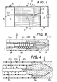
- Fig. 1 is an explanatory sectional view of a condenser in which this invention is preferably applied;
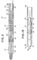
- Fig. 2 is an axial sectional view of an apparatus in accordance with this invention;
- Fig. 3 is a sectional view, in an axial direction, of another apparatus in accordance with this invention;
- Fig. 4 is an axial sectional view of still another apparatus in accordance with this invention;
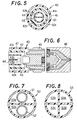
- Figs. 5 and 6 are respectively a cross sectional view of a supplying hose employed in further apparatus in accordance with this inventionand an exploded axial sectional view of the apparatus;
- Figs. 7 and 8 are respectively a - cross sectional view of a supplying hose employed in still further apparatus in accordance with this invention;
- Fig. 9 is an axial sectional view of an essential part of an embodiment of a spray coating apparatus, including a nozzle insert, of this invention;
- Figs. 10-12 are respectively a cross- sectional view taken along the section line III-III, IV-IV, and V-V in Fig. 9;
- Fig. 13 is an axial sectional view in elevation of a part of the nozzle insert in Fig. 9;
- Fig. 14 is a side view seen from right side of the nozzle insert in Fig. 13; and
- Fig. 15 is a schematic view showing how the inner surface of a condenser tube is coated with the apparatus in Fig. 9 of this invention.
- With reference to the appended drawings detailed description of the preferred embodiments will be made hereunder.
- A
surface condenser 10 employed in a thermal power plant (station), being connected with a steam-turbine, is shown in Fig. 1, wherein a large cylindrical fluid-tight,sealable condenser shell 1 is divided into three chambers with a pair ofcondenser tube plates plates condenser shell 1 outside thetube plates condenser water boxes - On top of the condenser shell 1 (hereinafter simply called shell) a
steam inlet 11 is disposed centrally located for receiving the exhaust steam from the steam turbine; on the lower side of the shell 1 a condensed water recovering (receiving)inlet 12 is made, similarly centrally located in the alteral direction, as can be seen in Fig. 1. In thecondenser water box 6 on the left side of Fig. 1 a coolingwater outlet 16 is provided on top of theshell 1; in the right side of the water box 7 a coolingwater inlet 17 is provided on the lower side of theshell 1. Avent 13 is formed on one flank of theshell 1. The coolingwater inlet 17 and the coolingwater outlet 16 are respectively connected to a circulating water pump; the condensedwater receiving inlet 12 is connected to a condensate pump; and thevent 13 is connected to an exhaust pump. These pumps are however not shown in the drawings. In short, the cooling water in acondenser 10 of this type is flowed through the condenser tubes 4 from right to left in Fig. 1, while the exhaust steam from the steam turbine is passed through the gap left among the condenser tubes 4 almost downwardly on the other hand, so as to perform a heat transference between the cooling water and the exhaust steam through the contact of both at the wall of the condenser tubes with a result of condensing the exhaust steam into water. - In making anti-corrosion coating of the whole length of the interior of such condenser tubes 4 in the
condenser 10, a coating operator enters into one, or both when it is necessary, of thecondenser water boxes condenser 10 for operating the spray nozzle there. Assuming a concrete example where the operator works in thewater box 6, he inserts a supplyinghose 22 having aspray nozzle 21 on the tip thereof and respective passages for paint and compressed air into one side opening of a condenser tube 4 and continues to push it deeper therein until thespray nozzle 21 reaches, passing through the whole length (5-40 m) of it, the other end opening of the condenser tube 4 on the side of thewater box 7. When thespray nozzle 21 has reached the destination, the supplyinghose 22 begins to be drawn back with a mechanical means at a predetermined speed, upon starting the spraying of the paint. The paint to be sprayed and the compressed air are supplied from a paint reservoir (not shown) and an air transformer (not shown) respectively situated in thewater box 6 or outside thecondenser 10, through the separate passages. The paint is atomized for being sprayed at thenozzle 21 with the aid of the compressed air in a well known way. With the starting of spraying paint thenozzle 21 is pulled back by the earlier stated mechanical means steadily from thewater box 7 toward thewater box 6 while continuing the coating operation regularly throughout the whole length of the condenser tube 4. Upon completely pulling back the supplyinghose 22 to the starting place spraying of the paint is ceased by the stoppage of supplying the paint and the compressed air. At the finish of painting of a first condenser tube 4 similar operation begins with a second condenser tube 4, and then with a third. The protective coating of the lots of condenser tubes 4 is continued in the same method until all of them in thecondenser 10 are coated. - Such a coating process which is susceptible to various environmental conditions, such as temperature, humidity, etc., requires to be maintained at an optimum situation for forming a non-defective and uniform thick film. The present invention is aimed at obtaining an optimum spraying conditoin of the paint through nebulization or atomization of the paint at the
spray nozzle 21 by means of supplying the paint and the compressed air, through the respective passage in the supplyinghose 22, heated at a most preferable temperature for coating such as 15-35°C. - As a method for heating the paint or the compressed air in the supplying
hose 22 according to this invention there are variety of effective ones available such as directly heating them by an electric heating means, for example, an electrical heating wire; cycling a heating medium in the supplyinghose 22, or combination of those means, etc. - What is illustrated in Fig. 2 is an example of electrical heating means, being effective in realizing this invention and extremely simple in structure, wherein a front end portion of a nozzle is shown as an axial sectional view. The paint and the compressed air delivered thereto are heated there up to a predetermined temperature in a very short time.
- According to Fig. 2, a
spray nozzle 21 of ordinary structure is provided with apaint passage 21 a in the central part and anair passage 21 b embracing the former completely in it for spraying the paint by the action of the compressed air in atomization state. The supplyinghose 22 to which thenozzle 21 is attached is composed of aflexible hose 23 of double-structure leading the paint and the compressed air from outside the condenser tube 4 and ametallic heating pipe 24 of a predetermined length for heating the paint and the compressed air delivered thereto by theflexible hose 23. - The
flexible hose 23 is constituted of aninside tube 23a made of polyvinyl chloride or the like for forming a paint route or passage and a flexibleoutside tube 23b made of hard plastic for example hard nylon or metallic flexible tube being concentric with theinside tube 23a to form an air route or passage therebetween. Theheating pipe 24 which is attached with a joint. 25 to the tip of theflexible hose 23, just like the latter, of double structure consisting of aninside pipe 24a and anoutside pipe 24b. Theinside pipe 24a is communicated with theinside tube 23a for forming a paint passage and theoutside pipe 24b is communicated with theoutside tube 23b for forming an air passage. Around the external surface of theinside pipe 24a a sheathedheater 26, for example sheath element 0.2-1 mm¢· and external diameter of the sheath 1.6-4.8 mmo, as an electric heating means is wound like a coil for heating directly the compressed air and indirectly, via a pipe wall of theinside pipe 24a, the paint under the control of athermostat 27 attached to the tip of the sheathedheater 26. Power supply to the sheathedheater 26 is executed by alead wire 28 extending through theoutside tube 23b so far as to get out of the condenser tube 4; and the sheathedheater 26 is covered by a stainless-steel-made tube for being completely separated from theinside pipe 24a for feeding the paint, so there is no likelihood and no danger of a fire or an explosion. The above- mentionedheating pipe 24 is, at the tip thereof, connected to thenozzle 21 by way of a joint 29; theinside pipe 24a is connected to apaint passage 21 a of thenozzle 21 and theoutside pipe 24b is connected to anair passage 21 b of thenozzle 21. - With such a structure, the paint and the compressed air delivered from outside the condenser tube 4 through the
flexible hose 23 are respectively heated to a predetermined temperature by the sheathedheater 26 at theheating pipe 24 for being immediately led to thenozzle 21, where the heated paint is sprayed in atomization by the action of the similarly heated compressed air. Incidentally, for heating the paint and the compressed air from 5°C to 30°C respectively, under conditions where the compressed air gushing (blowing) amount is 300 I/min. and the paint discharged amount is 100 ml/min and theheater 26 has a length of 360 mm., it has to be maintained at 150°C under the control of thethermostat 27. The length of the heating portion with the sheathedheater 26, i.e., the length of theheating pipe 24 may be suitably determined depending upon the compressed air amount, the paint discharge amount, the material quality of the heater's inserting portion, the heating condition, etc., with a variety of choice, for example, from ordinary length of approx. 300 mm to an extremely long case of covering the whole length of the supplyinghose 22. In a case wherein the paint and the compressed air are heated ranging the whole length of the supplyinghose 22, the same pipe is preferable to be flexible over the whole length from the view point of easiness of its handling, and required to be made of a material sufficiently resistant to a temperatue of 40-60°C. It is effective to employ a heat-resistant plastic for both the inside tube and the outside tube of the supplyinghose 22 or employ a metallic flexible tube for the outside tube. - In Fig. 3 another embodiment of this invention, wherein the similar sheathed heater to that in Fig. 2 is employed, is shown. A
spray nozzle 31 is connected therein by way of a joint 30 to aflexible hose 23 as the supplyinghose 22. On one end of the joint 30 anozzle insert 31 a with a paint passage in the central part is coaxially threaded, and anozzle cap 31b is threaded on the external side of the joint 30. A gap formed between thenozzle insert 31 a and thenozzle cap 31 b constitutes a passage for the compressed air. On the other end of the joint 30 theoutside tube 23b, which delivers the compressed air in theflexible hose 23 of double structure, is firmly fitted; and at the same time on a metallicinner tube 30a, which is fitted into a central through-bore of the joint 30, theinside tube 23a for feeding the paint is firmly fitted. On the external surface of the metallicinner tube 30a fitted into the joint 30 a sheathedheater 32 is wound about for heating the paint and the compressed air by being supplied with power through alead wire 28 running along theoutside tube 23b, just like in the previous embodiment. As the length of the heating portion in the structure of this embodiment coincides with that of theinner tube 30a wound by the sheathedheater 32, which facilitates the adjustment of the length thereof relatively easily. Theoutside tube 23b of theflexible hose 23 can be utilized, as it is, as an outside tube to theinner tube 30a, advantageously eliminating the putting of a separate metallic pipe as in Fig. 2. - Still another embodiment with an electrical heating means such as a sheathed heater is shown in Fig. 4, wherein a
flexible hose 23 as the supplyinghose 22 is, unlike the previous ones, of triple structure. Between aninside tube 23a and anoutside tube 23b amedian tube 23c is coaxially disposed. On the external surface of theinside tube 23a a sheathedheater 33 is wound about, while a gap formed between theinside tube 23a and the median tube 23C is filled with a suitable heat conducting medium such as air, water, etc., which functions along with a sheathedheater 33 to heat the paint fed through theinside tube 23a and the compressed air fed through theoutside tube 23b respectively _to a predetermined temper- atu re. - In such a structure, the paint and the compresed air in the
flexible tube 23 are maintained at a suitable temperature, even when the coating operation is temporarily suspended and the heating with the sheathedheater 33 is stopped by any chance, by the heat kept in the heat conducting medium. The paint and the compressed air are advantageously protected from being affected by the ambient conditions immediately. This structure is particularly useful in a system wherein the heating means is disposed ranging the whole length of the supplyinghose 22. - Several embodiments described above all relate to systems in which an electrical heating means is adopted; this invention is however applicable to another type of apparatus wherein heated fluid is cycled in the supplying hose.
- In an embodiment shown in Figs. 5 and 6 a
flexible hose 40, which extends from outside of the condenser tube 4 to a predetermined position in the condenser tube 4, is constituted of anoutside tube 41 of hard plastic for forming acompressed air passage 41 a, amedian tube 42 for forming apaint passage 42a, and aninside tube 43 of heat-resistant plastic for forming a passage (forward and backward) for heated fluid. Three of these are all coaxially arranged to make a triple structure. And in theinside tube 43 a long partition is disposed in a diametric direction ranging the whole length of the tube to divide the inside into two parts, i.e., forward flowingpassage 43a and a backward flowingpassage 43b. To the end portion of the flexible hose 40 aspray nozzle 46 is attached by way of a suitable joint 45. Theinside tube 43 is not blocked by the joint 45, but theforward flowing passage 43a and the backward flowingpassage 43b thereof are communicated to each other only in the end portion, that is, in the attaching portion of thespray nozzle 46. Accordingly, warm and heated water from a water supplying tank similarly disposed as the paint reservoir outside the condenser tube, or heated air (or other heated fluid) from a suitable heating means comes through theinside tube 43, specifically through theforward flowing passage 43a, to the vicinity of the attaching portion of thespray nozzle 46, where it is flowed back through the backward flowingpassage 43b to outside of the condenser tube 4. In the cycling course of such a flowing forward and backward of the heating medium through theforward flowing passage 43a and the backward flowingpassage 43b, the paint and the compressed air flowed through the respective passage (41 a, 42a) are heated by the heating medium up to a predetermined temperature. - When such a cycling system of a heating medium is adopted, the amount of the medium used in the cylcing is, in contrast to the amount of the medium in a direct heating type hot air system, small and economical because of a possible small size of the heater capacity, outside the condenser tube 4.
- If a metallic heating tube of small length, like one in Fig. 2 designated with 24, is attached in the above embodiment to a portion adjacent to the
nozzle 46, the paint and the compressed air will be further stabilized in their required temperature. - The same object can be attained by incorporating a sheath heater in the
inside tube 43 and by cycling only the air therethrough. - Another example of heating by means of heated fluid can be seen in Fig. 7 or Fig. 8, either being effective.
- In a half-splittable type
flexible hose 50 of hard plastic, shown in Fig. 7, a pair of smalldiametered tubes sections flexible hose 50. Either one, for example, 51 is adapted to pass the paint and the other may be adapted for passing the compresed air; and one section 50a. is used as a forward flowing passage for the heating medium and theother section 50b as a backward fluid passage of the same. In this embodiment sheathed heaters may be wound about each of thesmall diametered tubes hose 53 is divided into four sections, one pair of diagonally positionedsections sections - Those supplying
hoses - Further, a spray gun preferably employable in the present invention, shown in Figs. 9-14, is provided with a cylindrical
outer casing 61, which is on either male-screwed end portions thereof threaded by acenter guide - On one end of the
outer casing 61 anozzle cap 64 is concentrically fastened thereto at aflange 64a thereof by thecenter guide 62. - An
inner casing 65 having an external diameter smaller than the internal diameter of theouter casing 61 by a predetermined amount is disposed inside, and concentrically with, theouter casing 61. To the right end, in Fig. 9, of the inner casing 65 anozzle insert 68 having a throughbore 68a in the axis thereof is threaded into. A sheathed heater, as not shown, such as that illustrated in Fig. 2 is wound about on the external surface of theinner casing 65. Thenozzle insert 68 is provided with ahexagonal prism portion 68b which is inscribable in a hollowcylindrical portion 64b of thenozzle cap 64 and aconical portion 68c faced to a hollowconical space 64c of thenozzle cap 64 with a predetermined gap. Between the inner surface of the hollowcylindrical portion 64b and each of six flat sides of thehexagonal prism portion 68b six straight but arch ceiling shapedspaces 69 are left lengthwise as seen in Fig. 12; on the surface of thenozzle insert 68 aspiral groove 70 is inscribed with a certain angle a to the axis thereof, as can be seen in Figs. 13 and 14. It signifies therefore that two kinds of flow passages for the blowing or atomizing gas, for example compressed air, are formed between thenozzle cap 64 and thenozzle insert 68, i.e., the six straightly elongated spaces 69 (which will be called straight grooves) and threespiral grooves 70. - The left end (in Fig. 9) of the
inner casing 65 is threaded in aboss 61 a of theouter casing 61 as to leave apredetermined space 71 between theinner casing 65 and theouter casing 61. Through a suitable number of through-holes 61 b formed in theboss 61 a and thespace 71, a passage for the atomizing (spraying) gas is amde in the direction toward thenozzle cap 64. The atomizing gas is supplied by anair hose 76 attached to the open end of thecenter guide 63; theair hose 76 is usually made into adouble hose 75, i.e. a supplying hose, containing apaint supply passage 66 therein, for being inserted deep into, and drawn back out of a tube to be coated. Theboss 61 a is provided with a fitting 67 threaded thereinto, to the other end thereof thepaint supply passage 66 is intended to be connected. The fitting 67, theinner casing 65, and the through-bore 68a in thenozzle insert 68 constitute a route for supplying the paint. - In the spray gun of such a structure the paint is supplied through an inside route of a double tube formed by the
center guide 63 and the fitting 67, and atomizing gas led by theair hose 76 is supplied through an outside route of the double tube. The paint coming through the fitting 67, theinner casing 65, and the through-bore 68a of thenozzle insert 68 is sprayed out of atip portion 73 of the through-bore 68a; and the blowing gas such as compressed air is led forward through the through-holes 61 b and thespace 71, and is further given a straight going force in thestraight grooves 69 and a spirally advancing force through thespiral groove 70, before it is blown, getting through the space between theconical portion 68c of thenozzle insert 68 and the hollowconical space 64c of thenozzle cap 64, out of agas blowing portion 72. This blowing (or spraying) gas atomizes the paint gushing out of thetip portion 73 of the through-bore 68a of thenozzle insert 68, while spiraling the same, which enables the paint to be sprayed uniformly toward the inner surface of the tube-to-be-coated. By means of shifting backwards the spray gun itself of this type, once inserted deep through to the other end opening of the tube to be coated, at a constant speed, while spraying the paint in atomization, along the inside of that tube (leftward direction in Fig. 9), a method of coating the inner surface of a long tube of small diameter throughout the entire length thereof has just been established. - Describing more specifically, for coating the inner surface of a
long condenser tube 81 of small diameter, as shown in Fig. 15, adouble hose 75, having aspray nozzle 80 of this invention on the tip thereof, is inserted into thecondenser tube 81 from one end opening 81 a thereof as far as the other end opening 81 b throughout the whole length (5-40 m) of thecondenser tube 81. The moment when thespray nozzle 80 has reached the other end opening 81 b of thecondenser tube 81 spraying of the paint is commenced with atomization. The paint and the atomizing gas are independently supplied through their respective passage, as mentioned above, before reaching thespray nozzle 80, where the former is sprayed in atomization due to the double directional spraying force of the latter, i.e., straight and spiral. As soon as the spraying of the paint is commenced, thedouble hose 75 is drawn back while spraying the paint from thespray nozzle 80, by means of a suitable mechanical means, at a predetermined constant speed from the other end opening 81 b toward the one end opening 81 a of thecondenser tube 81. During this shifting or movement of thespray nozzle 80, due to the drawing back of thedouble hose 75 through thecondenser tube 81, the inner surface thereof is gradually and regularly coated with the atomized paint. The whole length of thecondenser tube 81 can thus be coated with a uniform thickness from one end to the other end thereof. When thespray nozzle 80 has returned to the one end opening 81 a, the supplying of the paint and the atomizing gas is suspended to stop the coating operation. When onecondenser tube 81 is finished coating in this way another and a third tube will be coated in order successively in a similar way. By this continuous and repeated protective coating operation, a condenser having a large number of condenser tubes can be coated or re-coated on the inner surface thereof quite smoothly and effectively. - The shape of the spiral groove or
grooves 70 formed (inscribed) on the external surface of thenozzle insert 68 may be varied according to the internal diameter of thecondenser tube 81 to be coated. It is appropriate in normal cases to determine the twist angle α formed between thespiral groove 70 and the axis of the nozzle insert 68 (see Fig. 13) in the range of 15-60°. And it is preferable to set the spray angle 0, that is a half of the vertical angle of theconical portion 68c of thenozzle insert 68, within the range of 5-45° so as to ensure the best spraying condition at a place 200 mm distant from the tip of thespray nozzle 80. - In the above embodiment the
nozzle insert 68 is provided with thehexagonal prism portion 68b which is easy in machining, but the shape of this prism portion is by no means limited to the hexagon. It is of course variable in various suitable ways to those skilled in the art, for example, quadrangular or octangular prism and so on, without any difficulty. - This invention is by no means limited to the abovementioned methods and apparatuses, but it can be varied and modified in many ways within the spirit of this invention by those skilled in the art. As to the paint to be used in this invention, variety of ones suitable to the coating of long tubes of small diameter can be numerated; among those some organic synthetic resin coatings or paints, which may be cured at a room temperature or its neighborhood, are preferable for the purpose of anti- corrosion coating. As their base or vehicle alkyd resin, vinyl chloride resin, polyurethane resin, epoxy resin, silicone resin, acrylic resin, etc., are exemplified.
- Before concluding the description an experiment for clarifying the effect of this invention will be disclosed hereunder.
- In a condenser provided with 6200 condenser tubes of copper alloy (JIS H 3300), whose dimension was 25.4 mm in external diameter, 22.9 mm in internal diameter, and 15330 mm in length, a protective coating method was applied to 1500 condenser tubes out of all.
- First of all the condenser tubes to be coated were repeatedly cleansed fifty times by sponge balls with silicon carbide grains stuck thereon, followed by water cleansing, draining and drying.
- After the above-mentioned cleansing the tubes were coated by the apparatus shown in Fig. 2 for protecting from corrosion. It was carried out under rather severe condition to the eyes of those skilled in the art particularly:
- temperature: 5-10°C
- humidity: 60%
- The paint used was:
- kind: zinc chromate primer
- viscosity: 20 sec. by No. 4 Ford viscosity cup (15°C)
- The coating conditions were:
- amount of the paint discharged: 60 ml/min.
- amount of the air supplied: 300 I/min. shifting velocity of the nozzle: 500 mm/sec.
- The drying condition:
- the wind velocity: 2.5 m/sec., 24 hours After the anti-corrosion coating, the result was examined in all of the 1500 condenser tubes. A part of the tube end 1.5 m from the end opening was visually examined with a tube examined scope. On the side from where the wind gets out, some flowing downward or gathering of the paint was found within 1 meter range from the end opening in only ten tubes out of the 1500 tubes.
- The result may be said surprisingly excellent considering the severe conditions under which the coating was carried out.
- In a measuring test of the thickness of the coated film on the lower side of the tube at a position 500 mm from the end opening executed with a film-thickness meter of eddy current type, the results were so good as 18.5,u in an average thickness and 2.5 µ in a standard deviation.
Claims (11)
Applications Claiming Priority (4)
| Application Number | Priority Date | Filing Date | Title |
|---|---|---|---|
| JP147890/79 | 1979-10-25 | ||
| JP1979147890U JPS6110775Y2 (en) | 1979-10-25 | 1979-10-25 | |
| JP63681/80 | 1980-05-14 | ||
| JP6368180A JPS56161870A (en) | 1980-05-14 | 1980-05-14 | Method and apparatus for coating long pipe having small diameter |
Publications (2)
| Publication Number | Publication Date |
|---|---|
| EP0028088A1 EP0028088A1 (en) | 1981-05-06 |
| EP0028088B1 true EP0028088B1 (en) | 1984-02-08 |
Family
ID=26404816
Family Applications (1)
| Application Number | Title | Priority Date | Filing Date |
|---|---|---|---|
| EP19800303602 Expired EP0028088B1 (en) | 1979-10-25 | 1980-10-13 | Method, apparatus and spray nozzle for coating the inner surface of long tubes of small diameter |
Country Status (2)
| Country | Link |
|---|---|
| EP (1) | EP0028088B1 (en) |
| DE (1) | DE3066513D1 (en) |
Cited By (2)
| Publication number | Priority date | Publication date | Assignee | Title |
|---|---|---|---|---|
| WO2022152765A1 (en) * | 2021-01-12 | 2022-07-21 | Säkaphen Gmbh | System for spraying a coating agent onto pipe inner walls, and spraying apparatus for this system |
| EP4501462A4 (en) * | 2022-03-31 | 2025-02-05 | Musashi Engineering, Inc. | Atomization nozzle, atomization device, spraying device, and atomization method |
Families Citing this family (13)
| Publication number | Priority date | Publication date | Assignee | Title |
|---|---|---|---|---|
| US4368219A (en) * | 1980-06-13 | 1983-01-11 | Sumitomo Light Metal Industries Ltd. | Method and apparatus for coating the inner surface of long tubes of small diameter |
| GB2145014A (en) * | 1983-08-12 | 1985-03-20 | Anthony Joseph Torntore | Material spraying apparatus |
| BE1000767A7 (en) * | 1987-07-16 | 1989-03-28 | Recticel | METHOD AND APPARATUS FOR FORMING A layer of polyurethane on a surface by spraying. |
| DE3800448A1 (en) * | 1988-01-09 | 1989-07-20 | Ribnitz Peter | METHOD AND DEVICE FOR THE CONTINUOUS COATING OF WORKPIECES |
| FR2715084B1 (en) * | 1994-01-14 | 1996-04-05 | Ryser Sarl Ets Ernest | Method and device for applying a coating in a buried pipeline. |
| US6334579B1 (en) * | 1999-02-18 | 2002-01-01 | Honeywell Measurex Devron Inc. | Air atomizing nozzle |
| JP2005188666A (en) * | 2003-12-26 | 2005-07-14 | Toray Eng Co Ltd | Pipe and system for liquid conveyance |
| DE102007017768B4 (en) * | 2007-04-16 | 2010-02-11 | Innovaris Gmbh & Co. Kg | Hot gas generator for a thermal spraying machine |
| CN103316792B (en) * | 2013-06-26 | 2016-03-02 | 电子科技大学 | Prepare the gas phase spray equipment of organic nano line and the preparation method of Alq3 nano wire |
| EP3205407B1 (en) * | 2016-02-09 | 2019-09-25 | IPR-Intelligente Peripherien für Roboter GmbH | Method and installation for covering internal walls of a cavity with a protective layer made of corrosion protecting wax |
| CN113578616A (en) * | 2021-08-25 | 2021-11-02 | 重庆忠泽科技有限公司 | Composite steel pipe lining spraying device and composite steel pipe |
| CN115178410B (en) * | 2022-08-24 | 2023-07-18 | 赣州市桐鑫金属制品有限公司 | Outer wall paint spraying machine for metal fence production |
| CN115301431B (en) * | 2022-09-14 | 2023-08-15 | 华能国际电力股份有限公司 | High-viscosity slurry atomizing nozzle for inner wall of boiler tube of thermal power unit |
Family Cites Families (6)
| Publication number | Priority date | Publication date | Assignee | Title |
|---|---|---|---|---|
| DE466932C (en) * | 1928-11-06 | Joh Weinlich | Nozzle for paint atomizer | |
| US2314329A (en) * | 1938-03-12 | 1943-03-23 | Walter M Ericson | Art of spraying coatings, particularly asphaltic coatings and the like |
| US2520397A (en) * | 1946-12-05 | 1950-08-29 | Marion C Green | Spraying apparatus for internally coating pipes |
| US2576942A (en) * | 1948-07-06 | 1951-12-04 | American Can Co | Apparatus for the continuous spraying of individual container bodies |
| US2984421A (en) * | 1958-08-11 | 1961-05-16 | Sarah A Hession | Adjustable aerosol device |
| FR88147E (en) * | 1963-12-14 | 1966-12-16 | Device for heating a fluid stream |
-
1980
- 1980-10-13 DE DE8080303602T patent/DE3066513D1/en not_active Expired
- 1980-10-13 EP EP19800303602 patent/EP0028088B1/en not_active Expired
Cited By (2)
| Publication number | Priority date | Publication date | Assignee | Title |
|---|---|---|---|---|
| WO2022152765A1 (en) * | 2021-01-12 | 2022-07-21 | Säkaphen Gmbh | System for spraying a coating agent onto pipe inner walls, and spraying apparatus for this system |
| EP4501462A4 (en) * | 2022-03-31 | 2025-02-05 | Musashi Engineering, Inc. | Atomization nozzle, atomization device, spraying device, and atomization method |
Also Published As
| Publication number | Publication date |
|---|---|
| EP0028088A1 (en) | 1981-05-06 |
| DE3066513D1 (en) | 1984-03-15 |
Similar Documents
| Publication | Publication Date | Title |
|---|---|---|
| US4370944A (en) | Apparatus for coating the inner surface of long tubes of small diameter | |
| EP0028088A1 (en) | Method, apparatus and spray nozzle for coating the inner surface of long tubes of small diameter | |
| US4335677A (en) | Coating of the inner surface of tubes | |
| US4368219A (en) | Method and apparatus for coating the inner surface of long tubes of small diameter | |
| KR840000611B1 (en) | Coating composition for protecting inner surface of tubes in heat-exchangers | |
| US3106491A (en) | Pipe cleaning and coating apparatus | |
| US4210507A (en) | Electrocoating flow control electrode and method | |
| DE102010015497A1 (en) | Externally mixing multi-fluid nozzle for minimal internal heat transfer | |
| US2267264A (en) | Air conduit heater | |
| JPS6357081B2 (en) | ||
| US2481813A (en) | Spray painting apparatus | |
| RU2179076C2 (en) | Method of and device for applying corrosion-resisting coating on internal surface of pipeline | |
| EP0456752A1 (en) | Vortex tube used to supply lphv air to spray apparatus | |
| US7836844B2 (en) | Method for protecting against corrosion and scale deposit and for restoring tubes of heat-exchanging equipment and device for carrying out said method | |
| KR840002228B1 (en) | Coating device on inner surface of heat transfer pipe in condenser | |
| US11235347B2 (en) | System and method for coating tubes | |
| JP4695090B2 (en) | Exhaust conduit for rotary atomizer with pneumatic turbine | |
| JP3353513B2 (en) | Painting gun and painting method | |
| JPH08224541A (en) | Method for producing colored coated zinc-aluminum alloy plated wire | |
| KR840002239B1 (en) | Method for coating the inner surface of long tuber of small diameter | |
| US1981130A (en) | Method of and apparatus for coating strands | |
| KR840001288Y1 (en) | Tube shaving device | |
| IT202000000761U1 (en) | HEAD FOR PAINT GUN | |
| JPH03133632A (en) | Heat transfer pipe for u-shape type heat exchanger and manufacture therefor | |
| CN214423906U (en) | Building coating paints device |
Legal Events
| Date | Code | Title | Description |
|---|---|---|---|
| PUAI | Public reference made under article 153(3) epc to a published international application that has entered the european phase |
Free format text: ORIGINAL CODE: 0009012 |
|
| AK | Designated contracting states |
Designated state(s): BE DE FR GB IT NL SE |
|
| 17P | Request for examination filed |
Effective date: 19810509 |
|
| ITF | It: translation for a ep patent filed | ||
| GRAA | (expected) grant |
Free format text: ORIGINAL CODE: 0009210 |
|
| AK | Designated contracting states |
Designated state(s): BE DE FR GB IT NL SE |
|
| REF | Corresponds to: |
Ref document number: 3066513 Country of ref document: DE Date of ref document: 19840315 |
|
| ET | Fr: translation filed | ||
| PLBE | No opposition filed within time limit |
Free format text: ORIGINAL CODE: 0009261 |
|
| STAA | Information on the status of an ep patent application or granted ep patent |
Free format text: STATUS: NO OPPOSITION FILED WITHIN TIME LIMIT |
|
| 26N | No opposition filed | ||
| PGFP | Annual fee paid to national office [announced via postgrant information from national office to epo] |
Ref country code: SE Payment date: 19890828 Year of fee payment: 10 |
|
| PGFP | Annual fee paid to national office [announced via postgrant information from national office to epo] |
Ref country code: GB Payment date: 19890831 Year of fee payment: 10 |
|
| PGFP | Annual fee paid to national office [announced via postgrant information from national office to epo] |
Ref country code: FR Payment date: 19890925 Year of fee payment: 10 |
|
| PGFP | Annual fee paid to national office [announced via postgrant information from national office to epo] |
Ref country code: BE Payment date: 19891011 Year of fee payment: 10 |
|
| PGFP | Annual fee paid to national office [announced via postgrant information from national office to epo] |
Ref country code: DE Payment date: 19891012 Year of fee payment: 10 |
|
| ITTA | It: last paid annual fee | ||
| PGFP | Annual fee paid to national office [announced via postgrant information from national office to epo] |
Ref country code: NL Payment date: 19891031 Year of fee payment: 10 |
|
| PG25 | Lapsed in a contracting state [announced via postgrant information from national office to epo] |
Ref country code: GB Effective date: 19901013 |
|
| PG25 | Lapsed in a contracting state [announced via postgrant information from national office to epo] |
Ref country code: SE Effective date: 19901014 |
|
| PG25 | Lapsed in a contracting state [announced via postgrant information from national office to epo] |
Ref country code: BE Effective date: 19901031 |
|
| BERE | Be: lapsed |
Owner name: SUMITOMO LIGHT METAL INDUSTRIES LTD Effective date: 19901031 |
|
| PG25 | Lapsed in a contracting state [announced via postgrant information from national office to epo] |
Ref country code: NL Effective date: 19910501 |
|
| GBPC | Gb: european patent ceased through non-payment of renewal fee | ||
| NLV4 | Nl: lapsed or anulled due to non-payment of the annual fee | ||
| PG25 | Lapsed in a contracting state [announced via postgrant information from national office to epo] |
Ref country code: FR Effective date: 19910628 |
|
| PG25 | Lapsed in a contracting state [announced via postgrant information from national office to epo] |
Ref country code: DE Effective date: 19910702 |
|
| REG | Reference to a national code |
Ref country code: FR Ref legal event code: ST |
|
| EUG | Se: european patent has lapsed |
Ref document number: 80303602.9 Effective date: 19910507 |