EP0028046B1 - Hot water boiler - Google Patents
Hot water boiler Download PDFInfo
- Publication number
- EP0028046B1 EP0028046B1 EP80200998A EP80200998A EP0028046B1 EP 0028046 B1 EP0028046 B1 EP 0028046B1 EP 80200998 A EP80200998 A EP 80200998A EP 80200998 A EP80200998 A EP 80200998A EP 0028046 B1 EP0028046 B1 EP 0028046B1
- Authority
- EP
- European Patent Office
- Prior art keywords
- castings
- passages
- sump
- water
- boiler
- Prior art date
- Legal status (The legal status is an assumption and is not a legal conclusion. Google has not performed a legal analysis and makes no representation as to the accuracy of the status listed.)
- Expired
Links
Images

Classifications
-
- F—MECHANICAL ENGINEERING; LIGHTING; HEATING; WEAPONS; BLASTING
- F24—HEATING; RANGES; VENTILATING
- F24H—FLUID HEATERS, e.g. WATER OR AIR HEATERS, HAVING HEAT-GENERATING MEANS, e.g. HEAT PUMPS, IN GENERAL
- F24H8/00—Fluid heaters characterised by means for extracting latent heat from flue gases by means of condensation
-
- F—MECHANICAL ENGINEERING; LIGHTING; HEATING; WEAPONS; BLASTING
- F24—HEATING; RANGES; VENTILATING
- F24H—FLUID HEATERS, e.g. WATER OR AIR HEATERS, HAVING HEAT-GENERATING MEANS, e.g. HEAT PUMPS, IN GENERAL
- F24H1/00—Water heaters, e.g. boilers, continuous-flow heaters or water-storage heaters
- F24H1/22—Water heaters other than continuous-flow or water-storage heaters, e.g. water heaters for central heating
- F24H1/24—Water heaters other than continuous-flow or water-storage heaters, e.g. water heaters for central heating with water mantle surrounding the combustion chamber or chambers
- F24H1/26—Water heaters other than continuous-flow or water-storage heaters, e.g. water heaters for central heating with water mantle surrounding the combustion chamber or chambers the water mantle forming an integral body
- F24H1/28—Water heaters other than continuous-flow or water-storage heaters, e.g. water heaters for central heating with water mantle surrounding the combustion chamber or chambers the water mantle forming an integral body including one or more furnace or fire tubes
-
- F—MECHANICAL ENGINEERING; LIGHTING; HEATING; WEAPONS; BLASTING
- F24—HEATING; RANGES; VENTILATING
- F24H—FLUID HEATERS, e.g. WATER OR AIR HEATERS, HAVING HEAT-GENERATING MEANS, e.g. HEAT PUMPS, IN GENERAL
- F24H1/00—Water heaters, e.g. boilers, continuous-flow heaters or water-storage heaters
- F24H1/22—Water heaters other than continuous-flow or water-storage heaters, e.g. water heaters for central heating
- F24H1/24—Water heaters other than continuous-flow or water-storage heaters, e.g. water heaters for central heating with water mantle surrounding the combustion chamber or chambers
- F24H1/30—Water heaters other than continuous-flow or water-storage heaters, e.g. water heaters for central heating with water mantle surrounding the combustion chamber or chambers the water mantle being built up from sections
- F24H1/32—Water heaters other than continuous-flow or water-storage heaters, e.g. water heaters for central heating with water mantle surrounding the combustion chamber or chambers the water mantle being built up from sections with vertical sections arranged side by side
-
- Y—GENERAL TAGGING OF NEW TECHNOLOGICAL DEVELOPMENTS; GENERAL TAGGING OF CROSS-SECTIONAL TECHNOLOGIES SPANNING OVER SEVERAL SECTIONS OF THE IPC; TECHNICAL SUBJECTS COVERED BY FORMER USPC CROSS-REFERENCE ART COLLECTIONS [XRACs] AND DIGESTS
- Y02—TECHNOLOGIES OR APPLICATIONS FOR MITIGATION OR ADAPTATION AGAINST CLIMATE CHANGE
- Y02B—CLIMATE CHANGE MITIGATION TECHNOLOGIES RELATED TO BUILDINGS, e.g. HOUSING, HOUSE APPLIANCES OR RELATED END-USER APPLICATIONS
- Y02B30/00—Energy efficient heating, ventilation or air conditioning [HVAC]
Abstract
Description
- The invention relates to a hot water boiler especially though not exclusively a central heating boiler.
- Having regard to the rise in the cost of energy there has in recent years been a strongly felt need for designs of hot water appliances which provide a higher thermal yield in the water. A customary method for expressing the thermal yield of gas-fired boilers is based on the higher calorific value of the fuel i.e. on the calorific value of the fuel including latent heat. With conventional designs for hot water boilers, it is no simple matter to achieve a thermal yield in the water defined in this way exceeding 80%.
- Attempts have been made to improve the thermal yield by improved heat exchange between the fumes or burned gases and the water. DE-A-2 308 374 and EP-A-5 876 (falling under Article 54(3) of the E.P.C.) describe a boiler having two juxtaposed hollow castings containing passages for water and joined together to form an assembly enclosing a combustion chamber and, above it, a burned gas flue. The flue is connected to two passages for the burned gases which extend downwards on either side of the castings, with ribs being cast at either side of the castings projecting into the downward passages.
- The object of this invention is therefore to provide a design giving a higher thermal yield. The aim is a yield of over 90% or even 94%. At the same time a simple construction is sought, particularly one comprising fewer heat- exchanging surfaces.
- The invention as claimed seeks to provide a solution. Briefly, the castings enclosing the combustion chamber are located above a sump into which the burned gas passages extending down outside the castings open. A blower for the burned gases extracts them from the sump. Provision is made for the removal of condensate from the burned gases from the sump. Although the blower can be fastened to one side of the sump, preferably it is located at the upper side of the sump, next to the castings.
- In this new design, the burned gases pass upwards once only and then downwards along the castings, so that simplicity in design is achieved. The boiler is also specially designed for a heat transfer to the castings with condensation of water in the burned gases, so that the gases can be cooled down practically to the initial temperature of the water. In particular, the mass, the material and the shape of the outside of the castings, with the ribs on them, are such that in normal operating circumstances and during both continuous and intermittent operation at least half the water vapour present in the flue gases is condensed on the outer wall of the castings and on the ribs located on them.
- The choice of, for example, aluminium as the material for the castings is particularly important in this case since the casting wall temperature then remains lower longer during repeated heatings in intermittent operation and condensation is therefore more prolonged.
- It should be noted that it is known, from the theory of heat transfer by combustion gases, that the transfer yield rises rapidly if the wall to be warmed is kept sufficiently cool for intensive condensation to take place against it. For this, the wall must usually be kept at a temperature of less than 55°C, and preferably at about 45°C.
- Central heating boilers are usually adjusted with the aid of a thermostat on the on/off principle. The boiler burns, e.g. for three minutes, and subsequently cuts out for e.g. seven minutes. An expert in the heat transfer field can in each case calculate how great the mass and what the shape of the castings should be for the above requirements for condensation operation to be met. The condensate formed is collected in the sump and can run off via a discharge pipe, e.g. via a syphon. The flue gases which thereafter still contain only a fraction of the original humidity are then drawn off upwards by the blower.
- So that condensation can occur as effectively as possible over the outer surface of the castings, it is important for the water passages in the castings and the ribs on them to be particularly adapted for this requirement. This may be achieved in the boiler of the invention if the water passages in the castings extend substantially straight and vertically in contrast to many known designs with an upward widening at the point where the combustion chamber becomes the burned gas flue above the chamber and if the ribs on the outside of the castings project further at the upper end of the castings than at the lower end. As a result of the latter feature, the downwardly extending passages narrow downwardly at the outer side of the castings, so that the condensable water vapour enters into closer contact with the wall.
- It is also important for as little heat as possible to flow away to the parts of the structure which do not pass this heat onto the water, and that none of the water in the burned gases should condense in the combustion chamber or in the flue above it. The burned gases should desirably fall to a temperature at which such condensation commences only when they turn to pass downwards. This may be achieved in a boiler of the invention if the castings at least at the top ends of the combustion chamber are provided with an insulated external cladding and the downwardly extending passages outside the castings are bonded on the outside by a thin-walled material, preferably one having poor thermal conductivity, which has insulating covering. An additional beneficial effect is obtained by a radiation screen round a burner in the combustion chamber, which screen is spaced from the castings and extends from one third to half the height of the castings within the combustion chamber. This radiation screen prevents too much heat being transferred from the flames to the un-cooled top surfaces and adjoining parts of the sides of the castings and also maintains the burned gases at a high temperature to well within the flue above the burner chamber. The effect of the radiation screen can be further improved by cooling it on the outside. This is possible by connecting the space between the castings and the radiation screen to the combustion air supply, so that the cold combustion air can circulate along the outside of the radiation screen. This has the additional advantage that the cold air stream can prevent the deposit of dirt from the burned gases against the wall of the castings directed towards the combustion chamber.
- Although the greater part of the water in the burned gases is preferably already condensed before the gases reach the sump, and although the condensate will mainly be collected in the sump or condensation tray, some after-condensation may still occur in the outlet from the sump as a result of the very low residual temperature of the flue gases. It is therefore recommended that the blower is connected to a draft interrupter in which a chimney pipe can be fitted, the draft interrupter including an annular condensation trough projecting inwardly into the flow of gases and having a drainage opening. The drainage opening may in turn connect up e.g. to a sump or can also be linked directly to a discharge via a syphon.
- Depending on the residual temperature of the flue gases in the discharge outlet, consideration can further be given, if necessary, to conducting the incoming combustion gas round the stack through a double jacket before conveying it to the combustion area.
- Effective operation of the boiler with a high yield may also be dependent on the water being able to flow unhindered through the castings in an upward direction, on it being uniformly distributed over the breadth of the castings. To this end, preferably the turns from the upward flue to the downward passages for the burned gases are through openings in the castings and these castings narrow at their top ends towards the centre of the boiler castings where the water passages in these top ends are connected to the water discharge openings.
- As has already been noted, it is important that the lower end of the castings be kept at a sufficiently low temperature for condensation to occur. This can be assisted if water supply openings at the lower ends of the castings are jet-type passages and are arranged so that the water is directed against the walls opposite to the walls of the combustion chamber.
- Although the condensation of the water from the flue gases is largely determined by the mass and shape of the external surfaces of the castings, it is still important for the film of condensate to be as thin as possible. If this film is too thick, it reduces the heat transfer to the castings and prevents further condensation. In order to keep the water film as thin as possible, steps should preferably be taken to convey the coridensate away along the castings effectively and rapidly. This also prevents the condensate formed from re-evaporating and taking heat away from the water within the castings when the gas burner is switched off. Rapid discharge can be achieved by shaping the ribs at the outside of the castings as vertical fins which are interrupted in a staggered manner, the lower surfaces of the fins sloping inwardly and downwardly towards the walls of the castings, the fins being laterally separated from each other by small runnels.
- A particular advantage of the new design, finally, is that it may consist of easily mountable parts. In order to achieve an effective seal between these parts it is conceivable for the contacting surfaces to be finished for tight fitting, but a cheaper design can be obtained by pulling the castings, the sump and the various covers close together by means of clamping means, e.g. bolt connections, a seal being achieved by means of tubes of a flexible, temperature-resistant material, such as silicone rubber, laid in shallow arooves.
- An embodiment of the invention will be described below by way of non-limitative example with reference to the accompanying drawings, in which:-
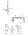
- Fig. 1 shows the preferred embodiment of the boiler of the invention in longitudinal vertical section,
- Fig. 2 shows a detail of the burned gas discharge in the boiler of Fig. 1,
- Fig. 3 shows a detail in section along the line III-III in Fig. 1,
- Fig. 4A shows a fin of the boiler of Fig. 1 on enlarged scale,
- Fig. 4B is a view on the line B-B in Fig. 4A,
- Fig. 4C is a view in the direction C in Fig. 4A.
- Fig. 1 shows two
hollow castings 1 containing passages for water and assembled together to provide the body of the boiler. Thecastings 1 are provided with surfaces in front and behind (as seen in Fig. 1) which fit together at their edges and by welding the surfaces along these edges a single structure is obtained. Top and bottom surfaces of the castings, as indicated in the drawing, are similarly connected to each other by welds. The castings are made of a light metal aluminium alloy.Ribs 6 are integrally cast on theexternal walls 2 of the castings. Although not shown in the drawings, ribs running horizontally can be cast within the water passages in castings, in order to obtain a labyrinthine path through the water passages. -
Openings 3 are provided in the rear walls of thecastings 1 at the lower ends connecting to tubes lying at the bottom of the water passages, from which jets of incoming are directed against theouter walls 2 of the castings, i.e. the walls opposite the walls of the combustion chamber. There areopenings 4 at the top of thecastings 1 to which discharge pipes for the heated water are in use connected. Fingers 5 are cast on the inside of the castings so as to project as fingers into a burned gas flue which extends upwardly from the combustion chamber. Anopening 7 is let into the front surface of the boiler through which combustion air can be sucked diagonally inwards, the gas being then conducted through an air distributor plate 8 to flow uniformly along agas burner 11. The burned gases resulting flow upwards through the burned gas flue. The transition from the combustion chamber to the flue is marked by a narrowing 12 in the gas passage and a corresponding upward widening in the water passages. Above this the gases impart some of their heat to the fingers 5 before passing from the inside of the castings to the outside through thegas ports 13. - Fig. 3 shows how the
gas ports 13 and thewater discharge 4 cross by each other. It also shows that the front and rear surfaces of the castings are provided on their outer side with a layer of insulatingmaterial 28 in order to prevent heat loss through these surfaces. The burned gases then flow downwards between theribs 6, closed passages being obtained by means of athin steel plate 14 which lies against theribs 6. Thissteel plate 14 is fastened tight against the castings. It is in turn provided on its outer side with a layer of insulatingmaterial 15, so that virtually no heat loss and heat transfer is possible between the flue gases and thesteel plate 14. The passages formed by theribs 6 narrows downwardly since the height (projection) of the ribs is gradually reduced. Since the water vapour in the burned gases condenses in these downward passages it is important for contact between the ribs and the flue gases to be as good as possible. This is achieved inter alia by the narrowing of these downward passages. - The
castings 1 are fitted closely to acast sump 16 which has a floor sloping down to a low point at which acondensate discharge opening 17 allows condensate collecting in the sump to be removed, for example to a drain. The downward passages for the burned gases open directly into the sump, which can thus act to collect the condensate from the gases. - A lid-shaped
element 23 is placed on thesump 16 next to the castings and carries theimpeller 19 of a blower. This impeller is driven by amotor 20. Thelid 23 acts as the impeller housing and is connected to adischarge 21 for the burned gas, which at this stage is largely free of water vapour. - A radiation screen 9 is fitted round the
burner 11 in the combustion chamber, while leaving open a slot-shapedspace 10 between it and the inner walls of the castings. Part of the incoming combustion air can flow upwards between the radiation screen 9 and the castings, so that the radiation screen is cooled. This prevents heat transfer between the flames and the front and rear surface of the boiler, while too rapid cooling of the burned gases is also prevented. These gases, on passing through theflue ports 13, should still have a temperature which is sufficiently high that condensation does not occur before theports 13 are passed. The narrowing 12 in the inner walls of the castings and the slot shapedspace 10 also hinder soot and dirt from collecting against the inner walls of the castings. An inspection cover 24 is fitted to the top of the boiler. - The walls of the castings, the material from which they are made and the shape of the
ribs 6 are such that intensive condensation of the water vapour occurs along the outer wall of the castings and against theribs 6. In this way, this boiler differs essentially from other boilers where the aim has always been a sufficiently high flue gas temperature to prevent condensation in the burned gas outlet, e.g. a chimney stack. In the present boiler, on the other hand, the burned gases may be rendered sufficiently dry through intensive condensation of the water vapour within the boiler. This also produces an appreciable improvement in the heat transfer, so that the boiler has a remarkably high thermal yield. - A draft interrupter can be provided in the burned
gas discharge 21 in the customary manner. Fig. 2 indicates how such a draft interrupter can be designed so that any water vapour still present in the flue gases and condensing against thestack 25 can be caught and drained off along acondensate pipe 26 without the condensate damaging the flue gas blower. - Figs. 4A, B and C are views and/or sections of
ribs 6. They show that theribs 6 are grouped as vertically extending fins which are interrupted in a staggered manner (i.e. the interruptions of each fin are vertically offset from the interruptions of the two adjacent fins). The lower surfaces 26 of theseribs 6 slope downwardly and inwardly to the walls of the castings, and ducts orrunnels 27, separate the fins. This allows condensate forming to collect and flow away easily and rapidly. The film of condensate on the ribs thereby remains thin, which also leads to an improved heat transfer and restricts the re-evaporation of the water in the film.
Claims (10)
Priority Applications (1)
| Application Number | Priority Date | Filing Date | Title |
|---|---|---|---|
| AT80200998T ATE5437T1 (en) | 1979-10-25 | 1980-10-21 | HOT WATER KETTLE. |
Applications Claiming Priority (2)
| Application Number | Priority Date | Filing Date | Title |
|---|---|---|---|
| NL7907833 | 1979-10-25 | ||
| NL7907833A NL7907833A (en) | 1979-10-25 | 1979-10-25 | HOT WATER BOILER, FOR EXAMPLE, A CENTRAL HEATING BOILER. |
Publications (2)
| Publication Number | Publication Date |
|---|---|
| EP0028046A1 EP0028046A1 (en) | 1981-05-06 |
| EP0028046B1 true EP0028046B1 (en) | 1983-11-23 |
Family
ID=19834070
Family Applications (1)
| Application Number | Title | Priority Date | Filing Date |
|---|---|---|---|
| EP80200998A Expired EP0028046B1 (en) | 1979-10-25 | 1980-10-21 | Hot water boiler |
Country Status (7)
| Country | Link |
|---|---|
| US (1) | US4356794A (en) |
| EP (1) | EP0028046B1 (en) |
| JP (1) | JPS5691143A (en) |
| AT (1) | ATE5437T1 (en) |
| DE (1) | DE3065709D1 (en) |
| DK (1) | DK153603C (en) |
| NL (1) | NL7907833A (en) |
Families Citing this family (29)
| Publication number | Priority date | Publication date | Assignee | Title |
|---|---|---|---|---|
| JPS5822803A (en) * | 1981-08-01 | 1983-02-10 | 三浦工業株式会社 | Multitubular type once-through boiler |
| NL8200384A (en) * | 1982-02-02 | 1983-09-01 | Beondu Ag | CONDENSING BOILER. |
| JPS58203371A (en) * | 1982-05-21 | 1983-11-26 | 株式会社日立製作所 | Steam generator |
| GB2129915A (en) * | 1982-11-16 | 1984-05-23 | Baxi Partnerships Ltd | A gas operated boiler |
| US4584969A (en) * | 1984-09-25 | 1986-04-29 | Urbani William G | Dirty water heat exchanger |
| IT1181493B (en) * | 1984-12-21 | 1987-09-30 | Cem Spa | HIGH PERFORMANCE THERMAL GROUP CONSISTING OF A BOILER AND TRANSPARENT BLUE FLAME BURNER |
| US4685425A (en) * | 1985-02-14 | 1987-08-11 | A. O. Smith Corporation | Submersible chamber water heater |
| US4672919A (en) * | 1985-06-07 | 1987-06-16 | Bradford-White Corporation | Direct power vented water heater |
| US4867106A (en) * | 1985-06-07 | 1989-09-19 | Bradford White Corporation | Direct power vented water heater |
| EP0281125B1 (en) * | 1987-03-06 | 1993-02-03 | Joh. Vaillant GmbH u. Co. | Section boiler |
| US4940042A (en) * | 1988-08-24 | 1990-07-10 | Mor-Flo Industries, Inc. | System and apparatus for venting water heater |
| GB2230328B (en) * | 1989-04-14 | 1993-04-14 | Beaumont | Water heater |
| US5115798A (en) * | 1991-08-08 | 1992-05-26 | Mor-Flo Industries, Inc. | Condensate trap |
| CN1036802C (en) * | 1991-11-21 | 1997-12-24 | 高常宝 | Inner rib tubes type water heater |
| US5199385A (en) * | 1992-03-24 | 1993-04-06 | Bradford-White Corp. | Through the wall vented water heater |
| US5385120A (en) * | 1993-08-12 | 1995-01-31 | Gas Research Institute | Fluid heater |
| CA2488128A1 (en) * | 2003-11-21 | 2005-05-21 | Charles J. Frasure | An improved high efficiency tank type continuous flow and self cleaning water heater |
| WO2007142527A2 (en) * | 2006-06-08 | 2007-12-13 | Nv Bekaert Sa | Heat exchanger and heating apparatus provided therewith |
| US7784434B2 (en) * | 2006-11-09 | 2010-08-31 | Remeha B.V. | Heat exchange element and heating system provided with such heat exchange element |
| US7500454B2 (en) * | 2007-01-22 | 2009-03-10 | Charles Junior Frasure | High efficiency water heater |
| US20090308332A1 (en) * | 2007-10-01 | 2009-12-17 | Tanbour Emadeddin Y | Water heater with forced draft air inlet |
| KR101503960B1 (en) * | 2007-10-25 | 2015-03-18 | 베카에르트 컴버스천 테크놀러지 비.브이. | Heat exchanger element with a combustion chamber for a low co and nox emission combustor |
| US7823544B2 (en) * | 2008-01-04 | 2010-11-02 | Ecr International, Inc. | Steam boiler |
| US9140446B2 (en) | 2012-03-27 | 2015-09-22 | Daniel R. Higgins | Method and apparatus for improved firing of biomass and other solid fuels for steam production and gasification |
| EP3286503B1 (en) * | 2015-04-21 | 2019-02-20 | Kiely, Pat | A boiler system |
| TR201809028T4 (en) * | 2015-11-25 | 2018-07-23 | Daikin Europe Nv | Heat exchanger. |
| US10352585B1 (en) | 2018-02-09 | 2019-07-16 | Theodore S. BROWN | Multi-pass boiler and retrofit method for an existing single-pass boiler |
| US11391523B2 (en) * | 2018-03-23 | 2022-07-19 | Raytheon Technologies Corporation | Asymmetric application of cooling features for a cast plate heat exchanger |
| WO2020102847A1 (en) * | 2018-11-22 | 2020-05-28 | Rheem Australia Pty Limited | An improved liquid heater |
Family Cites Families (13)
| Publication number | Priority date | Publication date | Assignee | Title |
|---|---|---|---|---|
| DE103818C (en) * | ||||
| US1784338A (en) * | 1928-05-04 | 1930-12-09 | Clarkson Thomas | Steam generator or water heater |
| US2173115A (en) * | 1934-08-21 | 1939-09-19 | Pressure Generators Inc | Combustion apparatus |
| DE915030C (en) * | 1952-02-05 | 1954-07-15 | Otto Heinz Brandi Dipl Ing | Waste heat recycler |
| US2834323A (en) * | 1955-07-27 | 1958-05-13 | Arthur A Radford | Steam boiler construction |
| ES321193A1 (en) * | 1965-12-27 | 1966-10-01 | Pujol Pons Jose | Generator for central heating, forced and forced type operation, with gas burner, for heating and industrial boilers. (Machine-translation by Google Translate, not legally binding) |
| GB1382084A (en) * | 1971-04-02 | 1975-01-29 | Hutni Druhovyroba | Heating of liquids |
| US4271789A (en) * | 1971-10-26 | 1981-06-09 | Black Robert B | Energy conversion system |
| BE792739A (en) * | 1971-12-22 | 1973-03-30 | Beondu Ag | BOILER |
| NL7300405A (en) * | 1973-01-11 | 1974-07-15 | ||
| JPS5220458A (en) * | 1975-08-11 | 1977-02-16 | Noboru Maruyama | Liquid heating apparatus |
| DE7606273U1 (en) * | 1976-03-02 | 1977-08-25 | Bachmann, Helmut, 6750 Kaiserslautern | HEATING BOILER FOR A CENTRAL HEATING SYSTEM |
| NL171194C (en) * | 1978-05-23 | 1983-02-16 | Giesen Metaalgieterij | HOT WATER BOILER FOR EXAMPLE, A CENTRAL HEATING BOILER. |
-
1979
- 1979-10-25 NL NL7907833A patent/NL7907833A/en not_active Application Discontinuation
-
1980
- 1980-10-21 EP EP80200998A patent/EP0028046B1/en not_active Expired
- 1980-10-21 DE DE8080200998T patent/DE3065709D1/en not_active Expired
- 1980-10-21 AT AT80200998T patent/ATE5437T1/en not_active IP Right Cessation
- 1980-10-24 DK DK451880A patent/DK153603C/en not_active IP Right Cessation
- 1980-10-25 JP JP14891080A patent/JPS5691143A/en active Granted
- 1980-10-27 US US06/201,276 patent/US4356794A/en not_active Expired - Lifetime
Also Published As
| Publication number | Publication date |
|---|---|
| DK153603C (en) | 1989-04-17 |
| DK451880A (en) | 1981-04-26 |
| ATE5437T1 (en) | 1983-12-15 |
| DK153603B (en) | 1988-08-01 |
| JPS6260626B2 (en) | 1987-12-17 |
| NL7907833A (en) | 1981-04-28 |
| DE3065709D1 (en) | 1983-12-29 |
| EP0028046A1 (en) | 1981-05-06 |
| JPS5691143A (en) | 1981-07-23 |
| US4356794A (en) | 1982-11-02 |
Similar Documents
| Publication | Publication Date | Title |
|---|---|---|
| EP0028046B1 (en) | Hot water boiler | |
| EP0008568B1 (en) | A boiler for heating the heat-transfer medium in a heating system | |
| EP0073560B1 (en) | Fuel-fired fluid heating appliance | |
| GB2187829A (en) | Gas-fired heating appliance | |
| US4480591A (en) | Condensing boiler | |
| US4413590A (en) | Boiler for a heating system | |
| CA2155867A1 (en) | Heating systems | |
| CA1262221A (en) | Gas-fired boiler plant | |
| CA1146030A (en) | Hot water boiler | |
| GB2103351A (en) | Flue arrangements for boilers | |
| US9175852B2 (en) | Efficient heat transfer using fins | |
| RU2038542C1 (en) | Hot-water boiler | |
| JP4262897B2 (en) | Water heater | |
| EP0033229B1 (en) | Heat exchange apparatus | |
| RU2055274C1 (en) | Contact-surface gas-water heater | |
| RU2162574C1 (en) | Hot water boiler | |
| KR960000672B1 (en) | Vertical boiler | |
| NL9500392A (en) | Heat exchanger with universal combustion chamber and condensate discharge. | |
| RU2045697C1 (en) | Condensation waste heat recovery device | |
| NL8800649A (en) | GAS-FIRED HEATER AND METHOD FOR MANUFACTURING THAT. | |
| GB2134233A (en) | Heat exchange apparatus | |
| SU1449781A1 (en) | Water heater | |
| JPS58182051A (en) | Combustion device | |
| CA1216482A (en) | Water vapor-condensing secondary heat exchanger | |
| IE47820B1 (en) | A wrap-around back boiler |
Legal Events
| Date | Code | Title | Description |
|---|---|---|---|
| PUAI | Public reference made under article 153(3) epc to a published international application that has entered the european phase |
Free format text: ORIGINAL CODE: 0009012 |
|
| 17P | Request for examination filed |
Effective date: 19801021 |
|
| AK | Designated contracting states |
Designated state(s): AT BE CH DE FR GB IT LI LU SE |
|
| ITF | It: translation for a ep patent filed |
Owner name: JACOBACCI & PERANI S.P.A. |
|
| GRAA | (expected) grant |
Free format text: ORIGINAL CODE: 0009210 |
|
| RAP1 | Party data changed (applicant data changed or rights of an application transferred) |
Owner name: BRETEC BENELUX B.V. |
|
| AK | Designated contracting states |
Designated state(s): AT BE CH DE FR GB IT LI LU SE |
|
| REF | Corresponds to: |
Ref document number: 5437 Country of ref document: AT Date of ref document: 19831215 Kind code of ref document: T |
|
| REF | Corresponds to: |
Ref document number: 3065709 Country of ref document: DE Date of ref document: 19831229 |
|
| ET | Fr: translation filed | ||
| PGFP | Annual fee paid to national office [announced via postgrant information from national office to epo] |
Ref country code: FR Payment date: 19840911 Year of fee payment: 5 |
|
| PGFP | Annual fee paid to national office [announced via postgrant information from national office to epo] |
Ref country code: CH Payment date: 19840917 Year of fee payment: 5 |
|
| PLBE | No opposition filed within time limit |
Free format text: ORIGINAL CODE: 0009261 |
|
| STAA | Information on the status of an ep patent application or granted ep patent |
Free format text: STATUS: NO OPPOSITION FILED WITHIN TIME LIMIT |
|
| PGFP | Annual fee paid to national office [announced via postgrant information from national office to epo] |
Ref country code: DE Payment date: 19840924 Year of fee payment: 5 |
|
| PGFP | Annual fee paid to national office [announced via postgrant information from national office to epo] |
Ref country code: SE Payment date: 19840930 Year of fee payment: 5 Ref country code: BE Payment date: 19840930 Year of fee payment: 5 |
|
| PG25 | Lapsed in a contracting state [announced via postgrant information from national office to epo] |
Ref country code: LU Free format text: LAPSE BECAUSE OF NON-PAYMENT OF DUE FEES Effective date: 19841031 |
|
| 26N | No opposition filed | ||
| PGFP | Annual fee paid to national office [announced via postgrant information from national office to epo] |
Ref country code: AT Payment date: 19860908 Year of fee payment: 7 |
|
| PG25 | Lapsed in a contracting state [announced via postgrant information from national office to epo] |
Ref country code: GB Effective date: 19881021 Ref country code: AT Effective date: 19881021 |
|
| PG25 | Lapsed in a contracting state [announced via postgrant information from national office to epo] |
Ref country code: SE Effective date: 19881022 |
|
| PG25 | Lapsed in a contracting state [announced via postgrant information from national office to epo] |
Ref country code: LI Effective date: 19881031 Ref country code: CH Effective date: 19881031 Ref country code: BE Effective date: 19881031 |
|
| BERE | Be: lapsed |
Owner name: BRETEC BENELUX B.V. Effective date: 19881031 |
|
| PG25 | Lapsed in a contracting state [announced via postgrant information from national office to epo] |
Ref country code: FR Free format text: LAPSE BECAUSE OF NON-PAYMENT OF DUE FEES Effective date: 19890630 |
|
| REG | Reference to a national code |
Ref country code: CH Ref legal event code: PL |
|
| PG25 | Lapsed in a contracting state [announced via postgrant information from national office to epo] |
Ref country code: DE Effective date: 19890701 |
|
| GBPC | Gb: european patent ceased through non-payment of renewal fee | ||
| REG | Reference to a national code |
Ref country code: FR Ref legal event code: ST |
|
| EUG | Se: european patent has lapsed |
Ref document number: 80200998.5 Effective date: 19890614 |