EP0027250A1 - Pièce d'horlogerie avec affichage de la seconde sur demande - Google Patents
Pièce d'horlogerie avec affichage de la seconde sur demande Download PDFInfo
- Publication number
- EP0027250A1 EP0027250A1 EP80106096A EP80106096A EP0027250A1 EP 0027250 A1 EP0027250 A1 EP 0027250A1 EP 80106096 A EP80106096 A EP 80106096A EP 80106096 A EP80106096 A EP 80106096A EP 0027250 A1 EP0027250 A1 EP 0027250A1
- Authority
- EP
- European Patent Office
- Prior art keywords
- minute
- hands
- hour
- content
- counter
- Prior art date
- Legal status (The legal status is an assumption and is not a legal conclusion. Google has not performed a legal analysis and makes no representation as to the accuracy of the status listed.)
- Ceased
Links
Images
Classifications
-
- G—PHYSICS
- G04—HOROLOGY
- G04C—ELECTROMECHANICAL CLOCKS OR WATCHES
- G04C3/00—Electromechanical clocks or watches independent of other time-pieces and in which the movement is maintained by electric means
- G04C3/14—Electromechanical clocks or watches independent of other time-pieces and in which the movement is maintained by electric means incorporating a stepping motor
-
- G—PHYSICS
- G04—HOROLOGY
- G04F—TIME-INTERVAL MEASURING
- G04F8/00—Apparatus for measuring unknown time intervals by electromechanical means
Definitions
- the subject of the present invention is a timepiece comprising a time base, a divider circuit, at least one electric motor, a shaping circuit for the forward or reverse operation of said motor, a gear train, a device display comprising an hour hand and a minute hand and a dial divided into sixty divisions.
- Timepieces of the type mentioned above are known.
- application FR 2 358 695 there is described a timepiece movement comprising an electric motor and a planetary gear timer having particular advantages when it is used in very small wristwatches.
- the use of a second hand and the display of the date were dispensed with in order to allow a considerable reduction in the overall dimensions of the part.
- the excitation of the motor can be ensured less often than when using a second hand and therefore, less frequent steps must lead to a decrease in the energy consumed making it possible to use smaller batteries.
- the idea of the present invention therefore consists in using at least one of the two hands to momentarily display the second, thus adding to the watch an additional performance without for the both increase its dimensions and significantly increase its energy consumption.
- a chronograph function is carried out in the full sense of the term which is carried out by means of a single manual control which can be in the form of a push button.
- Patent application FR 2 404 250 already proposes a timepiece equipped with minute and hour hands so that they display functions different from those for which they were initially intended.
- a push-button P l it is possible to display, successively the date hand, the date, the month, the hour and the second.
- the internal circuit of the watch is arranged to correct the various functions mentioned, the actual correction being made by means of another push-button P2.
- the cited patent application therefore has the essential purpose of correcting the time indications and in no way suggests or even suggests, as is the case in the present invention, a real chronograph function where, in a first action on a push-piece, the hands are set to noon, in a second action, the minute hand becomes the second hand, in a third action, the hands are stopped to allow the elapsed time to be read and finally in a fourth action, the hands resume their primitive functions to indicate the hour and the minute of the real time.
- the watch which is the subject of the present invention has a very simple movement devoid of any internal contacts which would be actuated by cams integral with the needles as is the case with the cited request.
- the time setting of the watch which is the subject of the present invention is done by means independent of those used to perform the chronograph function, the correction means being those described for example in the request of the applicant FR 2,368 744.
- the correction of the real second is made without the need for a hand to display the second, as is the case with the request FR 2 404 250 cited above which makes play the role of second hand to a hand which normally indicates the minutes to allow correction of the seconds display.
- this involves adding to a watch having only a minute hand and an hour hand a chronograph function in the full sense of the term.
- the timepiece is fitted with a push button control device.
- the watch displays the actual hour and minute and it does not have a second hand.
- the push button By pressing the push button for the first time, the hands will quickly position themselves at noon and remain there until the button is pressed a second time. From this moment, the minute hand becomes a hand which progresses by a division of 6 ° per second and the hour hand, a minute indicator hand, which advances by an angle of 30 ° per minute.
- a third action on the button stops the chronograph to allow the elapsed time to be read.
- the chronograph thus constituted has an autonomy of twelve minutes, the seconds reading on the division of the minutes (0 to 60) and the minutes reading on the division of the hours (0 to 12). Finally, a fourth action on the button quickly brings the hands to their hour and minute positions corresponding to the time of the time signal after which they return to their primitive functions displaying the hour and the minute. Two possible forms are considered here for achieve the goal set out above according to the time it will take the needles to quickly reach their starting positions and then their return to their original functions.
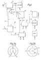
- Figure 1 shows the block diagram of a circuit for performing the first embodiment according to the invention.
- the circuit includes a time base 1 coupled to a frequency divider 2, which provides signals at 32 Hz; at 16 Hz and at 1 min., and a motor of which only the excitation coil 3 is represented and which receives control pulses from a shaping circuit 4.
- the diagram further comprises a manual control 5 acting on a sequencer 11, a frequency selector 12, a first counter 7 giving the reference of the actual hour and minute, a second counter 8 giving the reference of the position of the hands, a memory 21 giving the midi reference on the dial of the timepiece, a first comparator 22 comparing the content of the second counter 8 with the content of the memory 21 and a second comparator 23 comparing the content of the first counter 7 with the content of the second counter 8.
- the elements of the circuit are brought together as illustrated in the diagram in FIG. 1. Five stages can be distinguished.
- 1st stage Normal display of the hour and the minute.
- the selector 12 receives no information from the comparators 22 and 23. It is then connected to position a and transmits the pulses of real time of one minute to the motor 3, via the shaping circuit 4.
- the minute hand then advances one step per minute.
- the reference of its position as well as the position of the hour hand is also stored in the counter 8 via line 13.
- the counter 8 has a capacity of 12 x 60.
- 2nd step Positioning of the two needles at noon.
- the control device 5 is actuated for the first time.
- the signal which results therefrom switches the sequencer 11 and sensitizes the comparator 22 by the line 14.
- the selector 12 is switched to c by the line 15, which results in sending to the motor 3 a 32 Hz fast forward signal for the minute hand.
- the comparator 22 sends via the line 15 a switching signal to the selector 12 which moves to position d. Motor 3 then receives no impulse and stops.
- 3rd step Display of the second. Command 5 is actuated a second time.
- the sequencer 11, via line 24, acts simultaneously, on the one hand, on the selector 12 which it positions at b and, on the other hand, on the divider 25 which transforms the signal at 16 Hz which it receives into signal to one second that it transmits to terminal b of the selector 12.
- the divider 25 makes it possible to reduce the starting time of the timing and thus to increase its precision. Frequencies higher than that of 16 Hz could be chosen if one wished to further increase this precision.
- the minute hand therefore becomes a second hand and progresses by 6 ° per second while the hour hand which is mechanically linked to it becomes a minute hand progressing by 30 ° per minute.
- the position of the display of the minute and second hands is stored in the counter 8 by line 13, as explained in connection with step 1.
- 5th step Return to the normal hour and minute display.
- Command 5 is actuated a fourth time.
- the signal which results therefrom switches the sequencer 11 and sensitizes the comparator 23 by the line 18.
- the comparator 23 sends via the line 19 a switching signal to the selector 12 which moves to position a.
- the motor then receives pulses at one minute, which advances the minute hand by a step of 6 ° per minute and the hour hand by an angle of 30 ° per hour.
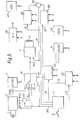
- Figure 3 shows the block diagram of a circuit for performing the second embodiment according to the invention.
- the position of the hands relative to an additional 6-hour reference will be located.
- the hands indicate an actual time of less than 6 hours compared to noon (for example 5 hours)
- the hands will go to position on noon in reverse according to the direction - of the arrow
- said hands indicate an actual time of more than 6 hours compared to noon (for example 7 hours) the hands will go to position for noon in forward direction in the direction + of the arrow.
- the hands will go position in reverse on the real time according to the direction - of the arrow, whereas if the hands indicate a stop timing located more than 6 hours (for example 9 hours) of the real time (for example 2 hours) , the hands will go to forward position on the real time according to the + direction of the arrow.
- the proposed arrangement thus saves time since the hands gain their new starting positions by the shortest route.
- the diagram in FIG. 3 comprises, in addition to the arrangement described in connection with the arrangement gement shown in FIG. 1 and which is reproduced here in its entirety, the following additional elements: a subtractor 26 of content D which subtracts the content A of the first counter 7 from the content B of the second counter 8, a memory 27 comprising a number of pulses corresponding to 6:00 am and content E, a third comparator 28 comparing the content D of the subtractor 26 with the content E of the memory 27 and a fourth comparator 29 comparing the content B of the second counter 8 with the content E of the memory 27.
- the elements of the circuit are brought together as illustrated in Figure 3. As in the first embodiment, we can distinguish five stages. Only steps 2 and 5 will be described here because they differ from those that have been explained above.
- 2nd step Positioning of the two hands at noon.
- the control device 5 is actuated for the first time.
- the signal which results therefrom switches the sequencer 11 which, on the one hand, sensitizes the comparator 22 by the line 14 and switches to c the selector 12 by the line 15 and, on the other hand, sensitizes the comparator 29 by line 30.
- the comparator 22 sends via line 15 a switching signal to the selector 12 which moves to position d. The motor 3 then no longer receives any impulse and stops.
- the comparator 23 sends by the line 19 a switching signal to the selector 12 which moves to position a.
- the motor 3 then receives pulses at one minute, which advances the minute hand by a step of 6 ° per minute and the hour hand at an angle of 30 ° per hour.
- the timepiece only includes the hour and minute hands. Since we want a simplified movement, it will not include an indication of the date. If, however, this should be the case, means similar to those described will be used to add a reference to the position of the date to the circuit.
- a stepping motor having two directions of rotation is necessary.
- reversing the direction of the control pulses will suffice to reverse the direction of rotation of the motor.
- a bipolar motor a special composite signal with alternating polarities will achieve the same result.
Landscapes
- Physics & Mathematics (AREA)
- General Physics & Mathematics (AREA)
- Electromechanical Clocks (AREA)
- Measurement Of Unknown Time Intervals (AREA)
Applications Claiming Priority (2)
| Application Number | Priority Date | Filing Date | Title |
|---|---|---|---|
| FR7925528A FR2467429A1 (fr) | 1979-10-09 | 1979-10-09 | Piece d'horlogerie avec affichage de la seconde sur demande |
| FR7925528 | 1979-10-09 |
Publications (1)
| Publication Number | Publication Date |
|---|---|
| EP0027250A1 true EP0027250A1 (fr) | 1981-04-22 |
Family
ID=9230662
Family Applications (1)
| Application Number | Title | Priority Date | Filing Date |
|---|---|---|---|
| EP80106096A Ceased EP0027250A1 (fr) | 1979-10-09 | 1980-10-08 | Pièce d'horlogerie avec affichage de la seconde sur demande |
Country Status (4)
| Country | Link |
|---|---|
| US (1) | US4364668A (OSRAM) |
| EP (1) | EP0027250A1 (OSRAM) |
| JP (1) | JPS56103387A (OSRAM) |
| FR (1) | FR2467429A1 (OSRAM) |
Cited By (3)
| Publication number | Priority date | Publication date | Assignee | Title |
|---|---|---|---|---|
| EP0059164A1 (fr) * | 1981-02-16 | 1982-09-01 | Compagnie des Montres Longines, Francillon S.A. | Montre multifonctionnelle |
| CH662237GA3 (OSRAM) * | 1985-11-22 | 1987-09-30 | ||
| EP0617346A1 (fr) * | 1993-03-23 | 1994-09-28 | Eta SA Fabriques d'Ebauches | Montre-chronographe avec indicateur de quantième |
Families Citing this family (3)
| Publication number | Priority date | Publication date | Assignee | Title |
|---|---|---|---|---|
| JPS5712386A (en) * | 1980-06-24 | 1982-01-22 | Citizen Watch Co Ltd | Analog timepiece with stopwatch function |
| JPS60224088A (ja) * | 1984-04-20 | 1985-11-08 | Citizen Watch Co Ltd | 指針式タイマ |
| JP2542939B2 (ja) * | 1990-01-16 | 1996-10-09 | セイコー電子工業株式会社 | ストップウォッチ付アナログ電子時計 |
Citations (4)
| Publication number | Priority date | Publication date | Assignee | Title |
|---|---|---|---|---|
| FR2398334A1 (fr) * | 1977-07-18 | 1979-02-16 | Berney Sa Jean Claude | Piece d'horlogerie electronique |
| FR2404250A1 (fr) * | 1977-09-27 | 1979-04-20 | Berney Sa Jean Claude | Piece d'horlogerie electronique |
| GB2026215A (en) * | 1978-07-13 | 1980-01-30 | Berney Sa J | Electronic timepiece with analog display |
| FR2442433A1 (fr) * | 1978-11-21 | 1980-06-20 | Berney Sa Jean Claude | Dispositif d'affichage analogique |
-
1979
- 1979-10-09 FR FR7925528A patent/FR2467429A1/fr active Granted
-
1980
- 1980-10-07 US US06/195,217 patent/US4364668A/en not_active Expired - Lifetime
- 1980-10-08 EP EP80106096A patent/EP0027250A1/fr not_active Ceased
- 1980-10-09 JP JP14066380A patent/JPS56103387A/ja active Pending
Patent Citations (4)
| Publication number | Priority date | Publication date | Assignee | Title |
|---|---|---|---|---|
| FR2398334A1 (fr) * | 1977-07-18 | 1979-02-16 | Berney Sa Jean Claude | Piece d'horlogerie electronique |
| FR2404250A1 (fr) * | 1977-09-27 | 1979-04-20 | Berney Sa Jean Claude | Piece d'horlogerie electronique |
| GB2026215A (en) * | 1978-07-13 | 1980-01-30 | Berney Sa J | Electronic timepiece with analog display |
| FR2442433A1 (fr) * | 1978-11-21 | 1980-06-20 | Berney Sa Jean Claude | Dispositif d'affichage analogique |
Non-Patent Citations (1)
| Title |
|---|
| PATENTS ABSTRACTS OF JAPAN, Vol. 2, No. 109, 9 Septembre 1978 page 6033E78 & JP-A-53 076 070 (DAINI SEIKOSHA K.K.) (06.07.1978). * |
Cited By (6)
| Publication number | Priority date | Publication date | Assignee | Title |
|---|---|---|---|---|
| EP0059164A1 (fr) * | 1981-02-16 | 1982-09-01 | Compagnie des Montres Longines, Francillon S.A. | Montre multifonctionnelle |
| CH662237GA3 (OSRAM) * | 1985-11-22 | 1987-09-30 | ||
| FR2603722A1 (fr) * | 1985-11-22 | 1988-03-11 | Rolex Montres | Chronometre de depart de course, notamment de regate |
| EP0617346A1 (fr) * | 1993-03-23 | 1994-09-28 | Eta SA Fabriques d'Ebauches | Montre-chronographe avec indicateur de quantième |
| US5473580A (en) * | 1993-03-23 | 1995-12-05 | Eta Sa Fabrique D'ebauches | Chronograph watch with date indicator |
| CH686106GA3 (fr) * | 1993-03-23 | 1996-01-15 | Eta Sa | Montre-chronographe avec indicateur de quantieme. |
Also Published As
| Publication number | Publication date |
|---|---|
| FR2467429B1 (OSRAM) | 1983-02-25 |
| FR2467429A1 (fr) | 1981-04-17 |
| JPS56103387A (en) | 1981-08-18 |
| US4364668A (en) | 1982-12-21 |
Similar Documents
| Publication | Publication Date | Title |
|---|---|---|
| EP0698983B1 (fr) | Radiotéléphone intégré dans une montre bracelet dont la couronne permet la composition d'un numéro d'appel | |
| EP0735442B1 (fr) | Pièce d'horlogerie électronique analogique à disque de quantième multifunctionnel | |
| EP0589465B1 (fr) | Pièce d'horlogerie analogique comportant des moyens d'avertissement d'un changement de mode | |
| EP0148414B1 (fr) | Mouvement d'horlogerie comportant plusieurs moteurs pas à pas et une base de temps électronique | |
| FR2492550A1 (fr) | Montre ou horloge a moteur commandee par un oscillateur electrique | |
| EP0059164B1 (fr) | Montre multifonctionnelle | |
| CH704948B1 (fr) | Montre chronographe électromécanique à affichage rétrograde. | |
| EP0027250A1 (fr) | Pièce d'horlogerie avec affichage de la seconde sur demande | |
| CH688299B5 (fr) | Montre électronique avec fonction répétition minutes. | |
| EP0759584B1 (fr) | Dispositif de synchronisation pour pièce d'horlogerie électronique | |
| EP0247418A1 (fr) | Montre calendrier perpétuel à deux moteurs | |
| EP0130150B1 (fr) | Chronographe électronique, notamment montre-chronographe électronique, analogique, compteur de temps chronométrés | |
| EP1807738A2 (fr) | Piece d'horlogerie electronique du type montre multifonctions d'aide a la navigation, notamment pour une mission spatiale | |
| EP1475681A1 (fr) | Montre-chronographe à affichage instantané de fractions de seconde | |
| EP0657792B1 (fr) | Chronographe électronique analogique à rattrapante | |
| EP0202495B1 (fr) | Minuterie | |
| EP0028414A1 (fr) | Pièce d'horlogerie comportant un dispositif de stockage | |
| EP4105738B1 (fr) | Montre comprenant une fonction auxiliaire permettant l'indication des secondes | |
| EP1085384A1 (fr) | Montre chronographe électronique | |
| CH718619B1 (fr) | Montre dotée d'un organe de commande permettant de relancer la course d'une aiguille préalablement interrompue. | |
| EP0357633B1 (fr) | Procede pour afficher une information a base horaire memorisee sur un cadran de montre, et montre equipee pour mettre en oeuvre ce procede | |
| EP1475682A1 (fr) | Montre-chronographe à affichage instantané de fractions de seconde | |
| CH718725A2 (fr) | Montre comprenant une fonction auxiliaire permettant de commander une disposition colinéaire des aiguilles. | |
| CH685142B5 (fr) | Montre-chronographe comportant deux poussoirs à l'exclusion de toute tige-couronne. | |
| CH718618A2 (fr) | Montre dotée d'un organe de commande permettant d'activer une fonction variant suivant une plage horaire dans laquelle ledit organe de commande est sollicité. |
Legal Events
| Date | Code | Title | Description |
|---|---|---|---|
| PUAI | Public reference made under article 153(3) epc to a published international application that has entered the european phase |
Free format text: ORIGINAL CODE: 0009012 |
|
| AK | Designated contracting states |
Designated state(s): CH DE GB |
|
| 17P | Request for examination filed |
Effective date: 19811019 |
|
| STAA | Information on the status of an ep patent application or granted ep patent |
Free format text: STATUS: THE APPLICATION HAS BEEN REFUSED |
|
| 18R | Application refused |
Effective date: 19841126 |
|
| RIN1 | Information on inventor provided before grant (corrected) |
Inventor name: GAGNEBIN, PIERRE-LUC Inventor name: GINALSKI, PIERRE |