EP0026701B1 - Dispositif d'entraînement pour sonde de contrôle de tubes - Google Patents
Dispositif d'entraînement pour sonde de contrôle de tubes Download PDFInfo
- Publication number
- EP0026701B1 EP0026701B1 EP80401344A EP80401344A EP0026701B1 EP 0026701 B1 EP0026701 B1 EP 0026701B1 EP 80401344 A EP80401344 A EP 80401344A EP 80401344 A EP80401344 A EP 80401344A EP 0026701 B1 EP0026701 B1 EP 0026701B1
- Authority
- EP
- European Patent Office
- Prior art keywords
- probe
- passage
- cable
- bore
- casing
- Prior art date
- Legal status (The legal status is an assumption and is not a legal conclusion. Google has not performed a legal analysis and makes no representation as to the accuracy of the status listed.)
- Expired
Links
- 239000000523 sample Substances 0.000 claims description 50
- 239000012530 fluid Substances 0.000 claims description 29
- 238000004891 communication Methods 0.000 claims description 14
- 238000001514 detection method Methods 0.000 claims description 5
- 238000000605 extraction Methods 0.000 claims description 2
- 238000006073 displacement reaction Methods 0.000 claims 2
- 238000011835 investigation Methods 0.000 claims 1
- 240000007817 Olea europaea Species 0.000 description 8
- 238000005259 measurement Methods 0.000 description 3
- 241000207836 Olea <angiosperm> Species 0.000 description 2
- 238000013016 damping Methods 0.000 description 2
- 230000000694 effects Effects 0.000 description 2
- 230000035939 shock Effects 0.000 description 2
- 241001080024 Telles Species 0.000 description 1
- 238000010276 construction Methods 0.000 description 1
- 238000013461 design Methods 0.000 description 1
- 239000007788 liquid Substances 0.000 description 1
- 238000012544 monitoring process Methods 0.000 description 1
- 210000000056 organ Anatomy 0.000 description 1
- 230000035515 penetration Effects 0.000 description 1
- 238000012549 training Methods 0.000 description 1
Images
Classifications
-
- G—PHYSICS
- G01—MEASURING; TESTING
- G01N—INVESTIGATING OR ANALYSING MATERIALS BY DETERMINING THEIR CHEMICAL OR PHYSICAL PROPERTIES
- G01N27/00—Investigating or analysing materials by the use of electric, electrochemical, or magnetic means
- G01N27/72—Investigating or analysing materials by the use of electric, electrochemical, or magnetic means by investigating magnetic variables
- G01N27/82—Investigating or analysing materials by the use of electric, electrochemical, or magnetic means by investigating magnetic variables for investigating the presence of flaws
- G01N27/90—Investigating or analysing materials by the use of electric, electrochemical, or magnetic means by investigating magnetic variables for investigating the presence of flaws using eddy currents
- G01N27/9013—Arrangements for scanning
- G01N27/902—Arrangements for scanning by moving the sensors
Definitions
- the invention relates to a probe drive device for monitoring tubes such as heat exchanger tubes, for example by means of eddy current measurement probes.
- Known devices which make it possible to control the tubes of devices such as heat exchangers by means of eddy current probes are generally pneumatic devices of the puller-pusher-winder type which are particularly heavy and which are not always automatic. .
- document FR-A-2 339 231 relates to a known device in which the probe is introduced and removed by means of a puller-pusher-winder system.
- This device is more particularly suited to the case where the tubes to be checked have bent parts. In these bent parts, the tubes offer greater resistance to the movement of the probe, so that a source of pressurized fluid is provided which delivers an additional force when the probe is introduced.
- the invention aims to provide a drive device for control probe which is both portable and automatic and which makes it possible to introduce the probe as quickly as possible. possible in the tube and bring it back to a regular speed and preferably adjustable.
- a drive device for a tube control probe, and in particular for an eddy current measurement probe, this device comprising a cable to which the probe is connected, electrical drive means capable of acting on said cable, and a source of pressurized fluid, characterized in that it further comprises means for detecting the extreme front and rear positions of the probe in the tube, an automatic pressurized fluid control system comprising a housing defining a first bore and a slide-out slide in said bore, the housing comprising a first inlet port which communicates with the source of pressurized fluid and at least one outlet port which communicates with the tube to be checked behind the probe, and means for implementing the electrical drive means sensitive to the position of the drawer in said bore, the drawer being sensitive to the use of detection means ection front and rear to move in said bore so as either to put the inlet port in communication with said outlet port, or to actuate the means for implementing the electrical drive means, respectively.
- the electric drive means define a constant and adjustable speed of extraction of the probe.
- the housing has a second outlet orifice which communicates with a pressure switch constituting the means for implementing the electrical drive means.
- the electrical drive means can act on the cable via clutch means normally disengaged.
- These clutch means then comprise at least two rollers capable of engaging the cable by friction under the action of the pressurized fluid coming from the second outlet orifice, against elastic return means.
- the detection means comprise a front member and a rear member carried by the cable, said members being capable of closing a front leak orifice and a rear leak orifice communicating with the source of fluid under pressure when the probe reaches the extreme front position and the extreme rear position, respectively, so as to control the operation of the automatic control system.
- the cable is then received in a passage formed in the housing, this passage defining a front part and a rear part intended to receive the front member and the rear member respectively, the front and rear leakage orifices opening out respectively in the front part and in the rear part of the passage.
- the housing can be produced in two articulated parts whose joint plane passes through the axis of said passage, which allows the cable and the probe to be placed inside the device.
- the electrical drive means are then placed in one of said parts and the automatic control system is placed in the other part.
- the front and rear members each comprise a part fixed to the cable, a part capable of closing the corresponding leakage orifice, and damping means arranged between said parts.
- the automatic control system further comprises a first piston received sliding in said bore and defining with the wall of the housing a front chamber communicating with the front leak orifice, so that the closing of the latter by the front member controls the movement of the first piston and of the drawer, so as to interrupt the communication between the inlet port and the first outlet port and to actuate the means for implementing the electric drive means.
- the automatic control system further comprises a second piston received in sliding in a second bore and defining with the wall of the housing a rear chamber communicating with the inlet orifice and with the rear leakage orifice, the housing further defining an exhaust orifice communicating with the atmosphere, the second piston being urged by elastic means towards a position in which the communication between the second inlet orifice and the orifice exhaust is interrupted, and the closing of the rear leakage orifice by the rear member controlling the movement of the second piston against the elastic means so as to establish said communication.
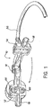
- the drive device As illustrated in particular in FIG. 1, the drive device according to the invention, generally designated by the reference 10, comprises a housing in two parts 12 and 14 articulated around an axis 16.
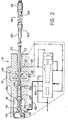
- the joint plane of the parts 12 and 14 of the housing passes by the axis of a passage 18 intended to receive a cable 20 to which a tube control probe 22 is connected, such as an eddy current measurement probe, as illustrated in particular in FIG. 2.
- the drive device 10 according to the invention is designed so as to introduce the probe 22 as quickly as possible into a straight tube of known length which it is necessary to control, in known manner, by means of the probe 22 during the return thereof to the device, this return being preferably carried out at a regular and adjustable speed.
- the tubes to be controlled automatically in this way are generally arranged in devices having a large number of tubes such as condensers, heat exchangers or steam generators.
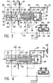
- the drive device 10 comprises an automatic pressure fluid control system generally designated by the reference 24, arranged in the part 14 of the housing.
- the system 24 comprises a slide 26 received slidingly in a stepped bore 28 formed in the part 14 of the housing.
- the drawer 26 as well as the bore 28 comprise a large diameter part and a small diameter part defining between them shoulders on which a spring 30 comes to bear, urging the drawer 26 to the right when considering FIG. 3, in abutment against a piston 32 disposed between the right end of the slide 26 and the bottom of the bore 28.
- an inlet chamber 34 is formed between the left end of the drawer 26 and the part 14 of the housing communicates with a source of pressurized fluid (shown diagrammatically by an arrow), through an inlet 36 to which is connected a flexible pipe 38 shown in FIG. 1.
- the chamber 34 also communicates through an outlet orifice 40 and via a passage shown diagrammatically at 42 with a large diameter portion 43 of the passage 18 intended to receive the probe 22, as illustrated in FIG. 2.
- the orifice 40 is slightly offset to the right with respect to the passage 36, as illustrated in particular in FIG. 3, so that it is closed by the slide 26 when the latter moves to the left against the spring 30, before the slide comes into abutment against the left end of the bore 28.
- the inlet 36 communicates permanently with an annular chamber 44 defined in the large-diameter portion of the drawer 26 by a longitudinal passage 46 formed therein.
- the annular chamber 44 communicates by an outlet orifice 48 and by a passage 50, with a rear leakage orifice 52 opening into a part 53 of the passage 18 located near the end of that opposite to the probe 22, when the slide 26 is in the rest position.
- the annular chamber 44 communicates via a second outlet orifice 54 and a passage 56 with a pressure switch 58 controlling the implementation of an electric drive motor (not shown) and with two chambers 62 controlling the movement of two pistons 60 towards each other against a spring 64 disposed between the pistons 60 , so as to urge two drive rollers 66 in friction engagement with the cable 20.
- the electric drive motor whose implementation is controlled by the pressure switch 58 biases the rollers 66 which thus frictionally drive the cable 20 in the direction corresponding to the return of the probe 22 to the device 10, as will be seen later.
- a front chamber 68 defined between the piston 32 and the bottom of the bore 28 communicates through an orifice 70 and through a passage 72 with the leakage passage 50, and a chamber 74 defined between the piston 32 and the slide 26 communicates by an orifice 76 and by a passage 78 with the passage 56.
- the chamber containing the spring 30 communicates permanently with the atmosphere by an orifice 80 and by a passage 82.
- a second bore 84 is provided in the housing 14, in the extension of the bore 28 on the side opposite to the piston 32.
- the bore 84 slidably receives a second piston 88 biased towards the right considering Fig. 3 by a spring 90 disposed between the piston 88 and the end of the bore 84 opposite the bore 28.
- the chamber receiving the spring 90 communicates with the atmosphere through an orifice 92 and a passage 94.
- a rear chamber 96 defined between the piston 88 and the other end of the bore 84 communicates with the inlet chamber 34 by a passage 86 and comprises an outlet orifice 98 which communicates by a passage 100 with a front leakage orifice 102 opening into a part 103 of passage 18 situated behind the large diameter part 43 intended to receive the probe 22.
- the piston 88 has in its central part a groove 104 capable of establishing communication a second inlet port 106 with an exhaust port 108 when the pressure prevailing in the chamber 96 displaces the piston 88 against the force exerted by the spring 90.
- the port 106 communicates by a passage 110 with the passage 56 and ori fice 108 communicates through a passage 112 with the passage 82, so that the pressure switch 58 and the chambers 62 are vented when the piston 88 occupies this position.
- the front 102 and rear 52 leakage orifices can be closed off respectively by a front member 114 and by a rear member 116.
- Each of the members 114 and 116 comprises a collar 118 fixed rigidly to the cable 20 and an olive 120 capable of sliding relative to the cable 20 and connected to the collar 118 by a damping spring 122.
- the olives 120 of each from organs 114 and 116 are arranged on the side of the device housing drive 10 relative to the collar 118, so as to penetrate into the parts 103 and 53 of the passage 18, in which the orifices 102 and 52 are respectively provided and to come into abutment by a shoulder 124 against the corresponding ends of the said parts when the probe 22 occupies its extreme front position or its extreme rear position relative to the tube to be explored.
- the free end of part 43 of passage 18 is connected to this tube, for example by bringing it directly in front of it.
- Pressurized fluid from the source (not shown) is then admitted into the chamber 34 via the flexible conduit 38 and the inlet orifice 36.
- This fluid is admitted directly into the part 43 of the passage 18 , through the outlet 40 and the passage 42, so that the probe 22 as well as the cable 20 and the members 114 and 116 which are associated with it are biased to the left when considering FIG. 2 inside the tube to be checked (not shown).
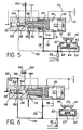
- the front leakage opening 102 is immediately opened and the pressure falls in the chamber 96, so that the piston 88 is moved to the right under the action of the spring 90, which has the effect of interrupting the communication between the holes 106 and 108, as illustrated in FIG. 4.
- the pressurized fluid admitted into the chamber 34 is also communicated to the rear leakage orifice 52 via the passage46, the annular chamber44, the orifice 48 and the passage 50, and to the orifice leak before 102 via passage 86, chamber 96, orifice 98 and passage 100. Since the olives 120 are then both distant from the corresponding parts 53 and 103 of passage 18, the fluid under pressure escaping through the orifices 52 and 102 is communicated to the atmosphere and has no effect on the functioning of the system 24.
- the introduction of the probe 22 into the tube to be controlled being carried out directly under the action of the pressurized fluid is therefore extremely rapid.
- the design and construction of the probe drive device according to the invention are particularly simple and make it possible to produce it in the form of a portable gun with a single control capable of being brought successively facing each of the tubes of the device to be checked. All the movements of the probe inside the tube are carried out by operating a single control associated with the source of pressurized fluid (not shown), making it possible to communicate the pressurized fluid, by the flexible pipe 38, to the inlet 36 of the automatic control system 24.
- the latter then automatically controls, successively the rapid introduction of the probe into the tube by pressurized fluid, the interruption of the communication of pressurized fluid between the source and the tube to be checked when the probe reaches its extreme front position, the clutch and the use of the constant and adjustable speed drive means constituted by the electric drive motor (not shown) and the rollers 66, da so as to control the tube by bringing the probe back to the desired constant speed, and finally disengaging and stopping the electric drive means when the probe reaches its rear extreme position shown in FIG. 2.
Landscapes
- Chemical & Material Sciences (AREA)
- Chemical Kinetics & Catalysis (AREA)
- Electrochemistry (AREA)
- Physics & Mathematics (AREA)
- Health & Medical Sciences (AREA)
- Life Sciences & Earth Sciences (AREA)
- Analytical Chemistry (AREA)
- Biochemistry (AREA)
- General Health & Medical Sciences (AREA)
- General Physics & Mathematics (AREA)
- Immunology (AREA)
- Pathology (AREA)
- Investigating Or Analyzing Materials By The Use Of Magnetic Means (AREA)
- Investigating Or Analyzing Materials By The Use Of Ultrasonic Waves (AREA)
Applications Claiming Priority (2)
| Application Number | Priority Date | Filing Date | Title |
|---|---|---|---|
| FR7924048A FR2466766A1 (fr) | 1979-09-27 | 1979-09-27 | Dispositif d'entrainement pour sonde de controle de tubes |
| FR7924048 | 1979-09-27 |
Publications (2)
| Publication Number | Publication Date |
|---|---|
| EP0026701A1 EP0026701A1 (fr) | 1981-04-08 |
| EP0026701B1 true EP0026701B1 (fr) | 1983-12-07 |
Family
ID=9230068
Family Applications (1)
| Application Number | Title | Priority Date | Filing Date |
|---|---|---|---|
| EP80401344A Expired EP0026701B1 (fr) | 1979-09-27 | 1980-09-19 | Dispositif d'entraînement pour sonde de contrôle de tubes |
Country Status (4)
| Country | Link |
|---|---|
| US (1) | US4389611A (OSRAM) |
| EP (1) | EP0026701B1 (OSRAM) |
| DE (1) | DE3065836D1 (OSRAM) |
| FR (1) | FR2466766A1 (OSRAM) |
Families Citing this family (9)
| Publication number | Priority date | Publication date | Assignee | Title |
|---|---|---|---|---|
| DE3202883C2 (de) * | 1982-01-29 | 1986-09-18 | Kraftwerk Union AG, 4330 Mülheim | Bewegungseinrichtung zum Antrieb einer Sonde |
| FR2524133B1 (fr) * | 1982-03-26 | 1986-01-31 | Framatome Sa | Dispositif de controle de la plaque tubulaire d'un echangeur de chaleur |
| FR2539510A1 (fr) * | 1983-01-18 | 1984-07-20 | Commissariat Energie Atomique | Dispositif de controle de tubes cintres a sonde propulsee pneumatiquement |
| US4703817A (en) * | 1984-12-28 | 1987-11-03 | Westinghouse Electric Corp. | Controllable vehicle for inspecting limited access areas |
| US4757258A (en) * | 1985-11-27 | 1988-07-12 | Westinghouse Electric Corp. | Probe carrier system for inspecting boiler tubes |
| US4760876A (en) * | 1986-09-02 | 1988-08-02 | Westinghouse Electric Corp. | Remote inspection device transport system |
| DE3843123A1 (de) * | 1988-12-22 | 1990-06-28 | Foerster Inst Dr Friedrich | Vorrichtung zum bewegen von schubschlaeuchen im inneren von rohren |
| US5025215A (en) * | 1989-08-16 | 1991-06-18 | Westinghouse Electric Corp. | Support equipment for a combination eddy current and ultrasonic testing probe for inspection of steam generator tubing |
| US5440297A (en) * | 1993-12-27 | 1995-08-08 | Bright; Robert I. | Electrician's fish tape locator system |
Family Cites Families (4)
| Publication number | Priority date | Publication date | Assignee | Title |
|---|---|---|---|---|
| US3277420A (en) * | 1963-12-09 | 1966-10-04 | Plastic Applicators | Hydraulically operated clamping mechanism |
| US3495546A (en) * | 1967-11-03 | 1970-02-17 | American Mach & Foundry | Speed control device for pipeline inspection apparatus |
| US3906358A (en) * | 1973-11-12 | 1975-09-16 | Combustion Eng | Probe train including a flaw detector and a radiation responsive recording means with alignment means having a natural curved cast |
| FR2339231A1 (fr) * | 1976-01-22 | 1977-08-19 | Commissariat Energie Atomique | Dispositif d'entrainement pneumatique pour sonde de mesure a courants de foucault |
-
1979
- 1979-09-27 FR FR7924048A patent/FR2466766A1/fr active Granted
-
1980
- 1980-09-19 DE DE8080401344T patent/DE3065836D1/de not_active Expired
- 1980-09-19 EP EP80401344A patent/EP0026701B1/fr not_active Expired
- 1980-09-25 US US06/190,876 patent/US4389611A/en not_active Expired - Lifetime
Also Published As
| Publication number | Publication date |
|---|---|
| US4389611A (en) | 1983-06-21 |
| FR2466766B1 (OSRAM) | 1981-10-23 |
| DE3065836D1 (en) | 1984-01-12 |
| EP0026701A1 (fr) | 1981-04-08 |
| FR2466766A1 (fr) | 1981-04-10 |
Similar Documents
| Publication | Publication Date | Title |
|---|---|---|
| EP0026701B1 (fr) | Dispositif d'entraînement pour sonde de contrôle de tubes | |
| EP0017592B1 (fr) | Dispositif d'actionnement hydraulique à cinq positions | |
| EP0088017B1 (fr) | Dispositif de distribution hydraulique à tiroir | |
| CH617506A5 (OSRAM) | ||
| FR2475221A1 (fr) | Dispositif d'essai de circuits hydrauliques | |
| CA2108185C (fr) | Dispositif support d'une sonde de detection et de localisation de defauts eventuels a l'interieur d'un alesage | |
| CA1162130A (fr) | Convertisseur de couple hydrodynamique muni de moyens de pontage | |
| EP0670971B1 (fr) | Embrayage de vehicule automobile a actionnement hydraulique comportant des moyens d'indication d'usure | |
| EP0808686B1 (fr) | Dispositif d'emmanchement d'un joint d'étanchéité sur un arbre | |
| EP0144337B1 (fr) | Dispositif economiseur automatique d'air comprime | |
| FR2528545A1 (fr) | Dispositif automatique d'arret de l'alimentation en combustible fluide d'un equipement de combustion | |
| EP0162793A1 (fr) | Dispositif pour actionner une boîte à vitesses dont la synchronisation est pilotée par un calculateur électronique | |
| EP0061960B1 (fr) | Correcteur de freinage pour véhicule automobile asservi à la décélération | |
| FR2756003A1 (fr) | Dispositif de forage | |
| FR2632010A1 (fr) | Dispositif d'ancrage d'une sonde dans un puits par ecartement de bras d'ancrage mobiles | |
| CH624595A5 (OSRAM) | ||
| EP0007278B1 (fr) | Maître-cylindre tandem | |
| CA1248214A (fr) | Dispositif perfectionne pour produire dans l'eau des ondes acoustiques | |
| FR2487539A1 (fr) | Servosysteme electro-hydraulique a blocage de position en cas de defaut | |
| EP0004513A1 (fr) | Dispositif de commande hydropneumatique synchronisée d'embrayage et de verrouillage de boîte de vitesses | |
| FR2747174A1 (fr) | Distributeur hydraulique pour servocommandes d'aeronefs, notamment helicopteres | |
| FR2749909A1 (fr) | Dispositif de securite pour boite de vitesses mecanique | |
| FR2517235A1 (fr) | Ensemble porte-outil tel que perceuse | |
| EP0229545B1 (fr) | Dispositif de commande en déplacement d'un organe mobile, tel qu'un volet dans une installation de chauffage et de ventilation ou de climatisation pour véhicule automobile | |
| FR2481401A1 (fr) | Perfectionnements aux raccords-vannes de securite |
Legal Events
| Date | Code | Title | Description |
|---|---|---|---|
| PUAI | Public reference made under article 153(3) epc to a published international application that has entered the european phase |
Free format text: ORIGINAL CODE: 0009012 |
|
| AK | Designated contracting states |
Designated state(s): BE DE GB IT NL SE |
|
| 17P | Request for examination filed |
Effective date: 19810907 |
|
| ITF | It: translation for a ep patent filed | ||
| GRAA | (expected) grant |
Free format text: ORIGINAL CODE: 0009210 |
|
| AK | Designated contracting states |
Designated state(s): BE DE GB IT NL SE |
|
| REF | Corresponds to: |
Ref document number: 3065836 Country of ref document: DE Date of ref document: 19840112 |
|
| PGFP | Annual fee paid to national office [announced via postgrant information from national office to epo] |
Ref country code: DE Payment date: 19840716 Year of fee payment: 5 |
|
| PGFP | Annual fee paid to national office [announced via postgrant information from national office to epo] |
Ref country code: SE Payment date: 19840930 Year of fee payment: 5 Ref country code: BE Payment date: 19840930 Year of fee payment: 5 |
|
| PLBE | No opposition filed within time limit |
Free format text: ORIGINAL CODE: 0009261 |
|
| STAA | Information on the status of an ep patent application or granted ep patent |
Free format text: STATUS: NO OPPOSITION FILED WITHIN TIME LIMIT |
|
| 26N | No opposition filed | ||
| PGFP | Annual fee paid to national office [announced via postgrant information from national office to epo] |
Ref country code: NL Payment date: 19860930 Year of fee payment: 7 |
|
| PG25 | Lapsed in a contracting state [announced via postgrant information from national office to epo] |
Ref country code: SE Effective date: 19870920 |
|
| PG25 | Lapsed in a contracting state [announced via postgrant information from national office to epo] |
Ref country code: BE Effective date: 19870930 |
|
| BERE | Be: lapsed |
Owner name: COMMISSARIAT A L'ENERGIE ATOMIQUE ETABLISSEMENT D Effective date: 19870930 |
|
| PG25 | Lapsed in a contracting state [announced via postgrant information from national office to epo] |
Ref country code: NL Effective date: 19880401 |
|
| NLV4 | Nl: lapsed or anulled due to non-payment of the annual fee | ||
| PG25 | Lapsed in a contracting state [announced via postgrant information from national office to epo] |
Ref country code: DE Effective date: 19880601 |
|
| GBPC | Gb: european patent ceased through non-payment of renewal fee | ||
| PG25 | Lapsed in a contracting state [announced via postgrant information from national office to epo] |
Ref country code: GB Free format text: LAPSE BECAUSE OF NON-PAYMENT OF DUE FEES Effective date: 19881118 |
|
| EUG | Se: european patent has lapsed |
Ref document number: 80401344.9 Effective date: 19880906 |