EP0026076B1 - Improvements relating to storage and transport containers - Google Patents
Improvements relating to storage and transport containers Download PDFInfo
- Publication number
- EP0026076B1 EP0026076B1 EP19800303219 EP80303219A EP0026076B1 EP 0026076 B1 EP0026076 B1 EP 0026076B1 EP 19800303219 EP19800303219 EP 19800303219 EP 80303219 A EP80303219 A EP 80303219A EP 0026076 B1 EP0026076 B1 EP 0026076B1
- Authority
- EP
- European Patent Office
- Prior art keywords
- box
- storage
- hoops
- transport container
- container according
- Prior art date
- Legal status (The legal status is an assumption and is not a legal conclusion. Google has not performed a legal analysis and makes no representation as to the accuracy of the status listed.)
- Expired
Links
Images


Classifications
-
- F—MECHANICAL ENGINEERING; LIGHTING; HEATING; WEAPONS; BLASTING
- F42—AMMUNITION; BLASTING
- F42B—EXPLOSIVE CHARGES, e.g. FOR BLASTING, FIREWORKS, AMMUNITION
- F42B39/00—Packaging or storage of ammunition or explosive charges; Safety features thereof; Cartridge belts or bags
-
- Y—GENERAL TAGGING OF NEW TECHNOLOGICAL DEVELOPMENTS; GENERAL TAGGING OF CROSS-SECTIONAL TECHNOLOGIES SPANNING OVER SEVERAL SECTIONS OF THE IPC; TECHNICAL SUBJECTS COVERED BY FORMER USPC CROSS-REFERENCE ART COLLECTIONS [XRACs] AND DIGESTS
- Y10—TECHNICAL SUBJECTS COVERED BY FORMER USPC
- Y10T—TECHNICAL SUBJECTS COVERED BY FORMER US CLASSIFICATION
- Y10T292/00—Closure fasteners
- Y10T292/08—Bolts
- Y10T292/096—Sliding
- Y10T292/0969—Spring projected
- Y10T292/097—Operating means
- Y10T292/0997—Rigid
-
- Y—GENERAL TAGGING OF NEW TECHNOLOGICAL DEVELOPMENTS; GENERAL TAGGING OF CROSS-SECTIONAL TECHNOLOGIES SPANNING OVER SEVERAL SECTIONS OF THE IPC; TECHNICAL SUBJECTS COVERED BY FORMER USPC CROSS-REFERENCE ART COLLECTIONS [XRACs] AND DIGESTS
- Y10—TECHNICAL SUBJECTS COVERED BY FORMER USPC
- Y10T—TECHNICAL SUBJECTS COVERED BY FORMER US CLASSIFICATION
- Y10T292/00—Closure fasteners
- Y10T292/08—Bolts
- Y10T292/096—Sliding
- Y10T292/1014—Operating means
- Y10T292/1022—Rigid
- Y10T292/1025—Padlock or seal catch
Definitions
- the invention relates to storage and transport containers for elongate articles and has particular though not exclusive application to the storage and transport of ammunition of the size and kind used in military tanks.
- Each shell of such ammunition may for example be in the region of 14 cm in diameter, 90 cm in length and weigh 20 kg.
- One method previously used of storing and transporting such ammunition was to contain each separate shell in an hermetically sealed container, provide a plurality of tubes in a steel box and slide each shell into a respective one of the tubes, the box then being mounted on a pallet for handling by fork-lift trucks and loading into a logistics vehicle for transportation to the site at which a tank was to be armed, the individual shells then being extracted in their containers from the tubes, stripped of their containers and loaded into the tank.
- the containers were liable to damage such that they could frequently not be re-used and there was considerable wasted space in the box formed by dead space between the tubes which could not nestle closely together.
- a storage and transport container for elongate articles comprising a member of generally honeycomb section defining a plurality of elongate recesses, a five sided box surrounding said member of honeycomb section, spacer members secured to the outer faces of the walls of the box, protective hoops encircling the box and secured to said spacer members and a door to close and seal the open side of said box.
- the member of honeycomb section is formed as a stack of corrugated sheets, said sheets being superposed with their corrugations off-set and secured together.
- the protective hoops are secured to the spacer members by way of tie bars which extend between adjacent pairs of said hoops and are secured to said hoops and to said spacer members.
- the corrugated sheets of the stack, the walls of the box and the spacer members are all formed of sheet steel.
- the corrugated sheets are preferably so shaped that the elongate recesses, each formed between two co-operating sheets of the stack of sheets, are of hexagonal section.
- the sheets of the stack are spot-welded together as the stack is built up and the walls of the box are spot-welded to sheets of the stack and are seam welded to each other.
- the hoops and the tie bars are preferably formed of tubular steel, the hoops of circular section and the tie bars of rectangular section.
- the spacers are advantageously elongate members each of top-hat section with the two flanges forming the brim of the top-hat section spot-welded to the walls of the box.
- the elongate spacer members encircle the box so that they extend parallel to the hoops with each spacer member located intermediate an adjacent pair of the hoops.
- the tie bars extend perpendicular to the elongate spacers and to the hoops with the middle portion of each tie bar lying on and welded to the web of the respective top-hat section spacer member forming the crown thereof and with its ends welded to respective ones of the two adjacent ones of the hoops.
- End ones of the hoops extend at positions clear of the ends of the box and on the single end wall of the box further spacer members are provided to reinforce said end wall.
- the door may comprise a surrounding frame, a wire mesh sheet at the inner side of said frame and a glass reinforced plastics cover which engages a seal provided between the cover and the box at the open side thereof.
- the frame of the door at one of its sides is pivotally mounted on an end one of the hoops and at a side opposite to said one side is provided with securing means.
- Clamp screws are preferably provided, screw threadedly engaged in apertures in the frame of the door and engaging the plastics cover at a plurality of positions around its periphery to press the plastics cover away from the frame and into engagement with the seal.
- the door may comprise a panel with sealing means at or adjacent its periphery to engage the box at or adjacent the open side thereof, a framework located on the exterior face of the panel, at least one jack located between and connecting the panel and the framework and a plurality of compression springs extending between the panel and the framework, the framework being engageable at opposite sides thereof with the box such that the force of the springs presses the panel away from the framework towards the box to seal the panel around the open side of the box, which force can be overcome by tensioning the jack to pull the panel outwardly towards the framework.
- the jack is provided as a pair of scissor jacks with a common operating member.
- the framework is engageable with the box at one side by means of hinge pins and at the opposite side by means of a latch arrangement.
- the latch arrangement and the common operating member of the scissor jacks can be engaged one with the other and secured, for example by means of a padlock, to prevent unauthorised opening of the container.
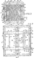
- a storage and transport container for elongate articles comprises a stack of ten corrugated sheets 2, the thicknesses of which are indicated only at the bottom of Figure 1, each comprising alternate angular depressions 3 and raised portions 4 such that with alternate sheets inverted a honeycomb section defining hexagonal elongate recesses is formed, the sheets being spot-welded together as indicated at 5.
- the stack of ten sheets 2 secured together provide twenty-three elongate recesses of hexagonal section, two half hexagonal recesses at the top and at the bottom and a plurality of smaller recesses at the sides.
- the smaller recesses can be used to receive bags of silica gel or similar hydroscopic material.
- a five sided box of sheet steel is formed around the stack of corrugated sheets 2 and comprises opposite side walls 6 and 7, a lower wall 8 and an upper wall 9.
- a rear wall 10 is also provided, the walls 6, 7, 8, 9 and 10 being secured to the corrugated sheets 2 by spot- welding and being seam welded where they abut one with another.
- Spacers 11 are secured along the walls 6, 7, 8 and 9 extending in parallel to the free edges thereof.
- Four spacers 11 are provided on each of the walls 6, 7, 8 and 9 and each spacer 11 is of top-hat section comprising base or brim flanges 12 and 13, side flanges 14 and 15 and a crown flange 16. The ends of the spacers 11 are mitred to join with the aligned spacer on the adjacent faces of the box at joint lines 17.
- Tie bars 18 of rectangular section steel tubing are laid across the crown flanges 16 of the spacers 11 and at their ends abut hoops 19 which are provided of circular section steel tube and each completely encircle the box. Five hoops 19 are provided.
- the ends of the tie bars 18 are welded to the hoops 19 and the tie bars 18 are welded to the crown flanges 16 of the spacers 11.
- the hoop 19 at the front of the box and the hoop 19 at the rear of the box are provided at positions beyond the front end and rear end respectively.
- stiffeners 20 are provided of similar section to the spacers 11 and welded to the rear wall 10.
- a door 26 comprises an outer framework formed by four rectangular section tubular side members 27, the members 27 having a wire mesh grid 28 welded to their inner face. At two positions on each member 27, the member is drilled through and the hole formed is screw threaded to receive a respective clamping screw 29 having a hand wheel 30 at its outer end.
- the lefthand tubular side member 27 as viewed in Figure 3 is secured by jointing members 31 to two tubular sleeves 32 which surround the adjacent portion of the front hoop 19 whereby the frame of the door 26 is hingedly mounted on the front hoop 19.
- the frame side member 27 of the door 26 is provided with securing bolts 33 whereby it can be secured in a closed position, the free ends of the bolts 33 engaging in recesses in lugs 34 provided on the adjacent portions of the front hoop 19.
- Inner ends of the screw threaded members 29 are provided with heads 35 captive in recesses formed by brackets 36 and 37 on a glass reinforced plastics cover 38 having a profiled edge all round its periphery to engage with the seal 25.
- the profiled edge of the cover 38 comprises an outer peripheral projection 39, the inner edge of which slides along the members 23 of the brackets 22 and an inner projection 40 which engages the seal 25.
- FIGS. 3 and 4 show loop handles 41 to facilitate opening the door after the hand wheels 30 have been rotated to free the cover 38 from the seal and the bolts 33 have been retracted.
- a shell for a tank gun Is shown in outline at 42 with half mouldings of expanded polystyrene, shaped to the shell, surrounding it.
- the half mouldings are referenced 43 and 44.
- Protective end portions 45 and 46 are provided for the ends of the shell 42.
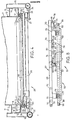
- a door sealing arrangement comprises a door 51 formed as a rectangular sheet steel panel 52 with a central Inwardly dished portion 53 and a peripheral flange 54 mounting a seal 55 comprising a silicone tube 16 millimetres in outside diameter.
- the seal 55 is held in place by a seal retaining channel 56.
- the panel 52 is pressed towards an opening In a container, will engage the container by means of the silicone seal 55 with the dished portion 53 projecting into the container to seal the container and maintain its seal so long as the panel 52 is pressed towards the container.
- first and second levers 58 and 59 respectively of each of a pair of scissor jacks 60 are pivotably mounted, the scissor jacks 60 also comprising second and third levers 61 and 62 respectively.
- the levers 58 and 61 of each scissor jack are pivoted together by means of a pivot pin 83, the levers 59 and 62 of each scissor jack are pivoted together by means of a pivot pin 64 and the levers 61 and 62 of each scissor jack are pivoted together by means of a pivot pin 65 which also passes through a U-shaped bracket 66 of a framework 67.
- the framework 67 comprises a pair of main bars 68 and 69 interconnected by struts 70.
- the main bars 68 and 69 and the struts 70 are of rectangular section.
- Each scissor jack 60 has a screw member 71 comprising a first portion engaged in a transverse screw threaded aperture in the pivot pin 64 and a second portion with an oppositely handed screw thread to the first portion engaged in a transverse screw threaded aperture in the pivot pin 63.
- the screw members 71 of the two scissor jacks are secured together at their adjacent ends by welding them to a cylinder member 73 having a transverse aperture therein at the mid-position in its length.
- the screw members 71 can be rotated to pull the pivot pins 63, 64 of each scissor jack 60 towards one another or by an opposite rotation to press them away from one another.
- each scissor jack 60 Due to the parallelogram linkage 58, 59, 61, 62 of each scissor jack 60, relative movement towards or away from another of the pivot pins 63, 64 will cause the panel 52 and the framework 67 to move towards or away from one another in opposite relation to the pivot pins 63, 64 of the jacks, that is to say if the pivot pins 63, 64 move towards one another then the panel 52 and the framework 67 move away from one another and if the pivot pins 63, 64 move away from one another then the panel 52 and framework 67 move towards one another.
- hollow cylindrical members 75 each of which has a respective coil spring 76 received therein.
- the coil springs 76 bear against a reinforcing and locating member 77 on the outer face of the depressed portion 53 of the panel 52. The force of the springs 76 tends to press the panel 52 and framework 67 away from one another.
- a transverse bore 78 is provided, each to engage on a respective hinge pin provided on the container.
- a latch arrangement 79 is provided including a U-shaped sliding bolt 80 the free ends 81 of which can engage in apertures provided in projections from the container such that by means of the hinge pins and the sliding bolt 80, the framework 67 can be secured against outward movement with respect to the container.
- the arms 82 of the sliding bolt 80 are slidably mounted in bores in blocks 83 carried by the main members 68, 69 of the framework 67 and are biassed by biassing springs 84.
- a bracket 85 connected to the transverse bar 86 of the U-shaped bolt 80 has an end portion 87 with an aperture therein in which the tommy bar 74 of the scissor jacks 60 can be engaged.
- Stacking lugs may be provided on the container together with slinging points to facilitate crane transportation.
- the container 1 can be of 1071 millimetres overall depth, 1041 millimetres overall width, 1200 millimetres overall length and together with its door may have a weight of approximately 275 kilos.
Description
- The invention relates to storage and transport containers for elongate articles and has particular though not exclusive application to the storage and transport of ammunition of the size and kind used in military tanks. Each shell of such ammunition may for example be in the region of 14 cm in diameter, 90 cm in length and weigh 20 kg. One method previously used of storing and transporting such ammunition was to contain each separate shell in an hermetically sealed container, provide a plurality of tubes in a steel box and slide each shell into a respective one of the tubes, the box then being mounted on a pallet for handling by fork-lift trucks and loading into a logistics vehicle for transportation to the site at which a tank was to be armed, the individual shells then being extracted in their containers from the tubes, stripped of their containers and loaded into the tank. The containers were liable to damage such that they could frequently not be re-used and there was considerable wasted space in the box formed by dead space between the tubes which could not nestle closely together.
- Where a container is to be used to store articles for a considerable period, for example fifteen years, it is frequently important that it be hermetically sealed to prevent deterioration of the articles due to atmospheric corrosion. Hermetically sealing a container with a large opening, for example 1 t metres square in a manner such that the container can be transported without breaking the seal, presents considerable problems.
- According to the invention there is provided a storage and transport container for elongate articles comprising a member of generally honeycomb section defining a plurality of elongate recesses, a five sided box surrounding said member of honeycomb section, spacer members secured to the outer faces of the walls of the box, protective hoops encircling the box and secured to said spacer members and a door to close and seal the open side of said box.
- Advantageously, the member of honeycomb section is formed as a stack of corrugated sheets, said sheets being superposed with their corrugations off-set and secured together. Advantageously the protective hoops are secured to the spacer members by way of tie bars which extend between adjacent pairs of said hoops and are secured to said hoops and to said spacer members.
- Preferably the corrugated sheets of the stack, the walls of the box and the spacer members are all formed of sheet steel. The corrugated sheets are preferably so shaped that the elongate recesses, each formed between two co-operating sheets of the stack of sheets, are of hexagonal section. The sheets of the stack are spot-welded together as the stack is built up and the walls of the box are spot-welded to sheets of the stack and are seam welded to each other. The hoops and the tie bars are preferably formed of tubular steel, the hoops of circular section and the tie bars of rectangular section.
- The spacers are advantageously elongate members each of top-hat section with the two flanges forming the brim of the top-hat section spot-welded to the walls of the box. The elongate spacer members encircle the box so that they extend parallel to the hoops with each spacer member located intermediate an adjacent pair of the hoops. The tie bars extend perpendicular to the elongate spacers and to the hoops with the middle portion of each tie bar lying on and welded to the web of the respective top-hat section spacer member forming the crown thereof and with its ends welded to respective ones of the two adjacent ones of the hoops.
- End ones of the hoops extend at positions clear of the ends of the box and on the single end wall of the box further spacer members are provided to reinforce said end wall.
- The door may comprise a surrounding frame, a wire mesh sheet at the inner side of said frame and a glass reinforced plastics cover which engages a seal provided between the cover and the box at the open side thereof. Preferably the frame of the door at one of its sides is pivotally mounted on an end one of the hoops and at a side opposite to said one side is provided with securing means. Clamp screws are preferably provided, screw threadedly engaged in apertures in the frame of the door and engaging the plastics cover at a plurality of positions around its periphery to press the plastics cover away from the frame and into engagement with the seal.
- Alternatively the door may comprise a panel with sealing means at or adjacent its periphery to engage the box at or adjacent the open side thereof, a framework located on the exterior face of the panel, at least one jack located between and connecting the panel and the framework and a plurality of compression springs extending between the panel and the framework, the framework being engageable at opposite sides thereof with the box such that the force of the springs presses the panel away from the framework towards the box to seal the panel around the open side of the box, which force can be overcome by tensioning the jack to pull the panel outwardly towards the framework.
- Preferably the jack is provided as a pair of scissor jacks with a common operating member.
- Advantageously the framework is engageable with the box at one side by means of hinge pins and at the opposite side by means of a latch arrangement. The latch arrangement and the common operating member of the scissor jacks can be engaged one with the other and secured, for example by means of a padlock, to prevent unauthorised opening of the container.
- The invention is diagrammatically illustrated by way of example in the accompanying drawings, in which:-
- Figure 1 is an elevation of the open end of a storage and transport container for elongate articles according to the invention;
- Figure 2 is a side view corresponding to Figure 1;
- Figure 3 is a view similar to Figure 1 but with a lid in position on the container;
- Figure 4 is a sectional view taken on line IV-IV of Figure 3 showing the lid;
- Figure 5 is an elevation of a packing for a shell to be received in the storage and transport container for elongate articles of Figures 1 to 4;
- Figures 6a, 6b and 6c are respectively sections taken on lines A-A, B-B and C-C of Figure 5;
- Figure 7 is an elevation of a door to close an opening of a container according to the invention;
- Figure 8 is a view taken in the direction of arrow VIII of Figure 7; and
- Figure 9 is a view taken in the direction of arrow IX of Figure 7.
- Referring to the drawings and firstly to Figures 1 and 2, a storage and transport container for elongate articles, generally indicated at 1, comprises a stack of ten corrugated sheets 2, the thicknesses of which are indicated only at the bottom of Figure 1, each comprising alternate
angular depressions 3 and raisedportions 4 such that with alternate sheets inverted a honeycomb section defining hexagonal elongate recesses is formed, the sheets being spot-welded together as indicated at 5. The stack of ten sheets 2 secured together provide twenty-three elongate recesses of hexagonal section, two half hexagonal recesses at the top and at the bottom and a plurality of smaller recesses at the sides. The smaller recesses can be used to receive bags of silica gel or similar hydroscopic material. - A five sided box of sheet steel is formed around the stack of corrugated sheets 2 and comprises
opposite side walls 6 and 7, a lower wall 8 and anupper wall 9. Arear wall 10 is also provided, thewalls Spacers 11 are secured along thewalls spacers 11 are provided on each of thewalls spacer 11 is of top-hat section comprising base orbrim flanges side flanges 14 and 15 and acrown flange 16. The ends of thespacers 11 are mitred to join with the aligned spacer on the adjacent faces of the box atjoint lines 17. -
Tie bars 18 of rectangular section steel tubing are laid across thecrown flanges 16 of thespacers 11 and at theirends abut hoops 19 which are provided of circular section steel tube and each completely encircle the box. Fivehoops 19 are provided. The ends of thetie bars 18 are welded to thehoops 19 and thetie bars 18 are welded to thecrown flanges 16 of thespacers 11. Thehoop 19 at the front of the box and thehoop 19 at the rear of the box are provided at positions beyond the front end and rear end respectively. - At the rear of the box on the
rear wall 10,stiffeners 20 are provided of similar section to thespacers 11 and welded to therear wall 10. - Referring now to Figures 3 and 4 in addition to Figures 1 and 2, at the front of the box the
flange 12 of thespacer 11 adjacent the free edge of the box on each of the four sides is shortened and secured to theadjacent walls position 21 all round the box. Anangular section bracket 22 is welded to the adjacent side flanges 14 of the fourspacers 11 at the front of the box to form between aflange 23 of thebracket 22 and the shortenedbase flange 12 of the adjacent spacer 11 atrough 24 in which asealing strip 25 is received. - A
door 26 comprises an outer framework formed by four rectangular sectiontubular side members 27, themembers 27 having awire mesh grid 28 welded to their inner face. At two positions on eachmember 27, the member is drilled through and the hole formed is screw threaded to receive arespective clamping screw 29 having ahand wheel 30 at its outer end. The lefthandtubular side member 27 as viewed in Figure 3 is secured by jointingmembers 31 to twotubular sleeves 32 which surround the adjacent portion of thefront hoop 19 whereby the frame of thedoor 26 is hingedly mounted on thefront hoop 19. At the opposite side theframe side member 27 of thedoor 26 is provided with securingbolts 33 whereby it can be secured in a closed position, the free ends of thebolts 33 engaging in recesses inlugs 34 provided on the adjacent portions of thefront hoop 19. Inner ends of the screw threadedmembers 29 are provided withheads 35 captive in recesses formed bybrackets plastics cover 38 having a profiled edge all round its periphery to engage with theseal 25. As can be seen at the sides of Figure 4, the profiled edge of thecover 38 comprises an outerperipheral projection 39, the inner edge of which slides along themembers 23 of thebrackets 22 and an inner projection 40 which engages theseal 25. Thus by closing thedoor 26 formed by theframe members 27 and thecover 38 on thehinges bolts cover 38 can be pressed into engagement with theseal 25 to seal the container by rotating thehand wheels 30. Figures 3 and 4 show loop handles 41 to facilitate opening the door after thehand wheels 30 have been rotated to free thecover 38 from the seal and thebolts 33 have been retracted. - The radiused corners of the
hoops 19 shown in Figures 1 and 3 provide that thecontainer 1, if dropped, will tend to roll thereby reducing impact load on the particular corner. - Referring to Figures 5 and 6, a shell for a tank gun Is shown in outline at 42 with half mouldings of expanded polystyrene, shaped to the shell, surrounding it. The half mouldings are referenced 43 and 44.
Protective end portions shell 42. - Referring to Figures 7, 8 and 9, a door sealing arrangement comprises a
door 51 formed as a rectangularsheet steel panel 52 with a central Inwardly dishedportion 53 and aperipheral flange 54 mounting aseal 55 comprising asilicone tube 16 millimetres in outside diameter. Theseal 55 is held in place by aseal retaining channel 56. Thepanel 52, is pressed towards an opening In a container, will engage the container by means of thesilicone seal 55 with the dishedportion 53 projecting into the container to seal the container and maintain its seal so long as thepanel 52 is pressed towards the container. - Secured on the outer face of the dished
portion 53 of thepanel 52 are a pair ofU-shaped brackets 57, Figure 8. By means of transverse pins, not visible in the drawings, extending between the two arms of thebrackets 57, first andsecond levers third levers levers pivot pin 83, thelevers pivot pin 64 and thelevers pivot pin 65 which also passes through aU-shaped bracket 66 of aframework 67. Theframework 67 comprises a pair ofmain bars struts 70. Themain bars struts 70 are of rectangular section. - Each
scissor jack 60 has ascrew member 71 comprising a first portion engaged in a transverse screw threaded aperture in thepivot pin 64 and a second portion with an oppositely handed screw thread to the first portion engaged in a transverse screw threaded aperture in thepivot pin 63. Thescrew members 71 of the two scissor jacks are secured together at their adjacent ends by welding them to acylinder member 73 having a transverse aperture therein at the mid-position in its length. By rotating thecylindrical member 73 by means of atommy bar 74 engaged in the transverse aperture therein, thescrew members 71 can be rotated to pull the pivot pins 63, 64 of eachscissor jack 60 towards one another or by an opposite rotation to press them away from one another. Due to theparallelogram linkage scissor jack 60, relative movement towards or away from another of the pivot pins 63, 64 will cause thepanel 52 and theframework 67 to move towards or away from one another in opposite relation to the pivot pins 63, 64 of the jacks, that is to say if the pivot pins 63, 64 move towards one another then thepanel 52 and theframework 67 move away from one another and if the pivot pins 63, 64 move away from one another then thepanel 52 andframework 67 move towards one another. - Mounted on the face of the framework which is towards the
panel 52 are hollowcylindrical members 75 each of which has arespective coil spring 76 received therein. At their inner ends the coil springs 76 bear against a reinforcing and locatingmember 77 on the outer face of thedepressed portion 53 of thepanel 52. The force of thesprings 76 tends to press thepanel 52 andframework 67 away from one another. - At the lefthand side of each of the
members transverse bore 78 is provided, each to engage on a respective hinge pin provided on the container. At the opposite end of eachmain member framework 67, alatch arrangement 79 is provided including a U-shaped slidingbolt 80 the free ends 81 of which can engage in apertures provided in projections from the container such that by means of the hinge pins and the slidingbolt 80, theframework 67 can be secured against outward movement with respect to the container. Thearms 82 of the slidingbolt 80 are slidably mounted in bores inblocks 83 carried by themain members framework 67 and are biassed by biassing springs 84. Abracket 85 connected to thetransverse bar 86 of theU-shaped bolt 80 has anend portion 87 with an aperture therein in which thetommy bar 74 of the scissor jacks 60 can be engaged. By securing theopposite end 88 of thebracket 85 by means of a padlock, disengagement of thebracket 85 from thetommy bar 74 can be prevented thereby to prevent opening of the container by unauthorised persons. - When the container is to be opened however it is merely necessary to unlock and remove the padlock, free the
tommy bar 74 from thebracket 85, effect one half turn of thescrews 71 by means of thetommy bar 74 to pull thedoor panel 52 outwardly to break the seal, release the slidingbolt 80, swing thedoor 51 open and lift it off its hinges. This can be effected in only three to four seconds. - Stacking lugs may be provided on the container together with slinging points to facilitate crane transportation.
- The
container 1 can be of 1071 millimetres overall depth, 1041 millimetres overall width, 1200 millimetres overall length and together with its door may have a weight of approximately 275 kilos. - It can protect the contents stored therein from physical, environmental and biological damage and it is intended that it should be able to do so for a period of at least fifteen years.
Claims (15)
Priority Applications (1)
| Application Number | Priority Date | Filing Date | Title |
|---|---|---|---|
| AT80303219T ATE4004T1 (en) | 1979-09-20 | 1980-09-12 | STORAGE AND TRANSPORT CONTAINERS. |
Applications Claiming Priority (4)
| Application Number | Priority Date | Filing Date | Title |
|---|---|---|---|
| GB7932572 | 1979-09-20 | ||
| GB7932572 | 1979-09-20 | ||
| GB8019371 | 1980-06-13 | ||
| GB8019371 | 1980-06-13 |
Publications (2)
| Publication Number | Publication Date |
|---|---|
| EP0026076A1 EP0026076A1 (en) | 1981-04-01 |
| EP0026076B1 true EP0026076B1 (en) | 1983-06-29 |
Family
ID=26272948
Family Applications (1)
| Application Number | Title | Priority Date | Filing Date |
|---|---|---|---|
| EP19800303219 Expired EP0026076B1 (en) | 1979-09-20 | 1980-09-12 | Improvements relating to storage and transport containers |
Country Status (4)
| Country | Link |
|---|---|
| US (1) | US4476988A (en) |
| EP (1) | EP0026076B1 (en) |
| DE (1) | DE3035162A1 (en) |
| GB (1) | GB2058720B (en) |
Families Citing this family (44)
| Publication number | Priority date | Publication date | Assignee | Title |
|---|---|---|---|---|
| GB2058720B (en) * | 1979-09-20 | 1983-05-05 | Wes Ltd | Storage and transport containers for ammunition |
| IL62441A (en) * | 1981-03-20 | 1984-04-30 | Urdan Ind Ltd | Ammunition storage system and container for use therein |
| US4655668A (en) * | 1984-01-24 | 1987-04-07 | Harsco Corporation | Projectile storage rack with gang lock mechanism |
| FR2564190B1 (en) * | 1984-05-14 | 1986-09-26 | Applic Plastiques Ste Bour | PROTECTIVE COVER FOR FUEL SOCKET AMMUNITION |
| GB2159797B (en) * | 1984-06-06 | 1988-08-17 | Christine Leback Sitwell | An adjustable suspension system and shipping container for works of art |
| GB2182311A (en) * | 1985-10-31 | 1987-05-13 | Shell Int Research | Reinforced container |
| US4666035A (en) * | 1985-11-27 | 1987-05-19 | Harsco Corporation | Battlefield magazine with external reinforcing frame |
| US4850260A (en) * | 1986-09-29 | 1989-07-25 | United States Of America As Represented By The Secretary Of The Army | Apparatus for reduction of munition fratricide hazard |
| US5927313A (en) * | 1997-10-01 | 1999-07-27 | Hart; Douglas R. | Valve locking device and method |
| US6435355B1 (en) * | 1998-09-22 | 2002-08-20 | Robert W. Brown | Modular storage system for cylindrical objects |
| GB2377924B (en) * | 2001-07-25 | 2005-03-02 | China Int Marine Containers | A container |
| US20060157372A1 (en) * | 2005-01-14 | 2006-07-20 | Versacrate Corporation | Shipping device |
| JP5035218B2 (en) * | 2007-12-27 | 2012-09-26 | 豊田合成株式会社 | Automotive door |
| US8820559B2 (en) * | 2010-08-10 | 2014-09-02 | Lake Effect Advisors, Inc. | Shipping containers for flowable materials |
| US8237588B1 (en) * | 2011-05-12 | 2012-08-07 | The United States Of America As Represented By The Secretary Of The Navy | Ammunition stowage magazine |
| US8245874B1 (en) | 2011-05-12 | 2012-08-21 | The United States Of America As Represented By The Secretary Of The Navy | Slider-hinge door |
| US8917809B2 (en) * | 2012-02-28 | 2014-12-23 | Tsukasa NOZAWA | Honeycomb structure having honeycomb core arranged parallel to a panel surface and a manufacturing process therefor |
| US10364942B2 (en) | 2016-03-15 | 2019-07-30 | Tsukasa NOZAWA | Honeycomb structural high-pressure set tank and a manufacturing process therefor |
| USD869160S1 (en) | 2017-06-12 | 2019-12-10 | Yeti Coolers, Llc | Container |
| US11203465B2 (en) | 2017-06-12 | 2021-12-21 | Yeti Coolers, Llc | Container and latching system |
| USD838983S1 (en) | 2017-06-12 | 2019-01-29 | Yeti Coolers, Llc | Container |
| USD872478S1 (en) | 2017-06-12 | 2020-01-14 | Yeti Coolers, Llc | Container |
| USD838984S1 (en) | 2017-06-12 | 2019-01-29 | Yeti Coolers, Llc | Container |
| USD873020S1 (en) | 2017-06-12 | 2020-01-21 | Yeti Coolers, Llc | Container |
| USD828028S1 (en) | 2017-06-12 | 2018-09-11 | Yeti Coolers, Llc | Container |
| USD828029S1 (en) | 2017-06-12 | 2018-09-11 | Yeti Coolers, Llc | Container |
| USD840150S1 (en) | 2017-06-12 | 2019-02-12 | Yeti Coolers, Llc | Container |
| USD872485S1 (en) | 2017-06-12 | 2020-01-14 | Yeti Coolers, Llc | Container |
| US11685573B2 (en) | 2017-06-12 | 2023-06-27 | Yeti Coolers, Llc | Carry strap for container |
| AU201717615S (en) | 2017-06-12 | 2018-01-15 | Yeti Coolers | Container |
| US10864684B2 (en) | 2017-10-05 | 2020-12-15 | Tsukasa NOZAWA | Internal metallic tank assembly for honeycomb structural high-pressure set tank and a manufacturing process therefor |
| US11248745B2 (en) | 2017-10-05 | 2022-02-15 | Tsukasa NOZAWA | Reinforcement technology for super-high pressure tank reinforced by carbon fiber |
| USD904829S1 (en) | 2018-12-11 | 2020-12-15 | Yeti Coolers, Llc | Container accessories |
| USD907445S1 (en) | 2018-12-11 | 2021-01-12 | Yeti Coolers, Llc | Container accessories |
| WO2020142777A2 (en) | 2019-01-06 | 2020-07-09 | Yeti Coolers, Llc | Luggage system |
| USD951643S1 (en) | 2020-06-30 | 2022-05-17 | Yeti Coolers, Llc | Luggage |
| USD963344S1 (en) | 2020-06-30 | 2022-09-13 | Yeti Coolers, Llc | Luggage |
| USD954436S1 (en) | 2020-06-30 | 2022-06-14 | Yeti Coolers, Llc | Luggage |
| USD961926S1 (en) | 2020-06-30 | 2022-08-30 | Yeti Coolers, Llc | Luggage |
| USD960648S1 (en) | 2020-12-16 | 2022-08-16 | Yeti Coolers, Llc | Container accessory |
| USD985937S1 (en) | 2020-12-16 | 2023-05-16 | Yeti Coolers, Llc | Container |
| USD994438S1 (en) | 2020-12-16 | 2023-08-08 | Yeti Coolers, Llc | Container |
| CN112781453B (en) * | 2021-01-29 | 2023-03-21 | 安徽雷鸣科化有限责任公司 | Classified isolation storage device for civil explosives |
| US11148867B1 (en) * | 2021-03-29 | 2021-10-19 | The United States Of America As Represented By The Secretary Of The Navy | Dunnage assembly |
Family Cites Families (24)
| Publication number | Priority date | Publication date | Assignee | Title |
|---|---|---|---|---|
| US142952A (en) * | 1873-09-16 | Improvement in egg-carriers | ||
| US1314445A (en) * | 1919-08-26 | Metallic kbceptacle | ||
| DE14903C (en) * | 1880-12-25 | 1881-09-02 | ||
| US808854A (en) * | 1905-02-20 | 1906-01-02 | Krupp Ag | Ammunition-package. |
| US1000636A (en) * | 1910-07-20 | 1911-08-15 | Leonard R Steel | Glass-lined insulated milk-can. |
| GB191501598A (en) * | 1915-02-01 | 1915-12-23 | Archibald Mackinnon | Packing Bottles and the like. |
| GB103926A (en) * | 1916-05-19 | 1917-02-15 | Metropolitan Carriage Wagon An | Improvements in and relating to Ammunition Wagons, Limbers, and like Vehicles. |
| FR500215A (en) * | 1918-10-16 | 1920-03-05 | Henri Colombelle | Opening frame control system |
| FR815792A (en) * | 1936-12-31 | 1937-07-22 | Hermetic closure system for ammunition crates | |
| US2477831A (en) * | 1945-01-29 | 1949-08-02 | Smith Corp A O | Low pressure container |
| US2676729A (en) * | 1952-01-23 | 1954-04-27 | Laminex Corp | Reinforced laminated molded receptacle |
| US2757554A (en) * | 1952-08-01 | 1956-08-07 | Gen Electric | Power actuator for doors |
| US2909254A (en) * | 1953-02-12 | 1959-10-20 | Edward C Hallock | Roof scuttle |
| US2792962A (en) * | 1955-10-21 | 1957-05-21 | Ernest H Granfelt | Multi-cellular rocket package |
| US2936189A (en) * | 1959-02-27 | 1960-05-10 | Peter Begelman | Receptacle safety latch means |
| CH404521A (en) * | 1963-09-30 | 1965-12-15 | Frey Guenther | Waterproof transport container |
| US3465871A (en) * | 1968-05-06 | 1969-09-09 | Us Army | Missile plastic container |
| US3655229A (en) * | 1970-05-22 | 1972-04-11 | Barney Tumbiolo | Security bar lock assembly |
| US3982057A (en) * | 1974-06-21 | 1976-09-21 | The United States Of America As Represented By The Secretary Of The Army | Paper honeycomb cushioning pad |
| US3939967A (en) * | 1974-08-01 | 1976-02-24 | National Distillers And Chemical Corporation | Containers for projectiles |
| JPS5229611A (en) * | 1975-09-02 | 1977-03-05 | Sekisui Koji Kk | Reinforced tank |
| US4055247A (en) * | 1976-10-22 | 1977-10-25 | The United States Of America As Represented By The United States Energy Research And Development Administration | Explosion containment device |
| DE2648539C2 (en) * | 1976-10-27 | 1983-01-13 | Sulo Eisenwerk Streuber & Lohmann Gmbh & Co Kg, 4900 Herford | Packaging container with detachable lid for the individual packaging of shock-sensitive packaging goods |
| GB2058720B (en) * | 1979-09-20 | 1983-05-05 | Wes Ltd | Storage and transport containers for ammunition |
-
1980
- 1980-09-12 GB GB8029484A patent/GB2058720B/en not_active Expired
- 1980-09-12 EP EP19800303219 patent/EP0026076B1/en not_active Expired
- 1980-09-18 DE DE19803035162 patent/DE3035162A1/en not_active Withdrawn
-
1983
- 1983-03-21 US US06/477,427 patent/US4476988A/en not_active Expired - Fee Related
Also Published As
| Publication number | Publication date |
|---|---|
| GB2058720A (en) | 1981-04-15 |
| GB2058720B (en) | 1983-05-05 |
| US4476988A (en) | 1984-10-16 |
| EP0026076A1 (en) | 1981-04-01 |
| DE3035162A1 (en) | 1981-04-09 |
Similar Documents
| Publication | Publication Date | Title |
|---|---|---|
| EP0026076B1 (en) | Improvements relating to storage and transport containers | |
| US6006918A (en) | Collapsible storage container | |
| US3040925A (en) | General cargo shipping container | |
| US5595305A (en) | Collapsible storage container | |
| EP1796990B1 (en) | A large collapsible container with central hinges in side covers | |
| US6811048B2 (en) | Fold-up storage container | |
| US3386605A (en) | Three purpose container | |
| KR880002644B1 (en) | Folding container | |
| US5813566A (en) | Damage resistant container and sleeve pack assembly | |
| EP2389328B1 (en) | Base frame / end cover engagement assembly for a collapsible container | |
| US3306487A (en) | Knocked-down cargo shipping container | |
| EP2796388A1 (en) | Collapsible container for consolidated load transportation and associated method for collapsing | |
| NO306940B1 (en) | Foldable shipping container or container | |
| US4618068A (en) | Method and apparatus for shipping and storing cargo | |
| US10947037B2 (en) | Method and apparatus for collapsible container | |
| US5947312A (en) | Reusable container system | |
| RU2706926C1 (en) | Container for transportation of piece cargoes and steel metal-roll in form of rolls and cargoes of cylindrical shape | |
| US3477604A (en) | Demountable containers and bases and panel joints thereof | |
| US20060016807A1 (en) | Foldable freight container | |
| JP6564590B2 (en) | Folding container for waste transportation | |
| GB2156313A (en) | A transportable container | |
| JP4792557B2 (en) | container | |
| AU718750B2 (en) | Reusable crate for film rolls | |
| US7757877B1 (en) | Barrel jacket | |
| JP2978612B2 (en) | Box for packing |
Legal Events
| Date | Code | Title | Description |
|---|---|---|---|
| PUAI | Public reference made under article 153(3) epc to a published international application that has entered the european phase |
Free format text: ORIGINAL CODE: 0009012 |
|
| AK | Designated contracting states |
Designated state(s): AT BE CH FR IT LU NL SE |
|
| 17P | Request for examination filed |
Effective date: 19810915 |
|
| ITF | It: translation for a ep patent filed |
Owner name: ST. ASSOC. MARIETTI & PIPPARELLI |
|
| GRAA | (expected) grant |
Free format text: ORIGINAL CODE: 0009210 |
|
| AK | Designated contracting states |
Designated state(s): AT BE CH FR IT LI LU NL SE |
|
| REF | Corresponds to: |
Ref document number: 4004 Country of ref document: AT Date of ref document: 19830715 Kind code of ref document: T |
|
| ET | Fr: translation filed | ||
| PLBE | No opposition filed within time limit |
Free format text: ORIGINAL CODE: 0009261 |
|
| STAA | Information on the status of an ep patent application or granted ep patent |
Free format text: STATUS: NO OPPOSITION FILED WITHIN TIME LIMIT |
|
| 26N | No opposition filed | ||
| ITTA | It: last paid annual fee | ||
| PGFP | Annual fee paid to national office [announced via postgrant information from national office to epo] |
Ref country code: BE Payment date: 19910930 Year of fee payment: 12 |
|
| PGFP | Annual fee paid to national office [announced via postgrant information from national office to epo] |
Ref country code: AT Payment date: 19911014 Year of fee payment: 12 |
|
| PGFP | Annual fee paid to national office [announced via postgrant information from national office to epo] |
Ref country code: LU Payment date: 19911220 Year of fee payment: 12 |
|
| EPTA | Lu: last paid annual fee | ||
| PG25 | Lapsed in a contracting state [announced via postgrant information from national office to epo] |
Ref country code: LU Free format text: LAPSE BECAUSE OF NON-PAYMENT OF DUE FEES Effective date: 19920912 Ref country code: AT Effective date: 19920912 |
|
| PG25 | Lapsed in a contracting state [announced via postgrant information from national office to epo] |
Ref country code: BE Effective date: 19920930 |
|
| PGFP | Annual fee paid to national office [announced via postgrant information from national office to epo] |
Ref country code: NL Payment date: 19920930 Year of fee payment: 13 |
|
| PGFP | Annual fee paid to national office [announced via postgrant information from national office to epo] |
Ref country code: CH Payment date: 19921029 Year of fee payment: 13 |
|
| BERE | Be: lapsed |
Owner name: WES LTD Effective date: 19920930 |
|
| PGFP | Annual fee paid to national office [announced via postgrant information from national office to epo] |
Ref country code: SE Payment date: 19930331 Year of fee payment: 13 Ref country code: FR Payment date: 19930331 Year of fee payment: 13 |
|
| PG25 | Lapsed in a contracting state [announced via postgrant information from national office to epo] |
Ref country code: FR Effective date: 19930528 |
|
| REG | Reference to a national code |
Ref country code: FR Ref legal event code: ST |
|
| PG25 | Lapsed in a contracting state [announced via postgrant information from national office to epo] |
Ref country code: SE Effective date: 19930913 |
|
| PG25 | Lapsed in a contracting state [announced via postgrant information from national office to epo] |
Ref country code: LI Effective date: 19930930 Ref country code: CH Effective date: 19930930 |
|
| PG25 | Lapsed in a contracting state [announced via postgrant information from national office to epo] |
Ref country code: NL Effective date: 19940401 |
|
| NLV4 | Nl: lapsed or anulled due to non-payment of the annual fee | ||
| REG | Reference to a national code |
Ref country code: CH Ref legal event code: PL |
|
| EUG | Se: european patent has lapsed |
Ref document number: 80303219.2 Effective date: 19940410 |