EP0025971B1 - Machine de fabrication en continu de tubes en matière plastique par enroulement hélicoidal - Google Patents
Machine de fabrication en continu de tubes en matière plastique par enroulement hélicoidal Download PDFInfo
- Publication number
- EP0025971B1 EP0025971B1 EP80105563A EP80105563A EP0025971B1 EP 0025971 B1 EP0025971 B1 EP 0025971B1 EP 80105563 A EP80105563 A EP 80105563A EP 80105563 A EP80105563 A EP 80105563A EP 0025971 B1 EP0025971 B1 EP 0025971B1
- Authority
- EP
- European Patent Office
- Prior art keywords
- cage
- relief
- machine according
- bead
- tube
- Prior art date
- Legal status (The legal status is an assumption and is not a legal conclusion. Google has not performed a legal analysis and makes no representation as to the accuracy of the status listed.)
- Expired
Links
- 238000004804 winding Methods 0.000 title claims description 17
- 239000004033 plastic Substances 0.000 title claims description 5
- 229920003023 plastic Polymers 0.000 title claims description 5
- 238000010924 continuous production Methods 0.000 title description 2
- 239000011324 bead Substances 0.000 claims description 10
- 238000004519 manufacturing process Methods 0.000 claims description 10
- 238000000605 extraction Methods 0.000 claims description 6
- 230000000295 complement effect Effects 0.000 claims description 3
- 238000007664 blowing Methods 0.000 claims description 2
- 239000000463 material Substances 0.000 claims description 2
- 230000002093 peripheral effect Effects 0.000 claims 1
- 238000011144 upstream manufacturing Methods 0.000 description 6
- 238000001125 extrusion Methods 0.000 description 4
- KWGRBVOPPLSCSI-WPRPVWTQSA-N (-)-ephedrine Chemical compound CN[C@@H](C)[C@H](O)C1=CC=CC=C1 KWGRBVOPPLSCSI-WPRPVWTQSA-N 0.000 description 3
- 230000008901 benefit Effects 0.000 description 3
- 238000010438 heat treatment Methods 0.000 description 3
- 239000004800 polyvinyl chloride Substances 0.000 description 3
- 229920000915 polyvinyl chloride Polymers 0.000 description 3
- 230000007423 decrease Effects 0.000 description 2
- 238000005192 partition Methods 0.000 description 2
- 238000007789 sealing Methods 0.000 description 2
- 229920001169 thermoplastic Polymers 0.000 description 2
- 238000003466 welding Methods 0.000 description 2
- 240000008042 Zea mays Species 0.000 description 1
- 238000013459 approach Methods 0.000 description 1
- 230000000712 assembly Effects 0.000 description 1
- 238000000429 assembly Methods 0.000 description 1
- 230000033228 biological regulation Effects 0.000 description 1
- 230000008878 coupling Effects 0.000 description 1
- 238000010168 coupling process Methods 0.000 description 1
- 238000005859 coupling reaction Methods 0.000 description 1
- 235000021183 entrée Nutrition 0.000 description 1
- 239000000945 filler Substances 0.000 description 1
- 239000012530 fluid Substances 0.000 description 1
- 239000003292 glue Substances 0.000 description 1
- 238000009434 installation Methods 0.000 description 1
- 238000012986 modification Methods 0.000 description 1
- 230000004048 modification Effects 0.000 description 1
- 238000003032 molecular docking Methods 0.000 description 1
- 210000000056 organ Anatomy 0.000 description 1
- 230000002250 progressing effect Effects 0.000 description 1
- 230000001105 regulatory effect Effects 0.000 description 1
- 239000002689 soil Substances 0.000 description 1
- 239000012815 thermoplastic material Substances 0.000 description 1
Images

Classifications
-
- B—PERFORMING OPERATIONS; TRANSPORTING
- B29—WORKING OF PLASTICS; WORKING OF SUBSTANCES IN A PLASTIC STATE IN GENERAL
- B29C—SHAPING OR JOINING OF PLASTICS; SHAPING OF MATERIAL IN A PLASTIC STATE, NOT OTHERWISE PROVIDED FOR; AFTER-TREATMENT OF THE SHAPED PRODUCTS, e.g. REPAIRING
- B29C53/00—Shaping by bending, folding, twisting, straightening or flattening; Apparatus therefor
- B29C53/56—Winding and joining, e.g. winding spirally
- B29C53/58—Winding and joining, e.g. winding spirally helically
- B29C53/78—Winding and joining, e.g. winding spirally helically using profiled sheets or strips
- B29C53/785—Winding and joining, e.g. winding spirally helically using profiled sheets or strips with reinforcements
Definitions
- the present invention relates to the manufacture of tubular bodies of thermoplastic material by helically winding a profile consisting of a body of rectangular section provided on each edge with a stapling relief, one mixed and the other female.
- These rigid and light tubes can have a diameter much greater than the maximum diameters which can be extruded directly in the form of tubes.
- each relief comprises an axial support veil which extends one of the outer and inner surfaces of the body of the profile, the two adjacent webs being in abutment and the two reliefs in engagement defining with the adjacent edges of the body of the profile a U-section space occupied by a cord of complementary section.
- machines for the continuous production of plastic tubes obtained by helically winding a profile consisting of a body of rectangular section provided on each edge with a stapling relief, one male and the other female sparing a throat.
- These machines generally include a fixed cylindrical cage provided with a profile entry window combined with a guide roller for this profile and, from this window, with a helical internal relief for guiding the profile groove, a coaxial mandrel rotatably mounted in this cage, and an extraction device disposed at the outlet of the cage.
- This cage plays the role of a fixed nut relative to the profile playing the role of a rotary screw during the forming of the tube. This is known from patent FR 1 212735.
- Machines of this type do not make it possible to manufacture a smooth tube externally since the plastic profile to be wound must necessarily include a groove of shape conjugate with that of the helical relief of the cage. Machines of this type also do not allow the helical winding of a filler cord for the groove of the profile because the cord would not find a place between the cage and the profile.
- the invention aims to provide a machine of the same type capable of solving this difficult problem, that is to say of continuously manufacturing a tube as described in the aforementioned patent application.
- the subject of the invention is a machine of the aforementioned type, characterized in that the relief of the cage has a U-shaped section roughly identical to that of the cord and in that downstream of this relief the cage devoid of any internal relief comprises a second cord entry window combined with a guide roller for this cord.
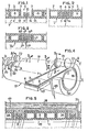
- Fig. 1 illustrates the helical winding of an extruded profile 1 made of thermoplastic plastic, for example rigid polyvinyl chloride or PVC.
- the profile 1 consists of a body 2 bordered on each side with a stapling relief 3, 4.
- the body 2 has a rectangular section with large axial sides outside 5 and inside 6 and with short radial sides 7, axial and radial extending with respect to the final tube.
- This body 2 is honeycombed or in a box, that is to say it comprises several longitudinal cavities 8 separated by partitions 9 with radial section.
- the body 2 may for example comprise four cavities 8 of rectangular section, the partitions 9 and the sides of the body having a common thickness.
- the relief 3 is a male relief. It has an L-shaped section consisting of an axial branch or web 10 and a radial branch 11.
- the first branch extends the long inner side 6 of the body 2, with the same thickness, while the second extends radially towards the outside on about half the height of a small side 7 to end in a dovetail 12.
- the relief 4 is a female relief and is made up, in section, of a part or veil 13 of connection with the body 2 which is analogous to the branch 10, located in the extension of this branch and in abutment on it in the position stapled shown. From the end of this part 13 leaves a U-shaped hook 14 outwards which turns its dovetail cavity radially inwards and which is suitable for exactly wrapping the branch 11 of the relief 3 until it comes practically into contact with the branch 10.
- the height of the assembly of the two reliefs is significantly less than that of the body 2, and its width is significantly less than the axial distance separating the short sides 7 opposite.
- the height of the assembly of the two reliefs is significantly less than that of the body 2, and its width is significantly less than the axial distance separating the short sides 7 opposite.
- the resulting tube T is therefore smooth both externally and internally, therefore insensitive to snagging or tearing during handling; in addition, the external surface of the tube can remain constantly clean because it is smooth, in particular when this tube is placed on a ground of soil and / or gravel, and the tube lends itself to assemblies by means of fittings and conventional seals. The aesthetic advantage is not negligible either.
- the winding of the profile 1 as well as the establishment of the cord 16 is preferably carried out at a temperature sufficient to ensure, in addition to their mechanical connection, a sealed connection by heat sealing of the elements 3, 4 and 16.
- glue can be used for the same purpose.
- the tube T ° of FIG. 3 does not differ from that of FIG. 2 only by the shape of the reliefs 3 ° and 4 °: the radial branch 11 of the male relief 3 ° ends in a bead 12 ° in three-quarters of a circle, and the hook 14 ° of the female relief 4 ° is rounded so conjugate.
- the concavity of the 16 ° cord is rounded correspondingly.
- Figs. 4 to 11 show a machine 17 capable of continuously producing the tube T of FIG. 2, with heat-sealing of the reliefs 3, 4 and of the cord 16.
- the modifications of this machine which are necessary to obtain the tube T ° of FIG. 3 will be obvious to those skilled in the art.
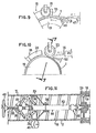
- the machine 17 essentially comprises a fixed cylindrical cage or sleeve 18 of horizontal axis XX, a coaxial mandrel 19 driven in rotation at constant speed in the direction f inside this cage, by a motor not shown, taking care with it an annular space 20, and two idler rollers 21 and 22 for guiding.
- the cage 18 At its upstream end, the cage 18 has a notch or window 23 for the entry of the profile 1 in which the roller 21 is located. Near its downstream end, but at a certain distance from the latter, the cage has a second notch or window 24, smaller than the first, for the entry of the cord 16, in which the roller 22 is located.
- the profile 1 is brought tangentially to the mandrel 19, in the window 23 and under the roller 21, at a certain angle, equal to the helix angle of the winding, relative to the axis X-X. It is delivered at constant speed by an extruder not shown or from a supply coil. Likewise, the cord 16 comes out, at constant speed, from an extruder 25 or from a supply coil to reach tangentially, in the window 24 and under the roller 22, the already wound profile.
- the cage 18 (Fig. 8) has internally over its entire length a smooth cylindrical surface partially furnished with a helical relief. This consists of upstream downstream of three successive zones: a zone 26 devoid of any relief; a zone 27 starting near the downstream end of the window 23 and ending at the upstream end of the window 24 and in which protrudes towards the axis XX a helical guide rib 28 having a U-shaped section corresponding to that cord 16 and extending over approximately two turns; and a zone 29 again devoid of any relief, the part of the cage 18 located downstream of the second window 24 extending over approximately one revolution.
- the mandrel 19 has, over its entire length, a cylindrical, striated outer surface. longitudinally to improve the drive of the profile 1. However, in line with zone 29, this surface converges slightly downstream to facilitate the exit of the tube T produced.
- the mandrel 19 is extended beyond the downstream end of the cage by a device 30 for extracting and guiding the tube T (FIG. 11).
- the downstream end of the mandrel 19 is secured in rotation and in axial translation with the driving element of a universal joint 31.
- the two driving and driven elements of the joint 31 are capable of rotating around the axis. XX with a slight angular deviation in order to give flexibility in guiding the tube T at the outlet of the cage 18.
- the driven element of the universal joint 31 is integral with a shaft 32 on which a sleeve or ring is fixed cylindrical 33 for support and internal guide of the tube T.
- the sleeve 33 rotates with the shaft 32 by virtue of a connection constituted for example by a spindle which runs right through the shaft 32 and a hub 34 of the sleeve 33.
- the shaft 32 is also provided with an expander 35 with rollers 36 of axes orthogonal to the axis of the shaft 32, for example two in number diametrically opposed, carried by levers 37 articulated in their middle and intended to separate the rollers 36 (position in solid lines) or to bring them closer (position in broken lines) to the axis XX, and consequently to press these rollers more or less on the internal wall of the tube T.
- the spacing of these rollers 36 is adjusted by means of a nut 38 on which the downstream ends of the levers 37 are articulated.
- the nut 38 is screwed onto a screw 39 operated by a handwheel 40 and extending the shaft 32, on the end of which the upstream ends of the levers 37 are articulated.
- Oblique rollers 41 of the external support are finally provided in line with the sleeve 33.
- the angle of the rollers 41 relative to the axis XX corresponds at the helix angle of the winding.
- the roller 21 for guiding the profile 1 (FIG. 6) of axis Y-Y perpendicular to the oblique arrival of the profile 1, has a profile roughly combined with the outside profile of the latter. It thus has a cylindrical part corresponding to the honeycombed body 2 and providing a slight radial clearance therewith, an upstream end cheek 42 being introduced without play into the space provided between the male relief 3 and the body 3 and, at the other end, a pair of identical cheeks 43 separated by a circular groove 44 receiving without play the female clip 14 of the profile 1. The free downstream edge of the relief 4 then is flush with the edge of the downstream cheek 43.
- the roller 22 for guiding the cord 16 (FIG. 7) with an axis ZZ oblique to the axis XX and perpendicular to the oblique arrival of this cord, comprises a pair of identical cheeks 45 delimiting between them a circular groove 46 into which the cord 16 fits without play, the branches of the latter then being flush with the edge of the cheeks 45.
- the mandrel 19 is rotated at a speed which is harmonized with the exit speed of the extruder, not shown, producing the section 1 according to arrow g (Fig. 4).
- the means, indicated above, for measuring the deflection of the loop B formed by the section 1 between its extruder outlet and the cage 18 (Fig. 9) are also used to adjust the relative speeds: when the deflection increases ( excess of the extrusion speeds relative to the winding speed), the extrusion speed is reduced (or the speed of rotation of the mandrel 19 is increased); conversely, when the deflection decreases (excess winding speed relative to the extrusion speed), the extrusion speed is increased (or the speed of rotation of the mandrel 19 is reduced).
- This regulation is carried out automatically by known means, not shown.
- the profile 1 is manually introduced under the roller 21 and into the cage 18. Then this profile continues its movement by itself, driven by the rotation of the mandrel 19 on which it is applied by the roller 21
- the entry of the profile 1 into the cage takes place tangentially to this cage and to the mandrel, through the window 23, and obliquely with respect to the axis XX, with an inclination which is that of the winding propeller.
- the male relief 3 is preferably located upstream, so that the female relief 4 first enters the closed area 27 of the cage 18.
- the profile 1 is guided by the roller 21, which rolls freely on it as on a rail, its cheek 42 positioning the male clip 3 and its cheeks 43 as well as its groove 44 positioning its female clip 4.
- the roller 21 applies the areas of contact of the profile by its cheeks 42 and 43 and its groove 44, so as to facilitate the drive of the profile by the mandrel while guiding the profile.
- the section 1 comes exactly into engagement with the helical rib 28 and its body 2 comes to fit into the space separating the turns of this rib.
- the profile and the cage engage like a screw (profile) in a nut (cage 18). As the cage is fixed, the profile 1 progresses in rotation and in translation in a helical movement.
- the first formed whorl reaches the notch 24 and enters the zone 29 of the cage 18, with a smooth wall devoid of helical rib.
- the primer of the cord 16 is introduced manually into the groove 46 of the roller 22 and into the space 15 surrounding the first turn of the stapling 3-4, this introduction taking place tangentially with respect to the mandrel 19 and obliquely with respect to axis XX, with an inclination which is that of the winding propeller.
- the cord 16, driven by the mandrel is housed at the bottom of the groove 46 and comes, at the end of the window 24, to be introduced into the helical groove 15 by covering the stapling 3-4.
- the cheeks 45 of the roller 22 roll on the edges opposite the adjacent turns of the body 2.
- the cord 16 comes to completely occupy this groove 15 by being flush the outer wall 5 of the adjacent turns. It is the cage 18 which locks the cord 16 on the stapling 3-4 and it is the absence of internal helical relief in the zone 29 of the cage which allows the introduction of the cord 16 into the cage.
- the flow rate of the extruder 25 is automatically adjusted as a function of the speed of rotation of the mandrel 19.
- this tube is still supported and driven in positive rotation by the extraction device 30, its translation being effected by the screw-nut movement formed by the groove helical 15 separating the coiled turns of the profile 1 and the helical rib 28 of the cage.
- the tube T is supported, at a certain distance beyond the cage 18, by the sleeve 33 and the rollers 41.
- the sleeve 33 integral in rotation with the mandrel 19 by means of the universal joint 31, does not offers no friction resistance to the rotation of the tube T.
- the tube T is itself positively rotated by the expander 35, the rollers 36 of which are suitably applied to the inner wall of the tube T by appropriate adjustment of the nut 38 by means of the handwheel 40.
- the oblique arrangement of the rollers 36 also allows the helical movement of the tube T.
- the tube T can be cut downstream.
Landscapes
- Engineering & Computer Science (AREA)
- Mechanical Engineering (AREA)
- Shaping Of Tube Ends By Bending Or Straightening (AREA)
- Extrusion Moulding Of Plastics Or The Like (AREA)
Applications Claiming Priority (2)
| Application Number | Priority Date | Filing Date | Title |
|---|---|---|---|
| FR7923794A FR2465581A1 (fr) | 1979-09-25 | 1979-09-25 | Machine de fabrication en continu de tubes en matiere plastique par enroulement helicoidal |
| FR7923794 | 1979-09-25 |
Publications (2)
| Publication Number | Publication Date |
|---|---|
| EP0025971A1 EP0025971A1 (fr) | 1981-04-01 |
| EP0025971B1 true EP0025971B1 (fr) | 1983-05-04 |
Family
ID=9229974
Family Applications (1)
| Application Number | Title | Priority Date | Filing Date |
|---|---|---|---|
| EP80105563A Expired EP0025971B1 (fr) | 1979-09-25 | 1980-09-17 | Machine de fabrication en continu de tubes en matière plastique par enroulement hélicoidal |
Country Status (3)
| Country | Link |
|---|---|
| EP (1) | EP0025971B1 (OSRAM) |
| DE (1) | DE3062974D1 (OSRAM) |
| FR (1) | FR2465581A1 (OSRAM) |
Cited By (3)
| Publication number | Priority date | Publication date | Assignee | Title |
|---|---|---|---|---|
| WO2005106315A1 (en) * | 2004-04-30 | 2005-11-10 | Gemma Corporation Pty Ltd | Manufacture of flexible tubular duct with improved core delivery |
| WO2005106308A1 (en) * | 2004-04-30 | 2005-11-10 | Gemma Corporation Pty Ltd | Manufacture of reinforced tubular products of predetermined length |
| CN108000858A (zh) * | 2017-12-12 | 2018-05-08 | 安徽蕴通管业科技有限公司 | 一种hdpe缠绕管生产设备 |
Families Citing this family (9)
| Publication number | Priority date | Publication date | Assignee | Title |
|---|---|---|---|---|
| CA1282571C (en) * | 1986-07-03 | 1991-04-09 | Stanley William Otto Menzel | Method of and means for producing reinforced ribbed structures |
| AU598625B2 (en) * | 1986-11-26 | 1990-06-28 | Danby Pty Ltd | Method of and machine for winding tubes from strip |
| DE3931613C1 (OSRAM) * | 1989-09-22 | 1990-09-20 | Petzetakis, George Aristovoulos, Piraeus, Gr | |
| AU2005238550C1 (en) * | 2004-04-30 | 2014-03-06 | Nova-Duct Technologies Pty Ltd | Manufacture of reinforced tubular products of predetermined length |
| CN106764126B (zh) * | 2017-01-25 | 2019-03-29 | 高其容 | 一种hdpe中空壁缠绕排水管生产设备及方法 |
| CN110001040A (zh) * | 2019-05-08 | 2019-07-12 | 杭州越歌科技有限公司 | 一种缠绕结构壁管及其制造装置 |
| CN113002033B (zh) * | 2021-03-10 | 2022-01-11 | 海宁亚大塑料管道系统有限公司 | 一种抗压型缠绕管及其生产装置与工艺 |
| CN116753394B (zh) * | 2023-08-22 | 2023-10-31 | 江西强发科技有限公司 | 一种缠绕管道修复装置 |
| CN117301488A (zh) * | 2023-09-21 | 2023-12-29 | 江西爱森德实业有限公司 | 一种聚乙烯缠绕结构壁管及其缠绕成型方法 |
-
1979
- 1979-09-25 FR FR7923794A patent/FR2465581A1/fr active Granted
-
1980
- 1980-09-17 DE DE8080105563T patent/DE3062974D1/de not_active Expired
- 1980-09-17 EP EP80105563A patent/EP0025971B1/fr not_active Expired
Non-Patent Citations (1)
| Title |
|---|
| Néant * |
Cited By (4)
| Publication number | Priority date | Publication date | Assignee | Title |
|---|---|---|---|---|
| WO2005106315A1 (en) * | 2004-04-30 | 2005-11-10 | Gemma Corporation Pty Ltd | Manufacture of flexible tubular duct with improved core delivery |
| WO2005106308A1 (en) * | 2004-04-30 | 2005-11-10 | Gemma Corporation Pty Ltd | Manufacture of reinforced tubular products of predetermined length |
| CN108000858A (zh) * | 2017-12-12 | 2018-05-08 | 安徽蕴通管业科技有限公司 | 一种hdpe缠绕管生产设备 |
| CN108000858B (zh) * | 2017-12-12 | 2020-05-19 | 安徽蕴通管业科技有限公司 | 一种hdpe缠绕管生产设备 |
Also Published As
| Publication number | Publication date |
|---|---|
| FR2465581B1 (OSRAM) | 1981-10-02 |
| DE3062974D1 (en) | 1983-06-09 |
| FR2465581A1 (fr) | 1981-03-27 |
| EP0025971A1 (fr) | 1981-04-01 |
Similar Documents
| Publication | Publication Date | Title |
|---|---|---|
| EP0025971B1 (fr) | Machine de fabrication en continu de tubes en matière plastique par enroulement hélicoidal | |
| CA2297763C (fr) | Conduit flexible, par exemple tuyau a usage medical ou chirurgical | |
| EP0025121B1 (fr) | Tube en matière plastique obtenu par enroulement en hélice d'un profilé | |
| EP3458767A1 (fr) | Reservoir en matériau composite pour contenir un fluide sous pression | |
| WO2014118480A1 (fr) | Procédé de fabrication amélioré d'un arbre de transmission, de préférence pour système de boîte d'accessoires de turbomachine d'aéronef | |
| EP0036381B1 (fr) | Procédé de formage de profilés, notamment de profilés tubulaires | |
| EP1467852B1 (fr) | PROCEDE DE FABRICATION PAR CENTRIFUGATION DE VIROLES A DOUBLE PAROI. | |
| BE623129A (OSRAM) | ||
| EP0310499A1 (fr) | Procédé et dispositif pour la fabrication d'une structure tubulaire fibreuse stratifiée utilisable comme structure de renfort pour pièce composite | |
| EP0402199B1 (fr) | Procédé de fabrication de manchon électro-soudable, dispositif pour la mise en oeuvre de celui-ci et manchons obtenus selon ce procédé | |
| EP1519826A1 (fr) | Procede et dispositif de fabrication d'un corps de revolution et produits obtenus | |
| BE1008956A3 (fr) | Procede de fabrication d'un tuyau a base de matiere plastique, filiere d'extrusion et tuyau. | |
| WO2000006852A1 (fr) | Gaine de cable amelioree | |
| FR2735511A1 (fr) | Gaine de cable a structure multi-couche, son procede de fabrication et machine pour mettre en oeuvre ce procede | |
| FR2893111A1 (fr) | Boitier pour joints, de preference pour joints radiaux d'arbres, et procede pour sa fabrication | |
| FR2588352A1 (fr) | Tuyau en beton a chemisage interne en matiere plastique et procede de realisation d'un tel tuyau | |
| EP0202983B1 (fr) | Procédé et machine de fabrication d'une isolation thermique multicouche autour et le long d'une traversée solide, et resérvoir cryogénique correspondant | |
| CH206768A (fr) | Procédé de fabrication d'un tuyau flexible, installation pour sa mise en oeuvre, et tuyau flexible obtenu au moyen de ce procédé. | |
| BE1004786A3 (fr) | Appareil pour fabriquer un tube ondule. | |
| EP1574319B1 (fr) | Procédé d'enroulement d'un ruban composite et son dispositif de mise en oeuvre | |
| EP1341662B1 (fr) | Methode et appareil pour generer des spirales en plastique | |
| BE516916A (OSRAM) | ||
| FR2710872A3 (fr) | Procédé d'obtention des tubes en carton avec revêtement interne étanche, notamment de coffrages, et dispositifs de mise en Óoeuvre. | |
| FR2616087A1 (fr) | Methode et dispositif pour l'encollage d'un element profile | |
| BE680627A (OSRAM) |
Legal Events
| Date | Code | Title | Description |
|---|---|---|---|
| PUAI | Public reference made under article 153(3) epc to a published international application that has entered the european phase |
Free format text: ORIGINAL CODE: 0009012 |
|
| AK | Designated contracting states |
Designated state(s): BE CH DE GB IT LU NL SE |
|
| 17P | Request for examination filed |
Effective date: 19810410 |
|
| ITF | It: translation for a ep patent filed | ||
| GRAA | (expected) grant |
Free format text: ORIGINAL CODE: 0009210 |
|
| AK | Designated contracting states |
Designated state(s): BE CH DE GB IT LI LU NL SE |
|
| REF | Corresponds to: |
Ref document number: 3062974 Country of ref document: DE Date of ref document: 19830609 |
|
| PGFP | Annual fee paid to national office [announced via postgrant information from national office to epo] |
Ref country code: LU Payment date: 19830907 Year of fee payment: 4 |
|
| PG25 | Lapsed in a contracting state [announced via postgrant information from national office to epo] |
Ref country code: LU Free format text: LAPSE BECAUSE OF NON-PAYMENT OF DUE FEES Effective date: 19830930 |
|
| PLBE | No opposition filed within time limit |
Free format text: ORIGINAL CODE: 0009261 |
|
| STAA | Information on the status of an ep patent application or granted ep patent |
Free format text: STATUS: NO OPPOSITION FILED WITHIN TIME LIMIT |
|
| 26N | No opposition filed | ||
| PGFP | Annual fee paid to national office [announced via postgrant information from national office to epo] |
Ref country code: CH Payment date: 19840910 Year of fee payment: 5 |
|
| PGFP | Annual fee paid to national office [announced via postgrant information from national office to epo] |
Ref country code: SE Payment date: 19840930 Year of fee payment: 5 Ref country code: NL Payment date: 19840930 Year of fee payment: 5 Ref country code: BE Payment date: 19840930 Year of fee payment: 5 |
|
| PGFP | Annual fee paid to national office [announced via postgrant information from national office to epo] |
Ref country code: DE Payment date: 19841017 Year of fee payment: 5 |
|
| PG25 | Lapsed in a contracting state [announced via postgrant information from national office to epo] |
Ref country code: SE Effective date: 19850918 |
|
| PG25 | Lapsed in a contracting state [announced via postgrant information from national office to epo] |
Ref country code: LI Effective date: 19850930 Ref country code: CH Effective date: 19850930 Ref country code: BE Effective date: 19850930 |
|
| BERE | Be: lapsed |
Owner name: PONT-A-MOUSSON S.A. Effective date: 19850917 |
|
| PG25 | Lapsed in a contracting state [announced via postgrant information from national office to epo] |
Ref country code: NL Effective date: 19860401 |
|
| GBPC | Gb: european patent ceased through non-payment of renewal fee | ||
| NLV4 | Nl: lapsed or anulled due to non-payment of the annual fee | ||
| REG | Reference to a national code |
Ref country code: CH Ref legal event code: PL |
|
| PG25 | Lapsed in a contracting state [announced via postgrant information from national office to epo] |
Ref country code: DE Effective date: 19860603 |
|
| PG25 | Lapsed in a contracting state [announced via postgrant information from national office to epo] |
Ref country code: GB Effective date: 19881118 |
|
| EUG | Se: european patent has lapsed |
Ref document number: 80105563.3 Effective date: 19860729 |