EP0025792B1 - Insulated tank container - Google Patents
Insulated tank container Download PDFInfo
- Publication number
- EP0025792B1 EP0025792B1 EP80900564A EP80900564A EP0025792B1 EP 0025792 B1 EP0025792 B1 EP 0025792B1 EP 80900564 A EP80900564 A EP 80900564A EP 80900564 A EP80900564 A EP 80900564A EP 0025792 B1 EP0025792 B1 EP 0025792B1
- Authority
- EP
- European Patent Office
- Prior art keywords
- tank container
- insulation
- glued
- shell
- tanks
- Prior art date
- Legal status (The legal status is an assumption and is not a legal conclusion. Google has not performed a legal analysis and makes no representation as to the accuracy of the status listed.)
- Expired
Links
Images

Classifications
-
- B—PERFORMING OPERATIONS; TRANSPORTING
- B65—CONVEYING; PACKING; STORING; HANDLING THIN OR FILAMENTARY MATERIAL
- B65D—CONTAINERS FOR STORAGE OR TRANSPORT OF ARTICLES OR MATERIALS, e.g. BAGS, BARRELS, BOTTLES, BOXES, CANS, CARTONS, CRATES, DRUMS, JARS, TANKS, HOPPERS, FORWARDING CONTAINERS; ACCESSORIES, CLOSURES, OR FITTINGS THEREFOR; PACKAGING ELEMENTS; PACKAGES
- B65D88/00—Large containers
- B65D88/02—Large containers rigid
- B65D88/12—Large containers rigid specially adapted for transport
- B65D88/128—Large containers rigid specially adapted for transport tank containers, i.e. containers provided with supporting devices for handling
-
- B—PERFORMING OPERATIONS; TRANSPORTING
- B65—CONVEYING; PACKING; STORING; HANDLING THIN OR FILAMENTARY MATERIAL
- B65D—CONTAINERS FOR STORAGE OR TRANSPORT OF ARTICLES OR MATERIALS, e.g. BAGS, BARRELS, BOTTLES, BOXES, CANS, CARTONS, CRATES, DRUMS, JARS, TANKS, HOPPERS, FORWARDING CONTAINERS; ACCESSORIES, CLOSURES, OR FITTINGS THEREFOR; PACKAGING ELEMENTS; PACKAGES
- B65D90/00—Component parts, details or accessories for large containers
- B65D90/02—Wall construction
- B65D90/06—Coverings, e.g. for insulating purposes
-
- Y—GENERAL TAGGING OF NEW TECHNOLOGICAL DEVELOPMENTS; GENERAL TAGGING OF CROSS-SECTIONAL TECHNOLOGIES SPANNING OVER SEVERAL SECTIONS OF THE IPC; TECHNICAL SUBJECTS COVERED BY FORMER USPC CROSS-REFERENCE ART COLLECTIONS [XRACs] AND DIGESTS
- Y10—TECHNICAL SUBJECTS COVERED BY FORMER USPC
- Y10S—TECHNICAL SUBJECTS COVERED BY FORMER USPC CROSS-REFERENCE ART COLLECTIONS [XRACs] AND DIGESTS
- Y10S220/00—Receptacles
- Y10S220/901—Liquified gas content, cryogenic
-
- Y—GENERAL TAGGING OF NEW TECHNOLOGICAL DEVELOPMENTS; GENERAL TAGGING OF CROSS-SECTIONAL TECHNOLOGIES SPANNING OVER SEVERAL SECTIONS OF THE IPC; TECHNICAL SUBJECTS COVERED BY FORMER USPC CROSS-REFERENCE ART COLLECTIONS [XRACs] AND DIGESTS
- Y10—TECHNICAL SUBJECTS COVERED BY FORMER USPC
- Y10S—TECHNICAL SUBJECTS COVERED BY FORMER USPC CROSS-REFERENCE ART COLLECTIONS [XRACs] AND DIGESTS
- Y10S220/00—Receptacles
- Y10S220/902—Foam
Definitions
- the present invention relates to an insulated tank container, preferably but not exclusively of the type which comprises a framework and which can be transferred between different vehicles etc. It comprises an inner shell surrounded by a layer of insulation, which is firmly glued or otherwise integrated with the shell and with rigid end frames of the tank container.
- Conventional insulated tank containers have normally such a thick inner body plate that this carries the stresses of the load and any internal excess pressure.
- the tank or container is self-supporting and the insulation situated on the outside (with a protective outer skin) has, in principle, no other function than just to insulate.
- the tank normally rests on its chassis through rigid brackets or so-called saddles.
- cryotanks there is also the possibility, according to the standards, of including an outer shell to take up the load, but these tanks are spherical because of the pressure, so that the only additional purpose of the insulation is to hold the shells apart.
- a conventional tank container is therefore both heavy and expensive.
- the inner shell comprises a plurality of tanks with outwardly bent or curved walls and substantially rectangular cross-section and that the insulation layer is such that it also performs the main load-bearing function in use.
- the tank walls are exposed by the liquid to forces which are transferred to the insulation in the form of compressive stresses, shear stresses and sometimes moderate tensile stresses, all of which can be taken up and transferred by the semi-hard or hard insulation.
- the insulation may have a protective layer on the outside.
- an outer shell is firmly glued to or otherwise integrated with the insulation, the outer shell preferably comprising protective rigid corner strips.
- the insulation may consist of preformed, preferably disc-shaped parts glued to the inner and the outer shell.
- the inner shell preferably consists of a plurality of preformed tanks of a material which is suitable in view of the contents, while the outer shell is built up of rigid corner strips and discs of a material without any demands for resistance to the contents of the container, and the preferably disc-shaped insulating parts are glued to said discs before mounting and are glued to the tanks during the mounting.
- the various disc-shaped insulating parts and the outer shell After the mounting of the inner shell, the various disc-shaped insulating parts and the outer shell, certain remaining, unfilled spaces remain between the shells. These can be filled with injected insulating material in foamed form, which hardens in situ.
- An alternative method of production is to introduce (inject) foam and harden all the insulating material in situ between preformed shells.
- the inner shell is very thin and therefore lacks the necessary carrying capacity, there may be some kind of contour-retaining elements in the inner shell during manufacture, which are later removed.
- the necessary pipes, valves, etc. are mainly disposed in the insulation so that the tank container has a smooth exterior which is an advantage from several points of view.
- FIG. 1 illustrate typical steps in the coming into existence of a tank container according to the invention
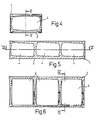
- Figs. 4-6 show, on a smaller scale, three sections through the finished tank container (along the lines IV-IV of Fig. 6, V-V of Fig. 4 and VI-VI of Fig. 5 respectively.
- Fig. 1 shows an assembled tank container frame 1, which preferably consists of a plurality of rigid corner strips welded together, for example of aluminium with a typical thickness of 4 mm.
- Such a frame for a so-called half-high 20' container has a frame weight of about 280 kg.
- This frame 1 is placed on a bottom covering plate 2, to which there are glued substantially disc-shaped bottom insulating parts 3 with suitable recesses for emptying pipes and valves only indicated in Fig. 6.
- the parts 3 like all the insulating parts described below, are made of a semi-hard or hard insulating material with the capacity to take up and transfer stresses in various directions, for example foam plastics of the Divinylcelle type.
- the bottom covering plate 2, like all the covering plates described below, can be made of aluminium with a thickness of 1.25 mm for example.
- Fig. 2 illustrates the introduction of three inner tanks 4 of a material which is resistant to the intended contents of the tank or which is selected to meet the hygiene demands.
- the three tanks are made of stainless plate t.25 mm thick and then have a total weight of 540 kg.
- FIG. 3 illustrates the application of the remaining parts to the tank container: side covering plates 5 with glued-on side insulating parts 6, end covering plates 7 with glued-on end insulating parts 8, an upper covering plate 9 with glued-on upper insulating parts 10 and insulating partitions 11 between adjacent tanks.
- the total weight of the covering plates is about 140 kg and of the insulation (Divinycell @ with a density of 60 kg/m 3 at the bottom and 45 kg/m 3 otherwise) about 160 kg.
- the total weight of the tank container shown (including certain other equipment not shown) is about 1200 kg, which may be compared with the weight of 2400 kg for a corresponding conventionally insulated tank container. In both cases the volume of the container is about 14.5 m 3 .
- the whole construction may appropriately be placed in a "bag" from which the air is sucked out, while at the same time the interior of the tanks 4 is heated up. As a result vacuum adhesion is brought about.
- any residual spaces can be filled with injected foam plastics which hardens in situ.
- the embodiment described is merely an example of various possibilities.
- the outer shell and the insulation together as an integrated unit can give the necessary stability and load-bearing capacity.
- the insulation should have some kind of protective outer layer.
- insulation can be injected, foamed and hardened in situ between preformed shells.
- contour-maintaining elements may be inserted in the tanks during production and thereafter removed.
Landscapes
- Engineering & Computer Science (AREA)
- Mechanical Engineering (AREA)
- Filling Or Discharging Of Gas Storage Vessels (AREA)
- Physical Water Treatments (AREA)
- Thermal Insulation (AREA)
Abstract
Description
- The present invention relates to an insulated tank container, preferably but not exclusively of the type which comprises a framework and which can be transferred between different vehicles etc. It comprises an inner shell surrounded by a layer of insulation, which is firmly glued or otherwise integrated with the shell and with rigid end frames of the tank container.
- Conventional insulated tank containers have normally such a thick inner body plate that this carries the stresses of the load and any internal excess pressure. In other words, the tank or container is self-supporting and the insulation situated on the outside (with a protective outer skin) has, in principle, no other function than just to insulate. The tank normally rests on its chassis through rigid brackets or so-called saddles.
- In some cases, according to current standards, certain external loads are permitted on the insulation. The thickness of the body can thus be reduced somewhat, if blows and shocks from the outside can be damped by the insulation.
- For so-called cryotanks, there is also the possibility, according to the standards, of including an outer shell to take up the load, but these tanks are spherical because of the pressure, so that the only additional purpose of the insulation is to hold the shells apart.
- A conventional tank container is therefore both heavy and expensive.
- Examples of prior designs with certain drawbacks obviated by the present invention are given in US - A - 3 115 982 and DE-A-2 101 075 but also in DE-A-2 541 375.
- In the design according to US - A - 3 115 982 (shown as an insulated freight car) inner and outer shells are unloaded relative tc each other, so that the container can withstand high temperature differences. The outer framework is completely self-supporting, whereas the inner parts of the container have the only purpose of insulating and withstanding thermal forces, which are unloaded in a complex way.
- In the design shown in DE - A - 2 101 075 both the insulation and the framework carry load, whereas a loose tank inside the container is adapted for the material to be transported. Sophisticated temperature-breaking and force- transmitting bridges are required.
- A considerably improved, lighter and cheaper construction is achieved by the invention, according to which the inner shell comprises a plurality of tanks with outwardly bent or curved walls and substantially rectangular cross-section and that the insulation layer is such that it also performs the main load-bearing function in use.
- The tank walls are exposed by the liquid to forces which are transferred to the insulation in the form of compressive stresses, shear stresses and sometimes moderate tensile stresses, all of which can be taken up and transferred by the semi-hard or hard insulation.
- Thus, together, the inner shell and the insulation form a load-bearing unit. The insulation may have a protective layer on the outside.
- Another and preferred embodiment is that an outer shell is firmly glued to or otherwise integrated with the insulation, the outer shell preferably comprising protective rigid corner strips.
- The insulation may consist of preformed, preferably disc-shaped parts glued to the inner and the outer shell.
- The inner shell preferably consists of a plurality of preformed tanks of a material which is suitable in view of the contents, while the outer shell is built up of rigid corner strips and discs of a material without any demands for resistance to the contents of the container, and the preferably disc-shaped insulating parts are glued to said discs before mounting and are glued to the tanks during the mounting.
- After the mounting of the inner shell, the various disc-shaped insulating parts and the outer shell, certain remaining, unfilled spaces remain between the shells. These can be filled with injected insulating material in foamed form, which hardens in situ.
- An alternative method of production is to introduce (inject) foam and harden all the insulating material in situ between preformed shells.
- Particularly if the inner shell is very thin and therefore lacks the necessary carrying capacity, there may be some kind of contour-retaining elements in the inner shell during manufacture, which are later removed.
- The necessary pipes, valves, etc. are mainly disposed in the insulation so that the tank container has a smooth exterior which is an advantage from several points of view.
- The invention will be described in more detail below with reference to the accompanying drawings in which Figs. 1-3 illustrate typical steps in the coming into existence of a tank container according to the invention and Figs. 4-6 show, on a smaller scale, three sections through the finished tank container (along the lines IV-IV of Fig. 6, V-V of Fig. 4 and VI-VI of Fig. 5 respectively.
- Fig. 1 shows an assembled
tank container frame 1, which preferably consists of a plurality of rigid corner strips welded together, for example of aluminium with a typical thickness of 4 mm. Such a frame for a so-called half-high 20' container has a frame weight of about 280 kg. - This
frame 1 is placed on abottom covering plate 2, to which there are glued substantially disc-shapedbottom insulating parts 3 with suitable recesses for emptying pipes and valves only indicated in Fig. 6. - These
parts 3, like all the insulating parts described below, are made of a semi-hard or hard insulating material with the capacity to take up and transfer stresses in various directions, for example foam plastics of the Divinylcelle type. Thebottom covering plate 2, like all the covering plates described below, can be made of aluminium with a thickness of 1.25 mm for example. - Fig. 2 illustrates the introduction of three
inner tanks 4 of a material which is resistant to the intended contents of the tank or which is selected to meet the hygiene demands. On the other hand, in principle, there are no demands on the carrying capacity of the tanks. In the present case, the three tanks are made of stainless plate t.25 mm thick and then have a total weight of 540 kg. - Fig. 3 illustrates the application of the remaining parts to the tank container:
side covering plates 5 with glued-on sideinsulating parts 6,end covering plates 7 with glued-on endinsulating parts 8, an upper covering plate 9 with glued-on upperinsulating parts 10 andinsulating partitions 11 between adjacent tanks. - With the embodiment illustrated and described, the total weight of the covering plates is about 140 kg and of the insulation (Divinycell@ with a density of 60 kg/m3 at the bottom and 45 kg/m3 otherwise) about 160 kg.
- The total weight of the tank container shown (including certain other equipment not shown) is about 1200 kg, which may be compared with the weight of 2400 kg for a corresponding conventionally insulated tank container. In both cases the volume of the container is about 14.5 m3.
- After suitable adhesive has been supplied to all the surfaces which are to be glued in the construction, that is to say, in principle, all the free surfaces before the assembly described above with reference to Figs. 1-3, the whole construction may appropriately be placed in a "bag" from which the air is sucked out, while at the same time the interior of the
tanks 4 is heated up. As a result vacuum adhesion is brought about. - When the glueing operation is finished, any residual spaces can be filled with injected foam plastics which hardens in situ.
- In Figs. 4-6 the reference numerals for the various insulating parts have been omitted for the sake of clarity; all the hatched surfaces consist of insulation.
- It should be observed that the embodiment described is merely an example of various possibilities. In particular, it should be noted that the outer shell and the insulation together as an integrated unit can give the necessary stability and load-bearing capacity. In such a case, the insulation should have some kind of protective outer layer.
- Another important modification is that the insulation can be injected, foamed and hardened in situ between preformed shells.
- Particularly if the tanks are very thin, contour-maintaining elements may be inserted in the tanks during production and thereafter removed.
Claims (8)
Priority Applications (1)
| Application Number | Priority Date | Filing Date | Title |
|---|---|---|---|
| AT80900564T ATE4186T1 (en) | 1979-03-28 | 1980-03-26 | INSULATED TANK. |
Applications Claiming Priority (2)
| Application Number | Priority Date | Filing Date | Title |
|---|---|---|---|
| SE7902762 | 1979-03-28 | ||
| SE7902762A SE421299B (en) | 1979-03-28 | 1979-03-28 | ISOLATED TANK CONTAINER |
Publications (2)
| Publication Number | Publication Date |
|---|---|
| EP0025792A1 EP0025792A1 (en) | 1981-04-01 |
| EP0025792B1 true EP0025792B1 (en) | 1983-07-20 |
Family
ID=20337666
Family Applications (1)
| Application Number | Title | Priority Date | Filing Date |
|---|---|---|---|
| EP80900564A Expired EP0025792B1 (en) | 1979-03-28 | 1980-10-08 | Insulated tank container |
Country Status (8)
| Country | Link |
|---|---|
| US (1) | US4376494A (en) |
| EP (1) | EP0025792B1 (en) |
| JP (1) | JPS56500306A (en) |
| AT (1) | ATE4186T1 (en) |
| BR (1) | BR8007956A (en) |
| DE (1) | DE3064194D1 (en) |
| SE (1) | SE421299B (en) |
| WO (1) | WO1980002019A1 (en) |
Cited By (3)
| Publication number | Priority date | Publication date | Assignee | Title |
|---|---|---|---|---|
| DE19727780A1 (en) * | 1997-06-30 | 1999-01-07 | Marcus Boehm | Insulating hood for food product transporting system |
| AT505397B1 (en) * | 2007-07-19 | 2009-01-15 | Josef Mikl | CONTAINER FOR RECEIVING A FLUID |
| WO2009010544A1 (en) | 2007-07-19 | 2009-01-22 | Josef Mikl | Tank for accommodating a fluid |
Families Citing this family (9)
| Publication number | Priority date | Publication date | Assignee | Title |
|---|---|---|---|---|
| US4445624A (en) * | 1981-05-29 | 1984-05-01 | Gill Martin S | Tanks for transporting liquids |
| SE429735B (en) * | 1981-12-10 | 1983-09-26 | Widman Jan Karl Anders | SELF-PREPARING LOADS, PICTURES ENDED, LOADS RECOVERY SPACE, REFERENCES FOR REFRIGERATOR / FREEZING TRANSPORT |
| US4533050A (en) * | 1984-02-10 | 1985-08-06 | Bake Jr Louis S | Cushioned container |
| SE456901B (en) * | 1987-02-09 | 1988-11-14 | Philips Norden Ab | FERTILIZER TREATMENT |
| FR2753181B1 (en) * | 1996-09-10 | 1998-12-04 | Calais Didier | LIQUID PRODUCTS STORAGE TANK |
| GB2322154A (en) * | 1997-02-13 | 1998-08-19 | Dennis Davy Anderson | Apparatus for insulating a water tank in a roof space |
| CN2317196Y (en) * | 1998-03-03 | 1999-05-05 | 古敦仁 | Container with buffer and anticollision function |
| US20090272666A1 (en) * | 2008-05-02 | 2009-11-05 | Marcel Eric P | Tank tote |
| US10870514B2 (en) | 2017-12-29 | 2020-12-22 | Integrated Treatment Systems, Llc | Free-standing modular frame and liner for holding liquid in a shipping container |
Family Cites Families (17)
| Publication number | Priority date | Publication date | Assignee | Title |
|---|---|---|---|---|
| DE1071575B (en) * | 1959-12-17 | Norddeutsche Seckabelwerke Aktiengesellschaft, Nordemham (Oldbg.) | Box-shaped packaging container for fruit, vegetables or the like | |
| US695618A (en) * | 1901-08-26 | 1902-03-18 | Augustus F Mack | Box. |
| US2764314A (en) * | 1952-07-16 | 1956-09-25 | Skydyne Inc | Corner construction for a receptacle |
| NL110538C (en) * | 1959-09-10 | |||
| US3115982A (en) * | 1960-03-18 | 1963-12-31 | Liquefreeze Company Inc | Insulated freight car |
| FR1294767A (en) * | 1961-03-20 | 1962-06-01 | Comp Generale Electricite | Container that can form a cabinet, cupboard, desk, locker, for all uses |
| NL135090C (en) * | 1962-03-12 | 1972-04-17 | ||
| NL148795C (en) * | 1964-07-24 | |||
| DE1501699A1 (en) * | 1966-11-26 | 1969-12-18 | Wesen Ag | Container for holding deep-frozen liquids |
| US3412521A (en) * | 1967-02-06 | 1968-11-26 | Dow Chemical Co | Method for packing articles |
| CH472325A (en) * | 1967-04-07 | 1969-05-15 | Grube Veb Kraftfahrzeug | Containers for liquids, in particular for transporting milk |
| US3435946A (en) * | 1968-02-12 | 1969-04-01 | Polymir Ind Inc | Protective shock resistant package for fragile objects |
| DE2101075A1 (en) * | 1971-01-12 | 1972-08-03 | Esso Research and Engineering Co., Linden, NJ. (V.StA.) | Vessel for storing liquefied natural gas under pressure, has inner and outer hull, hold being partly bounded by inner hull and containing independent, self supporting tank of laminated thermal insulation construction |
| FR2178752B1 (en) * | 1972-04-05 | 1976-10-29 | Gaz Transport | |
| GB1442399A (en) * | 1973-05-18 | 1976-07-14 | Marine Ind Developments Ltd | Containers for storing substances at sub-zero temperatures |
| DE2541375B2 (en) * | 1975-09-17 | 1980-03-27 | Schwelmer Eisenwerk Mueller & Co Gmbh, 5830 Schwelm | Tank container for the transport of aggressive liquids |
| DE2856442A1 (en) * | 1978-12-28 | 1980-07-17 | Schwieter Tank & Apparatebau | Container frame enclosing tank esp. transporting milk etc. - supported by filling of polyurethane foam avoiding heat bridges |
-
1979
- 1979-03-28 SE SE7902762A patent/SE421299B/en not_active IP Right Cessation
-
1980
- 1980-03-26 JP JP50066380A patent/JPS56500306A/ja active Pending
- 1980-03-26 WO PCT/SE1980/000086 patent/WO1980002019A1/en active IP Right Grant
- 1980-03-26 US US06/224,561 patent/US4376494A/en not_active Expired - Lifetime
- 1980-03-26 AT AT80900564T patent/ATE4186T1/en not_active IP Right Cessation
- 1980-03-26 BR BR8007956A patent/BR8007956A/en unknown
- 1980-03-26 DE DE8080900564T patent/DE3064194D1/en not_active Expired
- 1980-10-08 EP EP80900564A patent/EP0025792B1/en not_active Expired
Cited By (4)
| Publication number | Priority date | Publication date | Assignee | Title |
|---|---|---|---|---|
| DE19727780A1 (en) * | 1997-06-30 | 1999-01-07 | Marcus Boehm | Insulating hood for food product transporting system |
| AT505397B1 (en) * | 2007-07-19 | 2009-01-15 | Josef Mikl | CONTAINER FOR RECEIVING A FLUID |
| WO2009010544A1 (en) | 2007-07-19 | 2009-01-22 | Josef Mikl | Tank for accommodating a fluid |
| AT505660B1 (en) * | 2007-07-19 | 2009-03-15 | Josef Mikl | CONTAINER FOR RECEIVING A FLUID |
Also Published As
| Publication number | Publication date |
|---|---|
| SE421299B (en) | 1981-12-14 |
| BR8007956A (en) | 1981-03-31 |
| DE3064194D1 (en) | 1983-08-25 |
| ATE4186T1 (en) | 1983-08-15 |
| US4376494A (en) | 1983-03-15 |
| EP0025792A1 (en) | 1981-04-01 |
| WO1980002019A1 (en) | 1980-10-02 |
| JPS56500306A (en) | 1981-03-12 |
| SE7902762L (en) | 1980-09-29 |
Similar Documents
| Publication | Publication Date | Title |
|---|---|---|
| EP0025792B1 (en) | Insulated tank container | |
| US8049194B2 (en) | Container for nuclear fuel transportation | |
| JPH07500406A (en) | Preformed structures forming watertight insulating walls of cryogenic fluid-tight containers | |
| US4559274A (en) | Composite components of sandwich construction | |
| US20100288778A1 (en) | Sealed, thermally insulated tank with compression-resistant non-conducting elements | |
| JP3193107B2 (en) | Missile canister and its manufacturing method | |
| EP2022728A1 (en) | Container for the transport of temperature sensitive products | |
| US20020130131A1 (en) | Thermal container | |
| US3367492A (en) | Insulation system | |
| CN101920822A (en) | Transport container | |
| WO2009019251A1 (en) | Container for the transport of temperature sensitive products | |
| WO2016062894A1 (en) | Thermally insulated transport container comprising thermal insulation resting against the walls, and wall structure of a container of said type | |
| US2714516A (en) | Liquid transporting tanks | |
| US3303617A (en) | Cored wall construction | |
| GB2267101A (en) | Insulating board | |
| JPH05124137A (en) | Sandwich member in form of plate, dish, etc. | |
| US3003199A (en) | Refrigerator car or the like | |
| EP0440031B1 (en) | Vacuum heat-insulating container | |
| US20020074526A1 (en) | Container for nuclear fuel transportation | |
| JPS6392897A (en) | Isothermal structure | |
| EP1345744B1 (en) | Process for manufacturing multi-walled vessels | |
| JP4852986B2 (en) | Heat insulation box | |
| JPH08100991A (en) | Manufacture of thermal insulation panel | |
| JP2591977B2 (en) | Thermal insulation structure and method of manufacturing the same | |
| JP2007131320A (en) | Heat insulation box |
Legal Events
| Date | Code | Title | Description |
|---|---|---|---|
| PUAI | Public reference made under article 153(3) epc to a published international application that has entered the european phase |
Free format text: ORIGINAL CODE: 0009012 |
|
| 17P | Request for examination filed |
Effective date: 19801104 |
|
| AK | Designated contracting states |
Designated state(s): AT CH DE FR GB NL |
|
| GRAA | (expected) grant |
Free format text: ORIGINAL CODE: 0009210 |
|
| AK | Designated contracting states |
Designated state(s): AT CH DE FR GB NL |
|
| REF | Corresponds to: |
Ref document number: 4186 Country of ref document: AT Date of ref document: 19830815 Kind code of ref document: T |
|
| REF | Corresponds to: |
Ref document number: 3064194 Country of ref document: DE Date of ref document: 19830825 |
|
| ET | Fr: translation filed | ||
| PGFP | Annual fee paid to national office [announced via postgrant information from national office to epo] |
Ref country code: CH Payment date: 19840222 Year of fee payment: 5 |
|
| PGFP | Annual fee paid to national office [announced via postgrant information from national office to epo] |
Ref country code: FR Payment date: 19840402 Year of fee payment: 5 |
|
| PGFP | Annual fee paid to national office [announced via postgrant information from national office to epo] |
Ref country code: DE Payment date: 19840524 Year of fee payment: 5 |
|
| PLBE | No opposition filed within time limit |
Free format text: ORIGINAL CODE: 0009261 |
|
| STAA | Information on the status of an ep patent application or granted ep patent |
Free format text: STATUS: NO OPPOSITION FILED WITHIN TIME LIMIT |
|
| 26N | No opposition filed | ||
| PGFP | Annual fee paid to national office [announced via postgrant information from national office to epo] |
Ref country code: AT Payment date: 19870324 Year of fee payment: 8 |
|
| PGFP | Annual fee paid to national office [announced via postgrant information from national office to epo] |
Ref country code: NL Payment date: 19870331 Year of fee payment: 8 |
|
| PG25 | Lapsed in a contracting state [announced via postgrant information from national office to epo] |
Ref country code: AT Effective date: 19880326 |
|
| PG25 | Lapsed in a contracting state [announced via postgrant information from national office to epo] |
Ref country code: CH Effective date: 19880331 |
|
| PG25 | Lapsed in a contracting state [announced via postgrant information from national office to epo] |
Ref country code: NL Effective date: 19881001 |
|
| NLV4 | Nl: lapsed or anulled due to non-payment of the annual fee | ||
| PG25 | Lapsed in a contracting state [announced via postgrant information from national office to epo] |
Ref country code: GB Free format text: LAPSE BECAUSE OF NON-PAYMENT OF DUE FEES Effective date: 19881118 |
|
| GBPC | Gb: european patent ceased through non-payment of renewal fee | ||
| PG25 | Lapsed in a contracting state [announced via postgrant information from national office to epo] |
Ref country code: FR Free format text: LAPSE BECAUSE OF NON-PAYMENT OF DUE FEES Effective date: 19881130 |
|
| REG | Reference to a national code |
Ref country code: CH Ref legal event code: PL |
|
| PG25 | Lapsed in a contracting state [announced via postgrant information from national office to epo] |
Ref country code: DE Effective date: 19881201 |
|
| REG | Reference to a national code |
Ref country code: FR Ref legal event code: ST |