EP0025729B1 - Switch with several crosspoint layers - Google Patents
Switch with several crosspoint layers Download PDFInfo
- Publication number
- EP0025729B1 EP0025729B1 EP19800401188 EP80401188A EP0025729B1 EP 0025729 B1 EP0025729 B1 EP 0025729B1 EP 19800401188 EP19800401188 EP 19800401188 EP 80401188 A EP80401188 A EP 80401188A EP 0025729 B1 EP0025729 B1 EP 0025729B1
- Authority
- EP
- European Patent Office
- Prior art keywords
- plug
- bars
- switch according
- selection
- grid
- Prior art date
- Legal status (The legal status is an assumption and is not a legal conclusion. Google has not performed a legal analysis and makes no representation as to the accuracy of the status listed.)
- Expired
Links
Images


Classifications
-
- H—ELECTRICITY
- H04—ELECTRIC COMMUNICATION TECHNIQUE
- H04Q—SELECTING
- H04Q1/00—Details of selecting apparatus or arrangements
- H04Q1/02—Constructional details
- H04Q1/14—Distribution frames
- H04Q1/145—Distribution frames with switches arranged in a matrix configuration
-
- H—ELECTRICITY
- H01—ELECTRIC ELEMENTS
- H01H—ELECTRIC SWITCHES; RELAYS; SELECTORS; EMERGENCY PROTECTIVE DEVICES
- H01H67/00—Electrically-operated selector switches
- H01H67/22—Switches without multi-position wipers
- H01H67/26—Co-ordinate-type selector switches not having relays at cross-points but involving mechanical movement, e.g. cross-bar switch, code-bar switch
-
- H—ELECTRICITY
- H02—GENERATION; CONVERSION OR DISTRIBUTION OF ELECTRIC POWER
- H02B—BOARDS, SUBSTATIONS OR SWITCHING ARRANGEMENTS FOR THE SUPPLY OR DISTRIBUTION OF ELECTRIC POWER
- H02B1/00—Frameworks, boards, panels, desks, casings; Details of substations or switching arrangements
- H02B1/20—Bus-bar or other wiring layouts, e.g. in cubicles, in switchyards
- H02B1/207—Cross-bar layouts
Definitions
- the present invention relates to a matrix switch with several layers of crossing points according to the preamble of claim 1. These switches can be used in particular in telephone or other distributors, or in similar devices. More particularly, the invention relates to such a switch with selection by coordinates.
- Cross bar telephone switches have been known for a long time. Recently, multi-layer switches have been developed such as those described in patents FR-A-1,584,604 and FR-A-2,106,738. These switches consist of several first layers of parallel wires oriented in a first direction and several second layers of parallel threads interposed between the first layers and oriented in a direction perpendicular to the first layers. We thus define, in a direction normal to the plies of wires, multiple crossing points which are open or closed by sorts of multi-contact plugs displaced perpendicular to the plies. In patent FR-A-2 038 444, multi-contact plugs are also used which are rotated to close or break the contacts. These switches have been designed to constitute fast-functioning switches involved in establishing communications between subscribers.
- US-A-3,312,792 there is described a switching matrix with a layer of crossing points comprising a first layer of pairs of parallel wires, oriented in a first direction, and a second layer of pairs of parallel threads, oriented in a direction perpendicular to the first. The first and second layers are superimposed.
- plugs which can turn a quarter of a turn, in one direction or the other, to establish or break the electrical path between a pair of wires of the first ply and a pair of wires of the second tablecloth.
- the means used to rotate the plugs include a pinion threaded on the axis of each of the plugs and racks. The pinions and racks can be selectively meshed by individual clutch means.
- An object of the invention is to provide a switch making it possible to produce matrix distributors with several layers of crossing points comprising means capable of selectively rotating the switching plugs, which avoid the drawbacks mentioned above and which are more simple and less expensive than those provided in patent US-A-3,312,792.
- Another object of the present invention is to provide a control member for the rotary plug heads which requires access only on one face of the switch, while retaining the advantages of the above switches.
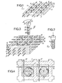
- the switch element of FIG. 1 is constituted by a square grid 1 of insulating plastic material having square openings 2 forming alignments parallel to the external sides 3 to 6 of the grid. In the alignments, the openings 2 are regularly spaced.
- Metal bands or beams, which will be designated more generally hereinafter by wires 7, pass right through the grid 1 perpendicular to the sides 3 and 5.
- Each wire 7 passes through an alignment of openings 2 parallel to the sides 4 and 6, with in each opening crossed an apparent segment 8.
- the height of each wire 7 is less than the thickness of the grid 1 with its longitudinal axis in the median plane of the grid. As also shown in the plan view of FIG.
- Fig. 1 indicates that all the threads of a grid are offset in the same direction relative to the centers of the openings they pass through.
- the ends 9 of the wires 7, which are located outside the grid, are used to connect the beams to connecting cables.
- the wires 7 are electrically conductive and made of a material whose elasticity is compatible with a reasonable contact pressure.
- Sheet 49 of FIG. 2 is a plug of a known type. It comprises a cylindrical body around which are provided circular contact rings 50 of the same height as 25 and separated from one another as 25, 26 and 27.
- the head 51 of 49 does not have a slot.
- the plug 49 is designed to be inserted manually into the stack 35 to create contacts by plugging in, which can be advantageous in rudimentary switches. In this case, to saturate a matrix, it suffices a number of plugs 49 equal to the numbers of wires on the shortest side of the matrix.
- FIG. 3 shows a stack of grids 10 to 15, all identical to grid 1.
- the layers 16, 18 and 20 of the grids 10, 12 and 14 are oriented in a direction perpendicular to the plies 17, 19 and 21 of the grids, 11, 13 and 15.
- FIG. 3 also shows a plug 22 comprising a cylindrical body 23 provided with a head 24, the assembly of 23 and 24 being made of insulating plastic.
- the body 23 carries contact strips 25, 26 and 27, all identical, made of metal or a good conductive alloy.
- the contact strips 25 to 27 are regularly spaced along the body. They do not completely surround the body 23 and have a height of the order of the thickness of a grid plus the height of a wire 7.
- Fig. 4 the cross section of the plug 22 has been shown in the plane passing through the strip 25. It appears that the diameter of the body 23 is less than a + h so that the body 23 alone can be introduced into a grid opening without simultaneously carrying on the edges of the grid and the wire segment 8.
- the section of the strip 25 is substantially in an arc of 270 °, the diameter of the circle of 25 being greater than that of 23.
- the extreme edges 28 and 29 of 25 are rolled up on themselves and are housed in longitudinal grooves 30 and 31 hollowed out in the body 23. Given the difference in diameter between 25 and 23, the strip 25 progressively moves away from the surface of 23 from from its edges 28 and 29.
- the diameter of 25 is such that the whole of the body 23 and of the strip 25 comes into contact with the sides of the square defined by the wire 16, the wire 17 and the faces of the corresponding openings. Under these conditions, the strip 25 deforms and balances each contact, allowing easier rotations.
- the height of the strip 25 is greater than the thickness of a grid, but less than twice this thickness. Therefore, the strip 25 can come into contact with both the wires 16 and 17.
- FIG. 4 shows the plug 22 in the working position, 25 being in contact with 16 and 17. It also shows a second plug 32, identical to 22, but turned a quarter of a turn, in an anticlockwise direction , so that 25 is only in contact with 17. The plug 32 is in the rest position.
- the head 24 of the plug 22 is provided with a slot 33 making it possible to turn the plug a quarter of a turn anticlockwise or in the direct direction to put it at rest or again at job. It will be noted that if the plug 22 is turned a quarter of a turn clockwise, it remains in the working position. In practice, as will be seen below in describing the control device, the plug 22 can only take two positions, without ambiguity.
- each grid includes 4x4 openings 2 allows the insertion of four plugs, such as 22, to make four separate connections.
- the stack of FIG. 3 has only been shown as an example to illustrate the basic structure of the switch according to the invention.
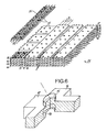
- a stack 34 formed from elongated grids, such as the grid 35 shown before it is placed on the stack.
- the grid 35 has a rectangular shape comprising four lines of openings 2, each line having 19 openings.
- the grid 35 is crossed by a sheet of four conducting wires 36, each of which passes respectively through a line of openings, parallel to the length of the grid 35.
- the respective positions of the bare segments of the wires are identical to those of the grid 1.
- the grid 35 differs from the grid 1 only in that in one direction it has a greater number of openings.
- the stack 34 is formed of hit levels 37 to 44, each level being formed by four grids 35 arranged parallel next to each other, their long sides being adjacent. In each level, the adjacent grids 35 are separated from each other by an interval t equal to the pitch of the openings in the grid 35.
- the grids of the odd levels 37, 39, 41 and 43 are oriented in the same direction while that the grids of even levels 38, 40, 42 and 44 are oriented in the perpendicular direction.
- the levels being superimposed, the openings create vertical alignments as in the stack in Fig. 2.
- a grid of the type of that of 35 consists of n lines of holes, which corresponds to a sheet of n conductive wires parallel to the pitch p. Each line can include q holes.
- Length and width are then obtained by multiplying n and q by the step p.
- a basic grid may include a sheet of 10 conductors with a pitch of 5 mm. Each conductor has a section of 1 x 0.2 mm and the grid with a thickness of 2.5 mm is overmolded on the sheet.
- the length of a grid can reach 120 steps or more. To obtain the grids, a very long strip is made overmolded on a sheet of wire, then the strip is cut to the desired length.
- Fig. 6 shows a cylindrical tenon 45 provided at a crossing point of two bars 46 and 47 of the grid 35 on one face of this grid.
- a cylindrical blind hole 48 On the other face of the grid, opposite the tenon 45, there is provided a cylindrical blind hole 48.
- the grid 35 thus comprises a certain number of torque composed of a tenon 45 and a blind hole 48, and it the same is true of the other grids of the stack 34.
- These couples are provided to ensure the correct positioning of the superimposed grids, a lug 45 of a lower grid being received in a corresponding hole of the immediately upper grid.
- the distribution of the pairs takes account of the fact that from one level to another the direction of the grids changes and that empty intervals are provided between parallel grids of a level.
- the tenons and the holes are produced during the overmolding of the wires 36 to obtain the grid.
- the battery 35 thus obtained is rigid and solid, and, moreover, practically dustproof.
- a stack 35 comprising eight levels.
- fourteen levels are required, which leads to a thickness of 10 mm.
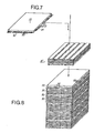
- a battery 35 which is capped with a control module 52.
- the control module supports the heads of the switching plugs which are inserted in the holes of the battery 35 when the module 52 is installed
- the module 52 includes selection bars 53 which pass right through it and the first ends of which are visible on the side 54 of the module. It also includes control bars 55 which pass right through it and whose first ends are visible on the side 56 of the module. We will see in the following how by pushing or pulling these bars 53 and 55 in an adequate way, we can turn the plugs a quarter of a turn to the right or to the left, to obtain the closing or opening of crossing in the matrix formed by the stack 35.
- the sections of the bars 55 are in the form of an inverted T, the soles of the T serving to retain the heads of the plugs.
- the module 52 is, moreover, provided on its upper face with studs, not shown, of the type 45 and has holes 48 on its lower face. Thus, by its holes 48, the module 52 fits well on the first level of 3.5.
- Fig. 8 shows that it is possible to constitute columns of stacks 35, respectively surmounted by their modules 52, stacked one on the other.
- the lugs 45 of the modules 52 allow the positioning of the stack immediately above. Obviously, such a column is only possible because the bars 53 and 55 of the control modules are accessible from the sides.
- Figs. 9a to 9b illustrate the structure of a control module 52, as well as its operation.
- a conducting wire 57 carried by a bar 58 of a grid 35
- a conducting wire 59 carried by a bar 60 of another grid 35 placed under the first and oriented perpendicularly
- a plug 61 constituted by a body 62, similar to 23, and a head 63.
- the body 62 carries a contact strip 64, similar to 25.
- the head 63 has a cylindrical bottom part 65, which rests on the edges of the soles of the work bars 55 adjacent to a T-shaped profile and a crescent-shaped upper part 66 having a cylindrical bulge at its center.
- Fig. 9a there has been shown a conducting wire 57 carried by a bar 58 of a grid 35
- a conducting wire 59 carried by a bar 60 of another grid 35 placed under the first and oriented perpendicularly
- a plug 61 constituted by a body 62, similar to
- FIG. 10 which is a plan view, schematically shows a certain number of heads 64 showing, for each one a crescent 66 comprising a cylindrical external part of the same diameter as 65, two horns 67a and 67b, as well as the bulged cylindrical part 68 of which the axis coincides with that of 65.
- Each horn 67a or 67b is connected to the cylinder 68 by a concave surface 69a and 69b.
- the ends of the horns 67a and 67b intervene directly in the state switching of the plug, while the central part 68 is only retained to make the crescent less fragile.
- a selection bar 53 and two working bars 55a and 55b have also been shown.
- the selection bar 53 is parallel to the wire 57 while the bars 55a and 55b are parallel to the wire 59. More specifically, the bar 53 is in the vertical plane of the bar, not shown, parallel to 60 on the other side of plug 61, the bar 55a is in the vertical plane of the bar 58, and the bar 55b is in the vertical plane of the bar, not shown, parallel to 58 on the other side of the plug 61.
- the selection bar 53 has the shape of a comb, the teeth 70a, 70b, 70c, etc., are flexible and are arranged in a pitch equal to the pitch of the grids.
- the back of comb 53 is located substantially above the top of the heads 64 of the plugs 61 and the teeth are long enough so that their lower parts are at the level of the horns 67a and 67b, but above the base 65.
- Each work bar 55a or 55b carries rigid teeth, such as 71 a and 71b, which are distributed along the bar according to the pitch of the grids.
- the bottom of the bar 55a or 55b is below the base 65 and the top of the teeth 71 a or 71 b is at a level higher than the bottom of the teeth 70a, 70b, ...
- the selection bar 53 is placed so that each tooth 70a, 70b, 70c, etc., is respectively opposite the axis of a plug 61.
- the working bars 55a and 55b are placed so that the teeth are respectively opposite the axes of the plugs.
- the width of a tooth 70a, 70b, etc. is such that, in the position indicated, the working bars 55a and 55b can be moved without the teeth 71a or 71b touching the teeth 70a or 70b, but pass freely between them.
- the bar 53 can be moved with its teeth passing between the teeth of the working bars.
- the plug 61 is in a position such that the horn 67a is further from the tooth 70b than the horn 67b.
- the contact strip 64 is then in contact only with the wire 57 and the current cannot pass from 57 to 59.
- FIG. 9b illustrates the operation of the switching which switches the plug 61 from the rest state to the working state.
- the bar 53 is first of all pushed in the direction of the arrow F1, by means not shown, so that the part of the tooth 70b which was in front of the horn 67a comes in front of the horn 67b.
- the other part of tooth 70b is then in front of tooth 71b of the work bar 55b.
- the bar 55b is pushed, in the direction of the arrow F2, so that the tooth 71 pushes the flexible bottom of the tooth 70b, which comes into contact with the horn 67b of the head of the plug, then pushes this horn which causes the rotation of the plug 61.
- the stroke of the working bar 55b is such that the plug 61 rotates a quarter of a turn, so that the contact strip 64 comes into contact, at the same time, with the wires 57 and 59.
- the current can go from 57 to 59.
- the bar 55b is released so that it returns to its initial position in FIG. 9a, for example under the action of a return spring not shown.
- the selection bar 53 is released and returns to its initial position, for example also under the action of a return spring.
- the plug 61 keeps the position it has reached during the switching so that the contact is maintained without external energy supply and without causing mechanical stress, as in some switches where an element remains stuck in extension.
- FIG. 9c illustrates the operation of the switching which switches the plug 61 from the working state to the resting state.
- the bar 53 is firstly pulled in the direction of the arrow F3, by means not shown, so that the part of the tooth 70b which was, at rest, in front of the horn 67b comes in front of the horn 67a.
- the other part of tooth 70b is then in front of tooth 71a of the work bar 55a.
- the bar 55a is pushed, in the direction of the arrow F2, so that the tooth 71 has pushes the flexible bottom of the tooth 70b, which comes into contact with the horn 67a of the head of the plug, then pushes this horn which causes the rotation of the plug 61.
- the stroke of the working bar 55a is such that the plug 61 turns backwards by a quarter of a turn, so that it returns to the rest position indicated in the Fig. 9a. Then, the selection bars 53 and working bars 55a are released, as described in relation to FIG. 9b.
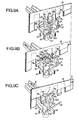
- Fig. 10 which partially shows a matrix of file heads 61 associated with a selection busbar 53.1, 53.2, 53.3, ..., and a working busbar 55.1, 55.2, 55.3, ..., makes it possible to illustrate the operation of a module 52.
- the selection bars 53.1 to 53.5 are each represented by a small horizontal rectangle, to the right of the matrix, with, in its horizontal extension, double horizontal lines symbolizing the flexible teeth 70 of the bars.
- the working bars 55.1 to 55.6 are each represented by a small vertical rectangle, under the matrix, with, in its vertical extension, a series of small vertical rectangles symbolizing the rigid teeth 71 of the bars.
- the vertical line 88 indicates the position of the ends of the selection bars and the horizontal line 89 that of the ends of the working bars at rest.
- the bar 53.2 has been pushed towards the die, in the position indicated in FIG. 9b, then the work bar 55.5 has been pushed as in FIG. 9b, so that the head of the card for the second row and the fourth column has been turned in the direction of the arrow, ie put to work.
- the bar 53.4 has, on the contrary, been pulled towards the outside of the matrix and the bar 55.2 has been pushed, as in FIG. 9c, so that the head of the card of the fourth row and of the second column is turned in the direction of the arrow, that is to say put to rest.
- each level can be manufactured in a modular fashion, the basic modular element 35 consisting of a sheet of conductors parallel to the pitch p.
- the connections of the inputs and outputs can be made respectively on the faces of the parallelepiped of FIG. 8, which correspond respectively to the sides 56 and 54 of the modules 52, the other two faces being able to be used for testing the circuitry as well as for controlling the bars 53 and 55.
- Fig. 11 1 highlights the advantages of this type of battery. If we share the stack along an axis passing through a diagonal which leaves on the same side 54 and 56, we delimit two zones 74 and 75, i.e. zone 74 devolved to the line and installation teams, and the zone 75 reserved for the operating department. In zone 74, the side 56 receives the incoming cable conductors 76 and the side 54 receives the outgoing cable conductors 77 to the central office. Certain inter-matrix connections are possible in the factory. The other two sides 72 and 73 are assigned to the command and to the tests (link interruption, realization of bypass, etc.).
- Fig. 12 there is shown a series of batteries of FIG. 8 mounted vertically between two cable trays 78 and 79 respectively for the incoming cables 76 and the outgoing cables 77.
- the stacks are oriented so that their diagonals are aligned, all leaving the installation area 74 on one side and on the other side, the operating area 75.
- a series of batteries of FIG. 8 mounted horizontally on means not shown, between two cable trays 80 and 81 similar to 78 and 79.
- the diagonal planes of the stacks are aligned to separate zones 74 and 75.
- Fig. 14 shows two distributor bays formed from stacks of FIG. 8, in which the dies are mounted on a vertical axis 82 which makes it possible to extract them from the stack by rotating them, as indicated by the arrows, to have access to the entire surface of each matrix when it is desired to establish or break a connection by acting on the plug heads.
- the cables are passed through a chute 83 and therefore undergo twists with each operation of the matrix.
- each bay comprises two stacks of dies with, at the rear, in the central part, the cable trays 84.
- the management principle remains the same, the dies being articulated on the same vertical axis 90 and being arranged symmetrically with respect to to this one.
- This arrangement of FIG. 15 should take up less space than that of FIG. 14.
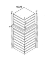
- FIG. 16 a fully automated distributor bay, the visible side of the stack overlooking the operating area.
- the matrices are fixed.
- the member 87 has the shape of a right angle whose plane is perpendicular to that of the rails 85 and 86, and is therefore parallel to those of the levels of the dies or also in the plane of the control devices 52.
- the rails 85 and 86 can carry racks on which roll gear wheels mounted at the end of the sides of the member 87, in order to be able to position the member 87 in front any one of the devices 52.
- the member 87 which contains means, such as core coils, not shown, in a number equal to that of the work and selection bars. Each nucleus hangs the bar which corresponds to it.
- a selection system selects the coils to be excited, in one direction or in the other, to push or pull the corresponding bar and thus cause the switching of a card in a matrix, as we have seen in relation to the Figs. 9b, 9c and 10.
- the high number of plugs with rotation control is compensated by the possibility of controlling them from a single side face of the stack and, even, automatically.
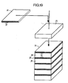
- a battery 34 has been symbolically represented, which is capped with a control module 91.
- the control module covers the heads of the switching plugs which are inserted into the holes in the battery 34 when the module 91 is installed. .
- control module 91 has the form of a cover formed by juxtaposed grooves 92 which serve as guide elements for a switching member. We will see below how by introducing a switching member in these grooves 92, it is possible to selectively rotate the heads 24 of the plugs.
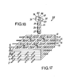
- Figs. 17 and 18 there is shown, on the one hand, the stack of grids 10 to 15 in FIG. 3 and, on the other hand, a variant 94 of the sheet 22.
- the head 93 of the plug 94 has a cylindrical base part 95 and a high part in the form of a circular sector 96 having a cylindrical bulge 97 at its center.
- the center of the cylindrical bulge 97 is surmounted by a conical pin 98.
- the body of the plug, the cylinder of 95, that of 97 and the cone 98 are of revolution about the same axis.
- the sectoral part 96 is limited by the planes 99 and 100 which make between them an angle at the center slightly less than 180 °.
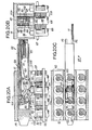
- FIG. 20a is a sectional view along the line XXA-XXA of FIG. 20b;
- Fig. 20c is a sectional view along the line XXB-XXB of FIG. 20a, the member 101 being drawn, but supposed to be transparent;
- Fig. 20b is a view in vertical section along the line XXC-XXC of FIG. 20a.
- the cylindrical parts 95 of the plugs 102 to 105 rest on the edges of the meshes of the grid 106 which supports the layer of wires 107.
- the grid 106 rests on a grid 108 which supports the layer of wires 109.
- the partitions 110 delimiting the grooves 92 of the cover 91 rest on the edges of the meshes of the grid 106 which are parallel to the wires 107.
- the width of a wall 110 is less than that of the bars of the grids, a vertical face of each partition falling practically vertically from the vertical face of the bar which is adjacent to the wire 107 and the other face of the partition falling substantially in the middle of the bar.
- the cylindrical parts 95 can rotate freely.
- the offset of each partition is explained by the fact that, in each mesh, the plug is also eccentric, as shown in FIG. 4.
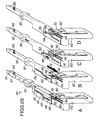
- the height of the member 101 is practically equal to the distance between the plane delimited by the top of the cones 98 and the upper bottom of each groove 92.
- the width of the member 101 is equal to the internal width of the grooves 92.
- the member 101 consists of a central beam of cross-section at 1 111 and two flat control rods 112 and 113, arranged on each side of the core of the beam at 1 111.
- the sum of the thicknesses of the rods 112, 113 and the core of 1 1 is equal to that of the soles of 1.
- the upper sole of 1 bears against the bottom of the groove 92.
- the end 114 of the part 111 which is introduced into a groove 92 is bevelled so to facilitate its introduction.
- the two sides of the lower sole 115 are cut over a certain length. Furthermore, above these cutouts, the core of 1 1 is drilled right through, and the opening or opening 116 thus obtained serves as a cam groove for two studs 117 and 118 respectively fixed in the heads 119 and 120 of the ends of the rods 112 and 113.
- the heads 119 and 120 respectively carry hooks 121 and 122 directed downwards and oriented so as to be able to exert a traction towards the entry of the groove 92.
- the heads 119 and 120 and the rod bodies are joined by parts 123 and 124 of reduced height compared to that of the rod bodies, which makes them flexible, so that the hooks 121 and 122 can be lowered on either side of the 'soul of 111, where the sole 115 is cut.
- the light 116 has a V shape, very open towards the top, with the top 125 of the V slightly extended towards the end 114 and the bottom 126 of the V towards the entrance of the groove, the bottom part 126 of the V also comprising a horizontal rectilinear stroke 127.
- Figs. 21 a to 21 c planes 99 and 100 make an angle such that the rotation of the plug is at each switching of + or -90 °.
- the distance between the rods 112 and 113 is just greater than the diameter of the cylindrical bulge 97. Since the radius of 97 is practically half that of 95, the angle of the planes 99 and 100 is very little less than 180 °.
- the conical terminations 98 limit the surface in contact with the member 101 during translations of the latter in the groove and therefore limit the parasitic torques which would tend to rotate heads of unselected plugs.
- the rods 112 and 113 are held laterally, against the web of the beam 111, by two cheeks 128 and 129.
- the sum of the thicknesses of the cheeks 128 and 129 and the width of the sole of 1 1 is equal to the width of a groove, up to the required clearance.
- FIG. 21 a shows the plug head 104 at rest, as well as the rods 112 and 113 whose hooks 121 and 122 have been shown by hatched squares.
- Fig. 21 b the rod 112 has been pulled and the hook 121 has driven the plane 100, so that the head has rotated by + 90 °.
- the width of the core of 111 is practically equal to the diameter of the central part 97 of the plug head. Therefore, when the rod 112 is pushed back to return to rest, the hook 121 can touch the lateral surface of 97, but does not cause the head to rotate.
- Fig. 21c the rod 113 has been pulled and, in a similar manner, rotates the head by -90 0 .
- the longitudinal position of the switching member in the groove must be such that the front part of the horizontal stroke 127 of 116 is slightly in front of the plane 98 while the rear part of 127 of found behind 99, or vice versa, depending on the orientation of the head. It is assumed that the member 101 is driven by a stepping motor whose pitch is equal to that of the plugs. Note that the cutouts in the soles of 115 have a length which can be less than twice the pitch of the cards and that they are practically centered on the card to be switched.
- Fig. 22 schematically shows a member 101 in front of the grooves 92 of a switching module 91.
- the arrow F2 suggests the first lateral movement to bring the member 101 in front of the selected groove and the arrow F3 suggests the longitudinal movement of the member in the groove to bring the cutouts of 115 above the head to switch.
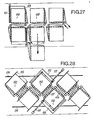
- FIG. 23 there is shown a stack 34, surmounted by a cover 91, in which the sheets are all oriented with the head up, as indicated on the left part of the drawing. The pitch of the grooves is then equal to the pitch p of the sheets in their grids.
- FIG. 24 there is shown a stack 34 ', surmounted by an upper cover 91' and resting on a lower cover 91 ", in which the plugs are alternately oriented head up and head down, as indicated on the left part of the drawing
- the pitch of the grooves of the modules 91 ′ and 91 " is then equal to twice the pitch p of the plugs, ie equal to 2 p.
- the arrangement of FIG. 24 allows the use of heads 93 ′ of larger diameter, which has the advantage of doubling the active torque when the rods 112 and 113 of the switching members are actuated.
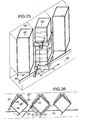
- Fig. 25 there is shown schematically in perspective a series of stacks of FIG. 9, mounted vertically.
- the batteries 130 are oriented so that their diagonals are aligned, leaving all on one side the installation area 131 and on the other side the operating area 132.
- a machine 133 which can be moved on a rail 134 parallel to the bays 130, as indicated by the arrows F4.
- the bays 130 are provided with vertical rails or racks 135 making it possible to ensure the vertical displacement of the automaton 133 which carries a switching member 101, which can be moved laterally and longitudinally. It is also assumed that the automaton 133 includes means for pulling and pushing the rods 112 and 113 of the member 101.
- the automaton 133 makes it possible to select the bay, to select the switching module 91 in the bay, the groove 92 in the module 91, to introduce the member 101 in the groove, to order the appropriate rod to make a connection or a disconnection, then to remove the member 101 from the groove. After an operation, the machine can return to the base of the bay. For all these operations, stepper motors can be provided in the PLC. It is clear that the positioning of a switching member can be fully automatic, as well as the operation of the rods 112 and 113. As a result, the switching operations inside the distributor can be fully automated, which has an important advantage. .
- Fig. 26 highlights the advantages of this type of battery.
- Two zones 131 and 132 are delimited, zone 131 being assigned to the line and installation teams and zone 132 being reserved for the operating service.
- the side 136 receives the conductors of the incoming cables 137 and the side 138 receives the conductors of outgoing cables 139 to the central office.
- Certain inter-battery connections can be made at the factory.
- the 140 side is assigned to the command and to the tests (link interruption, realization of bypass, etc.).
- Fig. 27 shows an example of a span made up of two rows of attachable bays 130. This very compact arrangement requires moving (see arrow F5) modules' stackable during connection.
- Fig. 28 shows another example of a double row bay bay 130. This staggered arrangement allows direct access to the incoming 137 and outgoing 139 cables.
- Figs. 29a to 29d schematically represent a manual intervention tool 141 which makes it possible to actuate the plug heads like a member 101.
- the tool 141 comprises a member 101 mounted, in the manner of a pistol barrel, on a stock 142.
- the external ends of the rods 112 and 113 are subjected to the action of compressed springs 143 and 144 which tend to repel them. towards the end 114.
- the stick 142 is provided with a trigger 145 which makes it possible to push a lever 150 towards the rear of the tool, as indicated by arrow F6.
- a slider 146 is mounted astride the rear part of 101.
- the slider 146 has a slot 147 open upwards in the shape of a V, with an extension horizontal at the top, like slot 116.
- the center of slot 147 is perpendicular to the median plane of rods 112 and 113.
- the ends of slot 147 are straight and parallel to the axis of 101, one 148 above 112 and the other 149 above 113.
- the lever 150 integral with the trigger 145 has its upper end which passes through the slot 147.
- the trigger 145 is pressed, the lever 150 abuts the curved part (towards 113) of the rod 112 so that the rod 112 is pulled and can actuate a plug head as described in relation to Figs. 20a to 20c.
- the end of the lever 150 is offset towards the rod 113.
- the trigger 145 is pressed, the lever 150 abuts on the curved part (towards 112) of the rod 113 so that the rod 113 is pulled and can actuate a plug head.
- FIG. 29a shows the pistol 97 in the rest state, the slide 107 being positioned correctly so that the heads 75 and 76, symbolically represented by a square 108, can be, once the member is pressed, above the head to switch.
- Fig. 29b shows the position of the slide 146 for carrying out a connection operation, the trigger 145 being able to pull the rod 112.
- Fig. 29c shows the position of the slide 146, pulled back, to prepare a disconnection operation.
- Fig. 29d shows the action of the trigger 145 on the lever 150 which drives the rod 113 for a disconnection operation.
Landscapes
- Engineering & Computer Science (AREA)
- Power Engineering (AREA)
- Computer Networks & Wireless Communication (AREA)
- Structure Of Telephone Exchanges (AREA)
- Push-Button Switches (AREA)
Description
La présente invention concerne un commutateur à matrices à plusieurs couches de points de croisement selon le préambule de le revendication 1. Ces commutateurs sont utilisables notamment dans des répartiteurs téléphoniques ou autres, ou dans des dispositifs semblables. Plus particulièrement, l'invention concerne un tel commutateur à sélection par coordonnées.The present invention relates to a matrix switch with several layers of crossing points according to the preamble of
Les commutateurs téléphoniques à barres croisées sont connus depuis fort longtemps. Récemment, on a développé des commutateurs à plusieurs couches tels que ceux qui sont décrits dans les brevets FR-A-1 584 604 et FR-A-2 106 738. Ces commutateurs se composent de plusieurs premières nappes de fils parallèles orientés dans une première direction et de plusieurs secondes nappes de fils parallèles intercalés entre les premières nappes et orientées dans une direction perpendiculaires aux premières nappes. On définit ainsi, dans une direction normale aux nappes de fils, des points de croisement multiples qui sont ouverts ou fermés par des sortes de fiches multicontacts déplacées perpendiculairement aux nappes. Dans le brevet FR-A-2 038 444, on utilise également des fiches multicontacts que l'on fait tourner pour fermer ou rompre les contacts. Ces commutateurs ont été conçus pour constituer des commutateurs à fonctionnement rapide intervenant dans l'établissement de communications entre les abonnés.Cross bar telephone switches have been known for a long time. Recently, multi-layer switches have been developed such as those described in patents FR-A-1,584,604 and FR-A-2,106,738. These switches consist of several first layers of parallel wires oriented in a first direction and several second layers of parallel threads interposed between the first layers and oriented in a direction perpendicular to the first layers. We thus define, in a direction normal to the plies of wires, multiple crossing points which are open or closed by sorts of multi-contact plugs displaced perpendicular to the plies. In patent FR-A-2 038 444, multi-contact plugs are also used which are rotated to close or break the contacts. These switches have been designed to constitute fast-functioning switches involved in establishing communications between subscribers.
Par ailleurs, dans un répartiteur général, il est nécessaire de pouvoir relier, sans blocage, un circuit d'entrée à un circuit de sortie puisque le remplissage du répartiteur dépend en premier lieu de la demande des abonnés. De façon classique, les câbles d'arrivée et de départ sont raccordés sur des têtes verticales pour les uns et des réglettes horizontales pour les autres au moment de l'installation. Puis lorsque l'on veut établir une liaison, on relie le circuit d'arrivée au circuit de départ sélecté au moyen de jarretières. Ces jarretières ont deux fils dans le cas d'un abonné et jusqu'à sept fils dans le cas de circuits basse fréquence en transmissions.Furthermore, in a general distributor, it is necessary to be able to connect, without blocking, an input circuit to an output circuit since the filling of the distributor depends first of all on the demand of the subscribers. Conventionally, the incoming and outgoing cables are connected to vertical heads for some and horizontal strips for others at the time of installation. Then when one wants to establish a connection, one connects the circuit of arrival to the circuit of departure selected by means of garters. These jumpers have two wires in the case of a subscriber and up to seven wires in the case of low frequency circuits in transmissions.
En exploitation normale, il est souvent nécessaire de modifier le câblage du répartiteur et on peut estimer que les jarretières sont en moyenne changées de place une fois par an. Lorsque les jarretières sont très nombreuses, leur poids et les enchevêtrements qu'elles provoquent font qu'il devient impossible de les retirer du répartiteur, si bien qu'on en ajoute sans cesse ce qui engorge encore un peu plus les passages. L'accessibilité aux différents endroits du répartiteur oblige à espacer les éléments, donc à augmenter les dimensions de celui-ci, nécessite la présence de plusieurs agents et rend difficilement mécanisable le travail de gestion et d'exploitation de ces répartiteurs.In normal operation, it is often necessary to modify the wiring of the distributor and it can be estimated that the jumpers are changed on average once a year. When the garters are very numerous, their weight and the tangles which they cause make that it becomes impossible to remove them from the distributor, so that one ceaselessly adds them which clogs up the passages a little more. Accessibility to the different locations of the distributor requires spacing the elements, therefore increasing the dimensions thereof, requires the presence of several agents and makes it difficult to mechanize the work of management and operation of these distributors.
Dans le brevet FR-A-2 284 240, il est décrit un système répartiteur automatique à commutateur à matrices qui sont constituées par des cartes de circuits imprimés équipés de broches associées aux conducteurs. Les cartes sont amovibles dans des alvéoles de bâtis où elles sont reliées par des câbles plats souples. A chaque opération, il faut sortir une carte, positionner un connecteur, en forme de strap, sur les broches du point de croisement choisi, puis remettre la carte en place. Cette manoeuvre est à recommencer autant de fois qu'il y a de contacts par circuit, ce qui est malcommode et constitue une source d'erreurs. De plus, l'apparente simplicité du système est compensée par la complexité concomitante de l'automate du système.In patent FR-A-2 284 240, there is described an automatic distributor system with matrix switch which are constituted by printed circuit boards equipped with pins associated with the conductors. The cards are removable in rack cells where they are connected by flexible flat cables. At each operation, you must remove a card, position a connector, in the form of a strap, on the pins of the selected crossing point, then replace the card. This maneuver is to be repeated as many times as there are contacts per circuit, which is awkward and constitutes a source of errors. In addition, the apparent simplicity of the system is offset by the concomitant complexity of the system controller.
Par ailleurs, dans le brevet US-A-3 312 792, il est décrit une matrice de commutation à une couche de points de croisement comportant une première nappe de paires de fils parallèles, orientés dans une première direction, et une seconde nappe de paires de fils parallèles, orientés dans une direction perpendiculaire à la première. La première et la seconde nappe sont superposées. Aux points de croisement des nappes, sont prévues des fiches pouvant tourner d'un quart de tour, dans un sens ou dans l'autre, pour établir ou rompre le trajet électrique entre une paire de fils de la première nappe et une paire de fils de la seconde nappe. Dans le brevet US-A-3 312 792, les moyens utilisés pour faire tourner les fiches comprennent un pignon enfilé sur l'axe de chacune des fiches et des crémaillères. Les pignons et les crémaillères peuvent être engrenés sélectivement par des moyens d'embrayage individuels.Furthermore, in US-A-3,312,792, there is described a switching matrix with a layer of crossing points comprising a first layer of pairs of parallel wires, oriented in a first direction, and a second layer of pairs of parallel threads, oriented in a direction perpendicular to the first. The first and second layers are superimposed. At the crossover points of the plies, there are provided plugs which can turn a quarter of a turn, in one direction or the other, to establish or break the electrical path between a pair of wires of the first ply and a pair of wires of the second tablecloth. In US-A-3,312,792, the means used to rotate the plugs include a pinion threaded on the axis of each of the plugs and racks. The pinions and racks can be selectively meshed by individual clutch means.
Un objet de l'invention consiste à prévoir un commutateur permettant de réaliser des répartiteurs à matrices à plusieurs couches de points de croisement comportant des moyens capables de faire tourner sélectivement les fiches de commutation, qui évitent les inconvénients mentionnés ci-dessus et qui soient plus simples et moins onéreux qui ceux prévus dans le brevet US-A-3 312 792.An object of the invention is to provide a switch making it possible to produce matrix distributors with several layers of crossing points comprising means capable of selectively rotating the switching plugs, which avoid the drawbacks mentioned above and which are more simple and less expensive than those provided in patent US-A-3,312,792.
Un autre objet de la présente invention consiste à prévoir un organe de commande des têtes de fiches rotatives qui ne nécessite un accès que sur une face du commutateur, tout en conservant les avantages des commutateurs ci-dessus.Another object of the present invention is to provide a control member for the rotary plug heads which requires access only on one face of the switch, while retaining the advantages of the above switches.
Conformément à l'invention, les objets mentionnés ci-dessus sont atteints par la mise en oeuvre des combinaisons de moyens définies dans la partie caractérisante de la revendication principales complétée par les revendications dépendantes.In accordance with the invention, the objects mentioned above are achieved by the use of the combinations of means defined in the characterizing part of the main claim supplemented by the dependent claims.
Les caractéristiques de l'invention apparaîtront clairement à la lecture de la description suivante d'exemples de réalisation, ladite description étant faite en relation avec les dessins joints,-parmi lesquels:
- la Fig. -1 est une vue en perspective d'un exemple de réalisation d'un élément de commutateur,
- la Fig. 2 est une vue en perspective d'un fiche connue,
- la Fig. 3 est une vue éclatée d'un empilage, suivant l'invention, d'éléments selon la Fig. 1, ainsi que d'une fiche de commutateur par rotation,
- la Fig. 4 est une vue schématique en plan illustrant le fonctionnement de l'empilage de la Fig. 2,
- la Fig. 5 est une vue en perspective éclatée d'un empilage obtenu avec des éléments plus longs dérivés de celui de la Fig. 2,
- la Fig. 6 est une vue en perspective, avec coupes partielles, d'un détail d'un élément de l'empilage de la Fig. 5,
- la Fig. 7 est une vue éclatée schématique en perspective illustrant la construction de l'empilage de la Fig. 5,
- la Fig. 8 est une vue schématique en perspective d'une colonne formée par la superposition d'empilage de la Fig. 7,
- les Figs. 9a à 9c sont des vues en perspective d'un point de croisement de commande d'un exemple de réalisation d'un module de commande utilisable avec les empilages des
- Figs. 7 et 8, dans trois états différents de fonctionnement,
- la Fig. 10 est une vue schématique en plan illustrant le fonctionment des points de croisement, selon les Figs. 9a à 9c, dans un module de commande,
- la Fig. 11 est une vue schématique en plan des deux colonnes adjacentes, suivant la Fig. 8, avec ses câbles de raccordement,
- la Fig. 12 est une vue schématique en perspective d'un premier exemple de réalisation d'un ensemble de colonnes de commutation de la Fig. 8,
- la Fig. 13 est une vue schématique en perspective d'un second exemple de réalisation d'un ensemble de colonne de commutation de la Fig. 8,
- la Fig. 14 est une vue schématique en plan d'un montage de colonnes de la Fig. 8,
- la Fig. 15 est une vue schématique en plan d'une variante du montage de la Fig. 14,
- la Fig. 16 est une vue schématique d'un dispositif de commande de sélection utilisable avec une colonne de la Fig. 8,
- les Figs. 17 et 18 montrent respectivement, d'une part, la pile de la Fig. 2 et, d'autre part, une variante de la fiche de la Fig. 2,
- la Fig. 19 est une vue d'une pile formée d'empilages adaptés aux fiches de la Fig. 17,
- les Figs. 20a à 20c sont respectivement des vues en élévation, de bout et en plan de la partie active d'un organe de commande de commutation adaptés aux fiches de la Fig. 17,
- les Figs. 21 a à 21 sont des vues schématiques montrant les changements d'états d'une fiche de commutation, suivant la Fig. 17,
- la Fig. 22 est une vue schématique illustrant le positionnement de l'organe de commande des Figs. 20a à 20c,
- la Fig. 23 est une vue schématique montrant un premier exemple d'orientation des fiches,
- la Fig. 24 est une vue montrant une second exemple d'orientation des fiches,
- la Fig. 25 est une vue illustrant la disposition de piles, suivant la Fig. 19, associées à un système de positionnement d'organes de commande,
- la Fig. 26 est une vue en plan de l'ensemble des piles de la Fig. 25,
- la Fig. 27 montre une variante de la disposition de la Fig. 26,
- la Fig. 28 est une vue d'une autre variante de disposition, et
- les Figs. 29a à 29d sont des vues schématiques en perpective d'un outil manuel de commande de commutation des fiches, dont l'objet est le même que celui de l'organe des Figs. 20a à 20c.
- Fig. -1 is a perspective view of an exemplary embodiment of a switch element,
- Fig. 2 is a perspective view of a known plug,
- Fig. 3 is an exploded view of a stack, according to the invention, of elements according to FIG. 1, as well as a switch plug by rotation,
- Fig. 4 is a schematic plan view illustrating the operation of the stack of FIG. 2,
- Fig. 5 is an exploded perspective view of a stack obtained with longer elements derived from that of FIG. 2,
- Fig. 6 is a perspective view, with partial sections, of a detail of an element of the stack of FIG. 5,
- Fig. 7 is a schematic exploded perspective view illustrating the construction of the stack of FIG. 5,
- Fig. 8 is a schematic perspective view of a column formed by the stacking superposition of FIG. 7,
- Figs. 9a to 9c are perspective views of a control crossing point of an exemplary embodiment of a control module usable with the stacks of
- Figs. 7 and 8, in three different operating states,
- Fig. 10 is a schematic plan view illustrating the operation of the crossing points, according to FIGS. 9a to 9c, in a control module,
- Fig. 11 is a schematic plan view of the two adjacent columns, according to FIG. 8, with its connection cables,
- Fig. 12 is a schematic perspective view of a first embodiment of a set of switching columns of FIG. 8,
- Fig. 13 is a schematic perspective view of a second embodiment of a switch column assembly of FIG. 8,
- Fig. 14 is a schematic plan view of an assembly of columns of FIG. 8,
- Fig. 15 is a schematic plan view of a variant of the assembly of FIG. 14,
- Fig. 16 is a schematic view of a selection control device usable with a column of FIG. 8,
- Figs. 17 and 18 show, on the one hand, the stack of FIG. 2 and, on the other hand, a variant of the plug of FIG. 2,
- Fig. 19 is a view of a stack formed of stacks adapted to the sheets of FIG. 17,
- Figs. 20a to 20c are respectively elevation, end and plan views of the active part of a switching control member adapted to the plugs of FIG. 17,
- Figs. 21 a to 21 are schematic views showing the changes of states of a switching plug, according to FIG. 17,
- Fig. 22 is a schematic view illustrating the positioning of the control member of FIGS. 20a to 20c,
- Fig. 23 is a schematic view showing a first example of orientation of the sheets,
- Fig. 24 is a view showing a second example of orientation of the sheets,
- Fig. 25 is a view illustrating the arrangement of batteries, according to FIG. 19, associated with a positioning system for control members,
- Fig. 26 is a plan view of all the batteries in FIG. 25,
- Fig. 27 shows a variant of the arrangement of FIG. 26,
- Fig. 28 is a view of another alternative arrangement, and
- Figs. 29a to 29d are schematic perspective views of a manual plug switching control tool, the object of which is the same as that of the member of FIGS. 20a to 20c.
L'élément de commutateur de la Fig. 1 est constituée par une grille carrée 1 en matière plastique isolante présentant des ouvertures carrées 2 formant des alignements parallèles aux côtés externes 3 à 6 de la grille. Dans les alignements, les ouvertures 2 sont régulièrement espacées. Des bandes ou poutres métalliques, que l'on désignera plus généralement dans la suite par des fils 7, traversent de part en part la grille 1 perpendiculairement aux côtés 3 et 5. Chaque fil 7 traverse un alignement d'ouvertures 2 parallèle aux côtés 4 et 6, avec dans chaque ouverture traversée un segment apparent 8. La hauteur de chaque fil 7 est inférieur à l'épaisseur de la grille 1 avec son axe longitudinal dans le plan médian de la grille. Comme l'indique également la vue en plan de la Fig. 3, dans chaque ouverture 2, le segment associé 8 ne passe pas par le centre de l'ouverture 2, mais est déporté d'une distance r inférieure au côté de l'ouverture. La Fig. 1 indique que tous les filss d'une grille sont déportés dans le même sens par rapport aux centres des ouvertures qu'ils traversent. Les bouts 9 des fils 7, qui se trouvent à l'extérieur de la grille, servent au raccordement des poutres à des câbles de liaison. Les fils 7 sont conducteurs de l'électricité et fabriquées en un matériau dont l'élasticité est compatible avec une pression de contact raisonnable.The switch element of FIG. 1 is constituted by a
La fiche 49 de la Fig. 2 est une fiche d'un type connu. Elle comprend un corps cylindrique autour duquel sont prévus des anneaux circulaires de contact 50 de même hauteur que 25 et séparés les uns des autres comme 25, 26 et 27. La tête 51 de 49 ne comporte pas de fente. En pratique, la fiche 49 est prévue pour être enfichée manuellement dans la pile 35 pour y créer des contacts par enfichage, ce qui peut être intéressant dans des commutateurs rudimentaires. Dans ce cas, pour saturer une matrice, ill suffit d'un nombre de fiches 49 égal aux nombres de fils sur le côté le plus court de la matrice.
La Fig. 3 montre une pile de grilles 10 à 15, toutes identiques à la grille 1. Les nappes 16, 18 et 20 des grilles 10, 12 et 14 sont orientées dans une direction perpendiculaire aux nappes 17, 19 et 21 des grilles, 11, 13 et 15. La Fig. 3 montre également une fiche 22 comportant un corps cylindrique 23 pourvu d'une tête 24, l'ensemble de 23 et 24 étant en matière plastique isolante. Le corps 23 porte des lamelles de contact 25, 26 et 27, toutes identiques, en métal ou alliage bon conducteur. Les lamelles de contact 25 à 27 sont régulièrement espacées le long du corps. Elles n'entourent pas complètement le corps 23 et ont une hauteur de l'ordre de l'épaisseur d'une grille plus la hauteur d'un fil 7.Fig. 3 shows a stack of
A la Fig. 4, on a montré la section transversale de la fiche 22 dans le plan passant par la lamelle 25. Il apparaît que le diamètre du corps 23 est inférieur à a+h de manière que le corps 23 seul puisse être introduit dans une ouverture de grille sans porter simultanément sur les bords de la grille et le segment de fil 8. La section de la lamelle 25 est sensiblement en arc de cercle de 270°, le diamètre du cercle de 25 étant supérieur à celui de 23. Les bords extrêmes 28 et 29 de 25 sont enroulés sur eux- mêmes et se logent dans des rainures longitudinales 30 et 31 creusées dans le corps 23. Etant donné la différence de diamètre entre 25 et 23, la lamelle 25 s'écarte progressivement de la surface de 23 à partir de ses bords 28 et 29. Le diamètre de 25 est tel que l'ensemble du corps 23 et de la lamelle 25 entre en contact avec les côtés du carré défini par le fil 16, le fil 17 et les faces des ouvertures correspondantes. Dans ces conditions, la lamelle 25 se déforme et équilibre chaque contact, en permettant des rotations plus faciles.In Fig. 4, the cross section of the
Comme on l'a mentionné ci-dessus, la hauteur de la lamelle 25 est supérieure à l'épaisseur d'une grille, mais inférieure au double de cette épaisseur. Donc, la lamelle 25 peut entrer en contact, à la fois, avec les fils 16 et 17.As mentioned above, the height of the
En fait, la Fig. 4 montre la fiche 22 en position de travail, 25 étant en contact avec 16 et 17. Elle montre également une seconde fiche 32, identique à 22, mais tournée d'un quart de tour, dans le sens inverse des aiguilles d'une montre, si bien que 25 n'est plus en contact qu'avec 17. La fiche 32 est en position de repos.In fact, FIG. 4 shows the
La tête 24 de la fiche 22 est pourvue d'une fente 33 permettant de faire tourner la fiche d'un quart de tour dans le sens inverse des aiguilles d'une montre ou dans le sens direct pour la mettre au repos ou à nouveau au travail. On notera que, si on tourne la fiche 22 d'un quart de tour dans le sens des aiguilles d'une montre, elle reste en position de travail. En pratique, comme on le verra dans la suite en décrivant le dispositif de commande, la fiche 22 ne peut prendre que deux positions, sans ambiguïté.The
En se référant à nouveau à la Fig. 3, il apparaît qu'en enfonçant la fiche 22 dans une ouverture de la pile, on ferme trois points de croisement superposés et indépendants, l'un entre un fil de la nappe 16 et un fil de la nappe 17, l'autre entre un fil de la nappe 18 et un fil de la nappe 19, et le troisième entre un fil de la nappe 20 et un fil de la nappe 21.Referring again to FIG. 3, it appears that by inserting the
La pile de la Fig. 3 dans laquelle chaque grille comprend 4x4 ouvertures 2 permet l'insertion de quatre fiches, telles que 22, pour réaliser quatre connexions distinctes. Dans la pratique, il est nécessaire de prévoir des matrices de plus grandes dimensions et des piles comportant plus de six grilles, la pile de la Fig. 3 n'ayant été montrée qu'à titre d'exemple pour illustrer la structure de base du commutateur suivant l'invention.The battery in Fig. 3 in which each grid includes
A la Fig. 5, on a représenté une pile 34 constituée à partir de grilles allongées, telles que la grille 35 représentée avant sa mise en place sur la pile. La grille 35 a une forme rectangulaire comportant quatre lignes d'ouvertures 2, chaque ligne comptant 19 ouvertures. La grille 35 est traversée par une nappe de quatre fils conducteurs 36 dont chacune passe respectivement dans une ligne d'ouvertures, parallèlement à la longueur de la grille 35. Les positions respectives des segments nus des fils sont identiques à celles de la grille 1. En fait, la grille 35 ne se distingue de la grille 1 que par le fait que dans une direction elle comporte un plus grand nombre d'ouvertures.In Fig. 5, there is shown a
La pile 34 est formé de hit niveaux 37 à 44, chaque niveau étant formé par quatre grilles 35 disposées parallèlement les unes à côté des autres, leurs grands côtés étant adjacents. Dans chaque niveau, les grilles adjacentes 35 sont séparées l'une de l'autre par un intervalle t égal au pas des ouvertures dans la grille 35. Les grilles des niveaux impaires 37, 39, 41 et 43 sont orientées dans le même sens tandis que les grilles des niveaux pairs 38, 40, 42 et 44 sont orientées dans le sens perpendiculaire. Les niveaux étant superposés, les ouvertures créent des alignements verticaux comme dans la pile de la Fig. 2. Avec quatre lignes de trous par grille, plus trois invervalles de la largeur d'une ligne de trous entre les grilles, on a donc 4x4+3x1=19 lignes de trous par niveaux ce qui correspond aux 19 trous par ligne pour constituer une pile à section carrée. Toutefois, il faut noter que les lignes des intervalles ne sont pas utilisables. Donc dans chaque niveaux, il y a une matrice de 16x 16 trous utilisables. Une telle pile permet donc de réaliser 16 connexions à quatre contacts chacune.The
D'une manière plus générale, une grille du type de celle de 35 se compose de n lignes de trous, ce qui correspond à une nappe de n fils conducteurs parallèles au pas p. Chaque ligne peut comprendre q trous. Dans le cas d'une matrice carrée, si on dispose parallèlement k grilles par niveaux, avec un intervalle de t lignes entre grilles adjacentes, on a la relation:![]()
![]()
A titre d'exemple, une grille de base peut comprendre une nappe de 10 conducteurs au pas de 5 mm. Chaque conducteur a une section de 1 x0,2 mm et la grille d'une épaisseur de 2,5 mm est surmoulé sur la nappe. La longueur d'une grille peut atteindre 120 pas ou plus. Pour obtenir les grilles, on fabrique une bande de grande longueur surmoulée sur une nappe de fils, puis on découpe la bande à la longueur voulue.For example, a basic grid may include a sheet of 10 conductors with a pitch of 5 mm. Each conductor has a section of 1 x 0.2 mm and the grid with a thickness of 2.5 mm is overmolded on the sheet. The length of a grid can reach 120 steps or more. To obtain the grids, a very long strip is made overmolded on a sheet of wire, then the strip is cut to the desired length.
La Fig. 6 montre un tenon cylindrique 45 prévu en un point de croisement de deux barreaux 46 et 47 de la grille 35 sur une face de cette grille. Sur l'autre face de la grille, en face du tenon 45, ets prévu un trou borgne cylindrique 48. La grille 35 comporte ainsi un certain nombre de couple composé d'un tenon 45 et d'un trou borgne 48, et il en est de même des autres grilles de la pile 34. Ces couples sont prévus pour assurer la bonne mise en place des grilles superposées, un tenon 45 d'une grille inférieure venant se loger dans un trou correspondant de la grille immédiatement supérieure. Evidemment la répartition des couples tient compte du fait que d'un niveau à un autre la direction des grilles change et que des intervalles vides sont prévus entre des grilles parallèles d'un niveau. Les tenons et les trous sont fabriqués au cours du surmoulage des fils 36 pour obtenir la grille. La pile 35 ainsi obtenue est rigide et solide, et, de plus, pratiquement étanche aux poussières.Fig. 6 shows a
A la Fig. 5, on a représenté une pile 35 comportant huit niveaux. En pratique, dans une application à un répartiteur de circuits de transmission, il est nécessaire d'empiler quatorze niveaux, ce qui, avec les données numériques mentionnées ci-dessus, correspond à une épaisseur de matrice de 35 mm. Dans une application à un répartiteur de lignes d'abonnés, on n'a besoin que de quatre niveaux, ce qui conduit à une épaisseur de 10 mm.In Fig. 5, there is shown a
A la Fig. 7, on a représenté symboliquement une pile 35 que l'on coiffe avec un module de commande 52. Le module de commande supporte les têtes des fiches de commutation qui sont enfichées dans les trous de la pile 35 au moment de la pose du module 52. Le module 52 comporte des barres de sélection 53 qui le traversent de part en part et dont les premières extrémités sont visibles sur le côté 54 du module. Il comporte également des barres de commande 55 qui le traversent de part en part et dont les premières extrémités sont visibles sur le côté 56 du module. On verra dans la suite comment en poussant ou tirant d'une manière adéquate ces barres 53 et 55, on peut faire tourner les fiches d'un quart de tour à droite ou à gauche, pour obtenir la fermeture ou l'ouverture de points de croisement dans la matrice constituée par la pile 35. Les sections des barres 55 sont en forme de T renversé, les semelles des T servant à retenir les têtes de fiches.In Fig. 7, there is symbolically shown a
Le module 52 est, de plus, muni sur sa face supérieure de tenons, non montrés, du type de 45 et présente sur sa face inférieure des trous 48. Ainsi, par ses trous 48, le module 52 s'emboîte bien sur le premier niveau de 3.5.The
La Fig. 8 montre que l'on peut constituer des colonnes de piles 35, respectivement surmontées de leurs modules 52, empilées les unes sur les autres. Les tenons 45 des modules 52 permettent le positionnement de la pile immédiatement supérieure. Evidemment, une telle colonne n'est réalisable que parce que les barres 53 et 55 des modules de commande sont accessibles par les côtés.Fig. 8 shows that it is possible to constitute columns of
Les Figs. 9a à 9b illustrent la structure d'un module de commande 52, ainsi que son fonctionnement. A la Fig. 9a, on a montré un fil conducteur 57 porté par un barreau 58 d'une grille 35, un fil conducteur 59 porté par un barreau 60 d'une autre grille 35 placée sous la première et orientée perpendiculairement, et une fiche 61 constituée par un corps 62, semblable à 23, et une tête 63. Le corps 62 porte une lamelle de contact 64, semblable à 25. La tête 63 comporte une partie basse cylindrique 65, qui repose sur les bords des semelles des barres de travail 55 adjacentes à un profil en T et une partie haute 66 en forme de croissant présentant un renflement cylindrique en son centre. La Fig. 10, qui est une vue en plan, montre schématiquement un certain nombre de têtes 64 faisant apparaître, pour chacune un croissant 66 comportant une partie externe cylindrique de même diamètre que 65, deux cornes 67a et 67b, ainsi que la partie renflée cylindrique 68 dont l'axe est confondu avec celui de 65. Chaque corne 67a ou 67b est raccordée au cylindre 68 par une surface concave 69a et 69b. Comme on le verra dans la suite, les bouts des cornes 67a et 67b interviennent directement dans la commutation d'état de la fiche, tandis que la partie centrale 68 n'est conservée que pour rendre le croissant moins fragile.Figs. 9a to 9b illustrate the structure of a
A la Fig. 9a, on a également montré une barre de sélection 53 et deux barres de travail 55a et 55b. La barre de sélection 53 est parallèle au fil 57 tandis que les barres 55a et 55b sont parallèles au fil 59. Plus précisément, la barre 53 se trouve dans le plan vertical du barreau, non montré, parallèle à 60 de l'autre côté de la fiche 61, la barre 55a se trouve dans le plan vertical du barreau 58, et la barre 55b se trouve dans le plan vertical du barreau, non montré, parallèle à 58 de l'autre côté de la fiche 61.In Fig. 9a, a
La barre de sélection 53 a la forme d'un peigne dont les dents 70a, 70b, 70c, etc., sont souples et sont disposées suivant un pas égal au pas des grilles. Le dos du peigne 53 est situé sensiblement au-dessus du haut des têtes 64 des fiches 61 et les dents sont assez longues pour que leurs parties inférieures soient au niveau des cornes 67a et 67b, mais au-dessus de la base 65. Chaque barre de travail 55a ou 55b porte des dents rigides, telles que 71 a et 71b, qui sont réparties le long de la barre suivant le pas des grilles. Le bas de la barre 55a ou 55b est au-dessous de la base 65 et le haut des dents 71 a ou 71 b est à un niveau supérieur au bas des dents 70a, 70b, ...The
En position de repos, comme le montre la Fig. 9a, la barre de sélection 53 est placée de manière que chaque dent 70a, 70b, 70c, etc., se trouve respectivement en face de l'axe d'une fiche 61. Les barres de travail 55a et 55b sont placées de manière que les dents se trouvent respectivement en face des axes des fiches. La largeur d'une dent 70a, 70b, etc., est telle que, dans la position indiquée, les barres de travail 55a et 55b peuvent être déplacées sans que les dents 71 a ou 71 b ne touchent les dents 70a ou 70b, mais passent librement entre elles. Réciproquement, dans la position indiquée, la barre 53 peut être déplacée avec ses dents passant entre les dents des barres de travail.In the rest position, as shown in Fig. 9a, the
Par ailleurs, en position de repos, la fiche 61 est dans une position telle que la corne 67a est plus éloignée de la dent 70b que la corne 67b. La lamelle de contact 64 n'est alors en contact qu'avec le fil 57 et le courant ne peut passer de 57 à 59.Furthermore, in the rest position, the
La vue de la Fig. 9b illustre le fonctionnement de la commutation qui fait passer la fiche 61 de l'état de repos à l'état de travail. La barre 53 est tout d'abord poussée dans le sens de la flèche F1, par des moyens non montrés, de manière à ce que la partie de la dent 70b qui était en face de la corne 67a vienne en face de la corne 67b. L'autre partie de la dent 70b se trouve alors devant la dent 71 b de la barre de travail 55b. Ensuite, la barre 55b est poussée, dans le sens de la flèche F2, si bien que la dent 71 pousse le bas flexible de la dent 70b, laquelle vient en contact avec la corne 67b de la tête de la fiche, puis pousse cette corne ce qui provoque la rotation de la fiche 61. La course de la barre de travail 55b est telle que la fiche 61 tourne d'un quart de tour, si bien que la lamelle de contact 64 vient en contact, à la fois, avec les fils 57 et 59. Le courant peut passer de 57 à 59. Ensuite, la barre 55b est relâchée si bien qu'elle reprend sa position initiale de la Fig. 9a, par exemple sous l'action d'un ressort de rappel non montré. De même, la barre de sélection 53 est relâchée et reprend sa position initiale, par exemple également sous l'action d'un ressort de rappel. La fiche 61 garde la position qu'elle a atteinte au cours de la commutation si bien que le contact se maintient sans apport extérieur d'énergie et sans entraîner de contrainte mécanique, comme dans certains commutateurs où un élément reste coincé en extension.The view of FIG. 9b illustrates the operation of the switching which switches the
La vue de la Fig. 9c illustre le fonctionnement de la commutation qui fait passer la fiche 61 de l'état de travail à l'état de repos. La barre 53 est tout d'abord tirée dans le sens de la flèche F3, par des moyens non montrés, de manière que la partie de la dent 70b qui était, au repos, en face de la corne 67b vienne en face de la corne 67a. L'autre partie de la dent 70b se trouve alors devant la dent 71 a de la barre de travail 55a. Ensuite, la barre 55a est poussée, dans le sens de la flèche F2, si bien que la dent 71 a pousse le bas flexible de la dent 70b, laquelle vient en contact avec la corne 67a de la tête de la fiche, puis pousse cette corne ce qui provoque la rotation de la fiche 61. La course de la barre de travail 55a est telle que la fiche 61 tourne à l'envers d'un quart de tour, si bien qu'elle reprend la position de repos indiquée à la Fig. 9a. Ensuite, les barres de sélection 53 et de travail 55a sont relâchées, comme décrit en relation avec la Fig. 9b.The view of FIG. 9c illustrates the operation of the switching which switches the
La Fig. 10, qui montre partiellement une matrice de têtes de fiches 61 associée à un jeu de barres de sélection 53.1, 53.2, 53.3, ..., et un jeu de barres de travail 55.1, 55.2, 55.3, ..., permet d'illustrer le fonctionnement d'un module 52. Les barres de sélection 53.1 à 53.5 sont représentées chacune par un petit rectangle horizontal, à droite de la matrice, avec, dans son prolongement horizontal, des doubles traits horizontaux symbolisant les dents flexibles 70 des barres. Les barres de travail 55.1 à 55.6 sont représentées chacune par un petit rectangle vertical, sous la matrice, avec, dans son prolongement vertical, une suite de petits rectangles verticaux symbolisant les dents rigides 71 des barres. La ligne verticale 88 indique la position des extrémités des barres de sélection et la ligne horizontale 89 celle des extrémités des barres de travail au repos. La barre 53.2 a été poussée vers la matrice, dans la position indiquée à la Fig. 9b, puis la barre de travail 55.5 a été poussée comme à la Fig. 9b, si bien que la tête de la fiche de la deuxième ligne et de la quatrième colonne a été tournée dans le sens de la flèche, c'est à dire mise au travail. La barre 53.4 a, au contraire, été tirée vers l'extérieur de la matrice et la barre 55.2 a été poussée, comme à la Fig. 9c, si bien que la tête de la fiche de la quatrième ligne et de la deuxième colonne est tournée dans le sens de la flèche, c'est à dire mise au repos.Fig. 10, which partially shows a matrix of file heads 61 associated with a selection busbar 53.1, 53.2, 53.3, ..., and a working busbar 55.1, 55.2, 55.3, ..., makes it possible to illustrate the operation of a
Il apparaît que le nombre des barres de sélection est égal au nombre des lignes de la matrice, comme le nombre des dents d'une barre de travail, et que le nombre de barres de travail est égal au nombre des colonnes de la matrice, plus un, comme le nombre des dents d'une barre de sélection. Cela explique qu'à la Fig. 7, pour le module 52, on fait apparaître des séries de quatre barres 53 sur le côté 56 et des séries de cinq barres 55 sur le côté 56.It appears that the number of selection bars is equal to the number of rows in the matrix, like the number of teeth in a working bar, and that the number of working bars is equal to the number of columns in the matrix, plus one, like the number of teeth on a selection bar. This explains why in FIG. 7, for
Il apparaît que les piles de contacts qui ont été décrites en relation avec les Figs. 5 et 8 permettent de concevoir des niveaux de surface quelconque et d'avoir un nombre de contacts quelconque par point de croisement en empilant le nombre nécessaire de niveaux. On peut ainsi construire des matrices à une paire de contacts par point de croisement pour une utilisation dans les répartiteurs d'abonnés, ou à trois paires de contacts, plus un, par point de croisement pour une utilisation dans des répartiteurs de circuits. Par ailleurs, comme le montre la Fig. 5, chaque niveau peut être fabriqué d'une façon modulaire, l'élément modulaire de base 35 se composant d'une nappe de conducteurs parallèles au pas p. Les raccordements des entrées et des sorties peuvent se faire respectivement sur les faces du parallèlépipède de la Fig. 8, qui correspondent respectivement aux côtés 56 et 54 des modules 52, les deux autres faces pouvant servir aux tests de la circuiterie ainsi qu'à la commande des barres 53 et 55.It appears that the contact batteries which have been described in relation to FIGS. 5 and 8 make it possible to design any surface level and to have any number of contacts per crossover point in a stack ant the necessary number of levels. It is thus possible to construct matrices with a pair of contacts per crossover point for use in subscriber splitters, or with three pairs of contacts, plus one, per crossover point for use in circuit distributors. Furthermore, as shown in FIG. 5, each level can be manufactured in a modular fashion, the basic
La Fig. 11 1 met en évidence les avantages de ce type de pile. Si on partage la pile selon un axe passant par une diagonale qui laisse du même côté 54 et 56, on délimite deux zones 74 et 75, c'est à dire la zone 74 dévolue aux équipes de ligne et d'installation, et la zone 75 réservée au service d'exploitation. Dans la zone 74, le côté 56 reçoit les conducteurs de câbles d'arrivée 76 et le côté 54 reçoit les conducteurs de câbles de départ 77 vers le central. Certaines liaisons inter-matrices sont réalisables en usine. Les deux autres côtés 72 et 73 sont affectés à la commande et aux tests (interruption de liaison, réalisation de dérivation, etc.).Fig. 11 1 highlights the advantages of this type of battery. If we share the stack along an axis passing through a diagonal which leaves on the
A la Fig. 12, on a montré une série de piles de la Fig. 8 montées verticalement entre deux chemins de câbles 78 et 79 respectivement pour les câbles d'arrivée 76 et les câbles départ 77. Les piles sont orientées de manière que leurs diagonales soient alignées en laissant toutes d'un côté la zone d'installatation 74 et de l'autre côté la zone d'exploitation 75.In Fig. 12, there is shown a series of batteries of FIG. 8 mounted vertically between two
A la Fig. 13, on a montré une série de piles de la Fig. 8 montées horizontalement sur des moyens non montrés, entre deux chemins de câbles 80 et 81 analogues à 78 et 79. Les plans diagonaux des piles sont alignés pour'séparer les zones 74 et 75.In Fig. 13, a series of batteries of FIG. 8 mounted horizontally on means not shown, between two
En pratique, en fonction du niveau d'automatisme désiré, on peut prévoir plusieurs variantes pour l'exploitation. La Fig. 14 montre deux baies de répartiteur formées de piles de la Fig. 8, dans lesquelles des matrices sont montées sur un axe vertical 82 qui permet de les extraire de la pile en les faisant tourner, comme indiqué par les flèches, pour avoir accès à la totalité de la surface de chaque matrice lorsqu'on désire établir ou rompre une connexion en agissant sur les têtes de fiches. Les câbles sont passés dans une goulotte 83 et subissent donc des torsions à chaque manoeuvre de la matrice.In practice, depending on the desired level of automation, several variants can be provided for operation. Fig. 14 shows two distributor bays formed from stacks of FIG. 8, in which the dies are mounted on a
Dans un autre exemple de réalisation de la Fig. 15, chaque baie comprend deux piles de matrices avec, à l'arrière, en partie centrale, les chemins de câbles 84. Le principe de gestion reste le même, les matrices étant articulées sur un même axe vertical 90 et étant disposées symétriquement par rapport à celui-ci. Cette disposition de la Fig. 15 devrait prendre moins de place que celle de la Fig. 14.In another exemplary embodiment of FIG. 15, each bay comprises two stacks of dies with, at the rear, in the central part, the
En se référant à nouveau à la structure de la Fig. 12, on a montré à la Fig. 16 une baie de répartiteur entièrement automatisée, la face visible de la pile donnant sur la zone d'exploitation. Les matrices sont fixes. Devant la pile, est montée, entre deux rails 85 et 86, un organe de manoeuvre 87. L'organe 87 a la forme d'un angle droit dont le plan est perpendiculaire à celui des rails 85 et 86, et est donc parallèle à ceux des niveaux des matrices ou encore au plan des dispositifs de commande 52. Les rails 85 et 86 peuvent porter des crémaillères sur lesquelles roulent des roues dentées montées au bout des côtés de l'organe 87, afin de pouvoir positionner l'organe 87 devant l'un quelconque des dispositifs 52. Une fois positionné, l'organe 87 qui contient des moyens, tels que des bobines à noyaux, non montrées, en nombre égal à celui des barres de travail et de sélection. Chaque noyau accroche la barre qui lui correspond. Un système de sélection sélectionne les bobines à exciter, dans un sens ou dans l'outre, pour pousser ou tirer la barre correspondante et, ainsi provoquer la commutation d'une fiche dans une matrice, comme on l'a vu en relation avec les Figs. 9b, 9c et 10.Referring again to the structure of FIG. 12, we have shown in FIG. 16 a fully automated distributor bay, the visible side of the stack overlooking the operating area. The matrices are fixed. In front of the pile, is mounted, between two
Comme on le verra dans la suite, le nombre élevé des fiches à commande par rotation, comme 22, est compensé par la possibilité de les commander à partir d'une seule face latérale de la pile et, même, automatiquement.As will be seen below, the high number of plugs with rotation control, like 22, is compensated by the possibility of controlling them from a single side face of the stack and, even, automatically.
A la Fig. 19, on a représenté symboliquement une pile 34 que l'on coiffe avec un module de commande 91. Le module de commande coiffe les têtes des fiches de commutation qui sont enfichées dans les trous de la pile 34 au moment de la pose du module 91.In Fig. 19, a
En fait, le module de commande 91 a la forme d'un couvercle formé de rainures 92 juxtaposées qui servent d'éléments de guidage pour un organe de commutation. On verra dans la suite comment en introduisant un organe de commutation dans ces rainures 92, on peut sélectivement faire tourner les têtes 24 des fiches.In fact, the
A la partie droite, en regardant la Fig. 19, on a montré comment on peut constituer des colonnes de piles 34, respectivement surmontées de leurs modules de commande 91. On notera que les rainures 92 des couvercles sont toutes orientées dans la même direction de manière à permettre un accès sur une seule face.On the right side, looking at Fig. 19, it has been shown how it is possible to constitute columns of
Aux Figs. 17 et 18, on a respectivement représenté, d'une part, la pile de grilles 10 à 15 de la Fig. 3 et, d'autre part, une variante 94 de la fiche 22.In Figs. 17 and 18, there is shown, on the one hand, the stack of
La tête 93 de la fiche 94 comporte une partie basee cylindrique 95 et une partie haute en forme de secteur circulaire 96 présentant un renflement cylindrique 97 en son centre. Le centre du renflement cylindrique 97 est surmonté d'un pion conique 98. Bien entendu, le corps de la fiche, le cylindre de 95, celui de 97 et le cône 98 sont de révolution autour du même axe. La partie sectorielle 96 est limitée par les plans 99 et 100 qui font entre eux un angle au centre légèrement inférieur à 180°.The
Les Figs. 20a à 20c montrent un organe de commutation 101 introduit dans une rainure 92 d'un couvercle 91 pour commuter par rotation une des fiches de la pile 34, associée au couvercle 91. La Fig. 20a est une vue en coupe suivant la ligne XXA-XXA de la Fig. 20b; la Fig. 20c est une vue en coupe suivant la ligne XXB-XXB de la Fig. 20a, l'organe 101 étant dessiné, mais supposé transparent; et la Fig. 20b est une vue en coupe verticale suivant la ligne XXC-XXC de la Fig. 20a.Figs. 20a to 20c show a switching
Il apparaît que les parties cylindriques 95 des fiches 102 à 105 reposent sur les bords des mailles de la grille 106 qui supporte la nappe de fils 107. La grille 106 repose sur une grille 108 qui supporte la nappe de fils 109. Les cloisons 110 délimitant les rainures 92 du couvercle 91 reposent sur les bords des mailles de la grille 106 qui sont parallèles aux fils 107. Le largeur d'une paroi 110 est inférieure à celle des barreaux des grilles, une face verticale de chaque cloison tombant pratiquement à la verticale de la face verticale du barreau qui est adjacente au fil 107 et l'autre face de la cloison tombant au milieu sensiblement du barreau. Ainsi, les parties cylindriques 95 peuvent tourner librement. Le déport de chaque cloison s'explique par le fait que, dans chaque maille, la fiche est également excentrée, comme le montre la Fig. 4.It appears that the
La hauteur de l'organe 101 est pratiquement égale à la distance entre le plan délimité par le sommet de cônes 98 et le fond supérieur de chaque rainure 92. La largeur de l'organe 101 est égale à la largeur interne des rainures 92.The height of the
L'organe 101 se compose d'une poutre centrale de section en 1 111 et de deux tiges plates de commande 112 et 113, disposées de chaque côté de l'âme de la poutre en 1 111. La somme des épaisseurs des tiges 112, 113 et de l'âme de 1 1 est égale à celle des semelles du 1. La semelle supérieure du 1 porte contre le fond de la rainure 92. Le bout 114 de la partie 111 qui est introduite dans une rainure 92 est biseautée de manière à faciliter son introduction.The
Près de l'extrémité 114, les deux côtés de la semelle inférieure 115 sont découpés sur une certaine longueur. Par ailleurs, au-dessus de ces découpes, l'âme de 1 1 est percée de part en part, et l'ouverture ou lumière 116 ainsi obtenue sert de cannelure de came pour deux tenons 117 et 118 respectivement fixés dans les têtes 119 et 120 des extrémité des tiges 112 et 113. Les têtes 119 et 120 portent respectivement des crochets 121 et 122 dirigés vers le bas et orientés de manière à pouvoir exercer une traction vers l'entrée de la rainure 92. Les têtes 119 et 120 et les corps des tiges sont réunis par des parties 123 et 124 de hauteur réduite par rapport à celle des corps des tiges, ce qui les rend souples, de manière à ce que les crochets 121 et 122 puissent être abaissés de part et d'autre de l'âme de 111, là où la semelle 115 est découpée.Near the
La lumière 116 a une forme en V, très ouvert vers le haut, avec le haut 125 du V un peu prolongé vers vers l'extrémité 114 et le bas 126 du V vers l'entrée de la rainure, la partie basse 126 du V comportant par ailleurs une course rectiligne horizontale 127.The light 116 has a V shape, very open towards the top, with the top 125 of the V slightly extended towards the
Quand, comme le montrent les Figs. 20a et 20b, la tige 112 est tirée, dans le sens de la flèche F1, vers l'extérieur de la rainure, le tenon 117 se déplace dans la lumière 116 en V si bien que le bec du crochet 121 descend au-dessous du niveau de la semelle 115 jusqu'au niveau de la partie 96 de la tête de la fiche 104, dans l'exemple montré. Au cours de la fin de course horizontale du tenon 117, le crochet 121 rencontre le plan 99 de la tête de la fiche 104 qui tourne dans le sens inverse des aiguilles d'une montre. Au cours de la rotation, le plan 99 tourne, puis échappe à l'action du crochet 121. Quand la tige est repoussée pour reprendre sa position de repos, le plan 99 n'est évidemment pas entraîné et le tenon 117 remonte dans la lumière 116, si bien que le crochet 121 remonte au-dessus de la semelle 115. On peut donc ensuite déplacer l'organe 101 dans la rainure 92 sans faire bouger les têtes des fiches 102 à 105.When, as shown in Figs. 20a and 20b, the
Quand on désire changer à nouveau l'état de la fiche 104, c'est à dire la faire tourner dans le sens des aiguilles d'une montre, on introduit l'organe 101 dans la rainure 92 correspondante jusqu'à ce que les têtes des tiges 112 et 113 dépassent légèrement la tête de 104. On tire alors sur la tige 113, ce qui a pour effet de faire décrire au tenon 118 le V de 116, le crochet 122 descent alors et rencontre le plan 99 qui est entraîné jusqu'à échapper à 122. On a bien la rotation attendue.When it is desired to change the state of the
Comme le montrent, à plus grande échelle, les Figs. 21 a à 21 c, les plans 99 et 100 font un angle tel que la rotation de la fiche soit à chaque commutation de + ou de -90°. Dans l'exemple décrit, la distance entre les tiges 112 et 113 est juste supérieure au diamètre du renflement cylindrique 97. Comme le rayon de 97 est pratiquement moitié de celui de 95, l'angle des planes 99 et 100 est très peu inférieur à 180°.As shown, on a larger scale, Figs. 21 a to 21 c, planes 99 and 100 make an angle such that the rotation of the plug is at each switching of + or -90 °. In the example described, the distance between the
Les terminaisons côniques 98 limitent la surface en contact avec l'organe 101 au cours des translations de celui-ci dans la rainure et limitent donc les couples parasites qui auraient tendance à faire tourner des têtes de fiches non sélectées.The
Enfin, les tiges 112 et 113 sont maintenues latéralement, contre l'âme de la poutre 111, par deux joues 128 et 129. La somme des épaisseurs des joues 128 et 129 et de la largeur de la semelle de 1 1 est égale à la largeur d'une rainure, au jeu nécessaire près.Finally, the
La vue schématique de dessus de la Fig. 21 a montre la tête de fiche 104 au repos, ainsi que les tiges 112 et 113 dont on a figuré les crochets 121 et 122 par des carrés hachurés. A la Fig. 21 b, la tige 112 a été tirée et le crochet 121 a entraîné le plan 100, si bien que la tête a tourné de +90°. Il faut noter que la largeur de l'âme de 111 est pratiquement égale au diamètre de la partie centrale 97 de la tête de fiche. Donc, quand la tige 112 est repoussée pour revenir au repos, le crochet 121 peut toucher la surface latérale de 97, mais n'entraîne pas la tête en rotation. A la Fig. 21c, la tige 113 a été tirée et, d'une manière analogue, fait tourner la tête de -900.The schematic top view of FIG. 21 a shows the
Comme le montre la Fig. 20a, pour effectuer une manoeuvre correcte, la position longitudinale de l'organe de commutation dans la rainure doit être telle que la partie antérieure de la course horizontale 127 de 116 se trouve légèrement en avant du plan 98 tandis que la partie postérieure de 127 de trouve derrière 99, ou vice versa, selon l'orientation de la tête. On suppose que l'organe 101 est mû par un moteur pas à pas dont le pas est égal à celui des fiches. A noter que les découpes dans les semelles de 115 ont une longueur qui peut être inférieure au double du pas des fiches et qu'elles sont pratiquement centrées sur la fiche à commuter.As shown in Fig. 20a, to perform a correct maneuver, the longitudinal position of the switching member in the groove must be such that the front part of the horizontal stroke 127 of 116 is slightly in front of the
La Fig. 22 montre schématiquement un organe 101 devant les rainures 92 d'un module de commutation 91. La flèche F2 suggère le premier mouvement latéral pour amener l'organe 101 devant la rainure sélectée et la flèche F3 suggère le mouvement longitudinal de l'organe dans la rainure pour amener les découpes de 115 au-dessus de la tête à commuter.Fig. 22 schematically shows a
A la Fig. 23, on a représenté une pile 34, surmontée d'un couvercle 91, dans laquelle les fiches sont toutes orientées avec la tête en haut, comme indiqué sur la partie gauche du dessin. Le pas des rainures est alors égal au pas p des fiches dans leurs grilles. Par contre, à la Fig. 24, on a représenté une pile 34', surmontée d'un couvercle supérieur 91' et reposant sur un couvercle inférieur 91 ", dans laquelle les fiches sont alternativement orientées tête en haut et tête en bas, comme indiqué sur la partie gauche du dessin. Le pas des rainures des modules 91' et 91" est alors égal au double du pas p des fiches, soit égal à 2p. La disposition de la Fig. 24 permet d'utiliser des têtes 93' de diamètre plus important, ce qui a pour avantage de multiplier par deux le couple actif, quand on actionne les tiges 112 et 113 des organes de commutation.In Fig. 23, there is shown a
A la Fig. 25, on a représenté schématiquement en perspective une série de piles de la Fig. 9, montées verticalement. Les piles 130 sont orientées de manière à ce que leurs diagonales soient alignées en laissant toutes d'un côté la zone d'installation 131 et de l'autre côté la zone d'exploitation 132. On y a également représenté schématiquement on automate 133 qui peut être déplacé sur un rail 134 parallèle aux baies 130, comme l'indiquent les flèches F4. Les baies 130 sont munies de rails ou crémaillères verticaux 135 permettant d'assurer le déplacement vertical de l'automate 133 qui porte un organe de commutation 101, lequel peut être déplacé latéralement et longitudinalement. On suppose également que l'automate 133 comporte des moyens pour tirer et pousser les tiges 112 et 113 de l'organe 101.In Fig. 25, there is shown schematically in perspective a series of stacks of FIG. 9, mounted vertically. The
L'automate 133 permet de sélecter la baie, de sélecter le module de commutation 91 dans la baie, la rainure 92 dans le module 91, d'introduire l'organe 101 dans la rainure, de commander la tige appropriée pour réaliser une connexion ou une déconnexion, puis de retirer l'organe 101 de la rainure. Après une opération, l'automate peut revenir au pied de la baie. Pour toutes ces opérations, des moteurs pas à pas peuvent être prévus dans l'automate. Il apparaît clairement que le positionnement d'un organe de commutation peut être entièrement automatique, ainsi que la manoeuvre des tiges 112 et 113. Il en résulte que les commutations à l'intérieur du répartiteur peuvent être entièrement automatisées, ce qui présente un avantage important.The
La Fig. 26 met en évidence les avantages de ce type de pile. Deux zones 131 et 132 sont délimitées, la zone 131 étant dévolue aux équipes de ligne et d'installation et la zone 132 étant réservée au service d'exploitation. Dans la zone 131, le côté 136 reçoit les conducteurs des câbles d'arrivée 137 et le côté 138 reçoit les conducteurs de câbles de départ 139 vers le central. Certaines liaisons inter-piles sont réalisables en usine. Le côté 140 est affecté à la commande et aux tests (interruption de liaison, réalisation de dérivation, etc.).Fig. 26 highlights the advantages of this type of battery. Two
La Fig. 27 montre une exemple de travée constituée de deux rangées de baies 130 ados- sables. Cette disposition très compacte nécessite le déplacement (voir flèche F5) des modules 'empilables lors des raccordement.Fig. 27 shows an example of a span made up of two rows of
La Fig. 28 représente un autre exemple de travée à double rangée de baies 130. Cette disposition en quinconce permet un accès direct aux câbles d'arrivée 137 et de départ 139.Fig. 28 shows another example of a double
Les Figs. 29a à 29d représentent schématiquement un outil d'intervention manuelle 141 qui permet d'actionner les têtes de fiches comme un organe 101.Figs. 29a to 29d schematically represent a
L'outil 141 comporte un organe 101 monté, à la façon d'un canon de pistolet, sur une crosse 142. Les extrémités externes des tiges 112 et 113 sont soumis à l'action de ressorts comprimés 143 et 144 qui tendent à les repouser vers le bout 114. La crosse 142 est munie d'une gâchette 145 qui permet de pousser un levier 150 vers l'arrière de l'outil, comme l'indique la flèche F6. Par ailleurs, un coulisseau 146 est monté à cheval sur la partie arrière de 101. Le coulisseau 146 présente une fente 147 ouverte vers le haut en forme de V, avec un prolongement horizontal en haut, comme la fente 116. Le centre de la fente 147 est à l'aplomb du plan médian des tiges 112 et 113. Les bouts de la fente 147 sont droits et parallèles à l'axe de 101, l'un 148 au-dessus de 112 et l'autre 149 au-dessus de 113. Le levier 150 solidaire de la gâchette 145 a son extrémité supérieure qui passe dans la fente 147. Quand le coulisseau 146 est poussé vers l'avant, le bout du levier 150 se trouve déporté vers la tige 112. Quand dans ces conditions, on appuie sur la gâchette 145, le levier 150 vient buter sur la partie recourbée (vers 113) de la tige 112 si bien que la tige 112 est tirée et peut actionner une tête de fiche comme on l'a décrit en relation avec les Figs. 20a à 20c. Quand le coulisseau 146 est tiré vers l'arrière, le bout du levier 150 se trouve déporté vers la tige 113. Quand dans ces conditions, on appuie sur la gâchette 145, le levier 150 vient buter sur la partie recourbée (vers 112) de la tige 113 si bien que la tige 113 est tirée et peut actionner une tête de fiche.The
Sur la partie antérieure de l'organe 101 est monté un autre coulisseau 151 qui permet de définir l'enfoncement de l'organe 101 dans une rainure 94, ce qui permet de sélecter la tête de fiche à commuter. Plus particulièrement, la Fig. 29a montre le pistolet 97 à l'état de repos, le coulisseau 107 étant positionné correctement pour que les têtes 75 et 76, représentées symboliquement par un carré 108, puissent se trouver, une fois l'organe enfoncé, au-dessus de la tête à commuter.On the front part of the
La Fig. 29b montre la position du coulisseau 146 pour effectuer une opération de connexion, la gâchette 145 pouvant tirer la tige 112.Fig. 29b shows the position of the
La Fig. 29c montre la position du coulisseau 146, tiré vers l'arrière, pour préparer une opération de déconnexion.Fig. 29c shows the position of the
La Fig. 29d montre l'action de la gâchette 145 sur le levier 150 qui entraîne la tige 113 pour une opération de déconnexion.Fig. 29d shows the action of the
Claims (12)
Applications Claiming Priority (4)
| Application Number | Priority Date | Filing Date | Title |
|---|---|---|---|
| FR7921202 | 1979-08-16 | ||
| FR7921202A FR2468990A1 (en) | 1979-08-16 | 1979-08-16 | SWITCH WITH MULTIPLE CROSSPOINT LAYERS |
| FR8008934 | 1980-04-15 | ||
| FR8008934A FR2480494A2 (en) | 1980-04-15 | 1980-04-15 | Multilayer crosspoint matrix switch - has contact plug rotation in both directions by flexible teeth on selector bar |
Publications (2)
| Publication Number | Publication Date |
|---|---|
| EP0025729A1 EP0025729A1 (en) | 1981-03-25 |
| EP0025729B1 true EP0025729B1 (en) | 1984-12-27 |
Family
ID=26221327
Family Applications (1)
| Application Number | Title | Priority Date | Filing Date |
|---|---|---|---|
| EP19800401188 Expired EP0025729B1 (en) | 1979-08-16 | 1980-08-13 | Switch with several crosspoint layers |
Country Status (3)
| Country | Link |
|---|---|
| EP (1) | EP0025729B1 (en) |
| CA (1) | CA1159977A (en) |
| DE (1) | DE3069866D1 (en) |
Families Citing this family (1)
| Publication number | Priority date | Publication date | Assignee | Title |
|---|---|---|---|---|
| CA1179434A (en) * | 1980-04-15 | 1984-12-11 | Etat Francais, Represente Par Le Secretaire D'etat Aux Postes Et Telecommunications Et A La Telediffusion (Centre National D'etudes Des Telecommunications) (L') | Switch with several layers of cross points |
Family Cites Families (6)
| Publication number | Priority date | Publication date | Assignee | Title |
|---|---|---|---|---|
| FR1457726A (en) * | 1964-10-02 | 1966-01-24 | Interconnection matrix | |
| US3312792A (en) * | 1966-01-28 | 1967-04-04 | Gen Dynamics Corp | Matrix switch with improved contact actuator means |
| GB1196111A (en) * | 1966-05-12 | 1970-06-24 | Gen Electric & English Elect | Improvements in or relating to Cross-bar Selector Switches |
| FR2038444A6 (en) * | 1969-03-07 | 1971-01-08 | Lucas Pierre | |
| FR1584604A (en) * | 1968-07-26 | 1969-12-26 | ||
| US4125309A (en) * | 1977-06-22 | 1978-11-14 | Amp Incorporated | Miniature pin board assembly |
-
1980
- 1980-08-12 CA CA000358076A patent/CA1159977A/en not_active Expired
- 1980-08-13 DE DE8080401188T patent/DE3069866D1/en not_active Expired
- 1980-08-13 EP EP19800401188 patent/EP0025729B1/en not_active Expired
Also Published As
| Publication number | Publication date |
|---|---|
| DE3069866D1 (en) | 1985-02-07 |
| CA1159977A (en) | 1984-01-03 |
| EP0025729A1 (en) | 1981-03-25 |
Similar Documents
| Publication | Publication Date | Title |
|---|---|---|
| EP0403350B1 (en) | Process and device for manufacturing cable harnesses | |
| EP0481901B1 (en) | Processes and devices for automatic connection of section terminals of conductor wires or optical fibres to matched receptacles of components | |
| FR2530082A1 (en) | METHOD AND APPARATUS FOR ASSEMBLING COMPONENTS OF A BATTERY OF ACCUMULATORS | |
| EP0550327A1 (en) | Support and guiding means for cables transmitting electrical or light signals | |
| EP0277980B1 (en) | Device for taking and assembling identification elements of cables and electric appliances | |
| BE897637A (en) | Device and method for positioning and blades blades for racks bar nuclear fuel support | |
| EP0161961B1 (en) | Connector, process for inserting a male contact into a female contact and apparatus for carrying out the process | |
| EP0025729B1 (en) | Switch with several crosspoint layers | |
| FR2548468A1 (en) | SYSTEM FOR CONNECTING A FLAT CABLE | |
| EP0218494B1 (en) | Method and device for compacting a bundle of fuel rods | |
| EP0230172B1 (en) | Gripper device for a rod bundle of a nuclear fuel assembly | |
| FR2480494A2 (en) | Multilayer crosspoint matrix switch - has contact plug rotation in both directions by flexible teeth on selector bar | |
| FR2886504A1 (en) | DEVICE FOR RECONFIGURABLE INTERCONNECTION OF ELECTRICAL BEAMS | |
| EP0159927A1 (en) | Machine for manufacturing structural elements by braiding threads, and structural elements manufactured on this machine | |
| US4421965A (en) | Commutator with several layers of cross-points | |
| CH625724A5 (en) | ||
| BE1005699A3 (en) | EQUIPMENT ASSEMBLY OF NUCLEAR FUEL Thurs. | |
| EP0038256B1 (en) | Switch with several crosspoints layers | |
| DE540664C (en) | Device for stacking the cigarettes coming from the rod machine on a conveyor belt | |
| BE1007101A3 (en) | Equipment for secure a key element of a grid nuclear fuel assembly and in the detached. | |
| BE347769A (en) | ||
| FR2480495A2 (en) | SWITCH HAS MULTIPLE LAYERS OF CROSS POINTS | |
| FR3102077A1 (en) | PLATE FEEDING DEVICE FOR A CUTTING MACHINE FROM A STORE. | |
| BE436303A (en) | ||
| FR2658980A1 (en) | Improvement to machines for planting out plants in root balls and interface board holder designed for these machines |
Legal Events
| Date | Code | Title | Description |
|---|---|---|---|
| PUAI | Public reference made under article 153(3) epc to a published international application that has entered the european phase |
Free format text: ORIGINAL CODE: 0009012 |
|
| AK | Designated contracting states |
Designated state(s): BE CH DE GB IT NL SE |
|
| 17P | Request for examination filed |
Effective date: 19810923 |
|
| ITF | It: translation for a ep patent filed |
Owner name: ORGANIZZAZIONE D'AGOSTINI |
|
| GRAA | (expected) grant |
Free format text: ORIGINAL CODE: 0009210 |
|
| AK | Designated contracting states |
Designated state(s): BE CH DE GB IT LI NL SE |
|
| REF | Corresponds to: |
Ref document number: 3069866 Country of ref document: DE Date of ref document: 19850207 |
|
| PGFP | Annual fee paid to national office [announced via postgrant information from national office to epo] |
Ref country code: NL Payment date: 19850831 Year of fee payment: 6 |
|
| PLBE | No opposition filed within time limit |
Free format text: ORIGINAL CODE: 0009261 |
|
| STAA | Information on the status of an ep patent application or granted ep patent |
Free format text: STATUS: NO OPPOSITION FILED WITHIN TIME LIMIT |
|
| 26N | No opposition filed | ||
| PG25 | Lapsed in a contracting state [announced via postgrant information from national office to epo] |
Ref country code: SE Effective date: 19860814 |
|
| PG25 | Lapsed in a contracting state [announced via postgrant information from national office to epo] |
Ref country code: LI Effective date: 19860831 Ref country code: CH Effective date: 19860831 |
|
| BERE | Be: lapsed |
Owner name: L' ETAT FRANCAIS REPRESENTE PAR LE SECRETAIRE D'ET Effective date: 19860831 |
|
| PG25 | Lapsed in a contracting state [announced via postgrant information from national office to epo] |
Ref country code: NL Effective date: 19870301 |
|
| NLV4 | Nl: lapsed or anulled due to non-payment of the annual fee | ||
| GBPC | Gb: european patent ceased through non-payment of renewal fee | ||
| REG | Reference to a national code |
Ref country code: CH Ref legal event code: PL |
|
| PG25 | Lapsed in a contracting state [announced via postgrant information from national office to epo] |
Ref country code: DE Effective date: 19870501 |
|
| PG25 | Lapsed in a contracting state [announced via postgrant information from national office to epo] |
Ref country code: GB Effective date: 19881118 |
|
| PG25 | Lapsed in a contracting state [announced via postgrant information from national office to epo] |
Ref country code: BE Effective date: 19890831 |
|
| EUG | Se: european patent has lapsed |
Ref document number: 80401188.0 Effective date: 19870812 |