EP0025728A1 - Dispositif de couplage entre une source lumineuse à rayonnement divergent, et une fibre optique, et procédé de réalisation d'un tel dispositif - Google Patents
Dispositif de couplage entre une source lumineuse à rayonnement divergent, et une fibre optique, et procédé de réalisation d'un tel dispositif Download PDFInfo
- Publication number
- EP0025728A1 EP0025728A1 EP80401187A EP80401187A EP0025728A1 EP 0025728 A1 EP0025728 A1 EP 0025728A1 EP 80401187 A EP80401187 A EP 80401187A EP 80401187 A EP80401187 A EP 80401187A EP 0025728 A1 EP0025728 A1 EP 0025728A1
- Authority
- EP
- European Patent Office
- Prior art keywords
- fiber
- lens
- coupling device
- glass
- coupling
- Prior art date
- Legal status (The legal status is an assumption and is not a legal conclusion. Google has not performed a legal analysis and makes no representation as to the accuracy of the status listed.)
- Ceased
Links
- 230000008878 coupling Effects 0.000 title claims description 35
- 238000010168 coupling process Methods 0.000 title claims description 35
- 238000005859 coupling reaction Methods 0.000 title claims description 35
- 238000000034 method Methods 0.000 title claims description 20
- 230000005855 radiation Effects 0.000 title claims description 9
- 239000013307 optical fiber Substances 0.000 title claims description 8
- 239000000835 fiber Substances 0.000 claims abstract description 103
- 239000011521 glass Substances 0.000 claims abstract description 22
- VYPSYNLAJGMNEJ-UHFFFAOYSA-N Silicium dioxide Chemical compound O=[Si]=O VYPSYNLAJGMNEJ-UHFFFAOYSA-N 0.000 claims description 9
- 239000000463 material Substances 0.000 claims description 9
- 230000008018 melting Effects 0.000 claims description 9
- 238000002844 melting Methods 0.000 claims description 9
- 238000010438 heat treatment Methods 0.000 claims description 5
- 239000006060 molten glass Substances 0.000 claims description 5
- 239000000377 silicon dioxide Substances 0.000 claims description 5
- 239000000126 substance Substances 0.000 claims description 5
- 229910003460 diamond Inorganic materials 0.000 claims description 3
- 239000010432 diamond Substances 0.000 claims description 3
- ORUIBWPALBXDOA-UHFFFAOYSA-L magnesium fluoride Chemical compound [F-].[F-].[Mg+2] ORUIBWPALBXDOA-UHFFFAOYSA-L 0.000 claims description 3
- 229910001635 magnesium fluoride Inorganic materials 0.000 claims description 3
- 230000004927 fusion Effects 0.000 claims description 2
- 230000000717 retained effect Effects 0.000 claims description 2
- 230000003667 anti-reflective effect Effects 0.000 claims 3
- 238000002360 preparation method Methods 0.000 claims 3
- 230000005540 biological transmission Effects 0.000 description 6
- 238000005457 optimization Methods 0.000 description 5
- 230000008569 process Effects 0.000 description 5
- KRHYYFGTRYWZRS-UHFFFAOYSA-N Fluorane Chemical compound F KRHYYFGTRYWZRS-UHFFFAOYSA-N 0.000 description 4
- 230000003287 optical effect Effects 0.000 description 4
- 239000004065 semiconductor Substances 0.000 description 4
- 230000007423 decrease Effects 0.000 description 3
- 238000000151 deposition Methods 0.000 description 3
- 230000006872 improvement Effects 0.000 description 3
- 238000004519 manufacturing process Methods 0.000 description 3
- 230000009467 reduction Effects 0.000 description 3
- 239000004593 Epoxy Substances 0.000 description 2
- PEDCQBHIVMGVHV-UHFFFAOYSA-N Glycerine Chemical compound OCC(O)CO PEDCQBHIVMGVHV-UHFFFAOYSA-N 0.000 description 2
- 230000032683 aging Effects 0.000 description 2
- 239000007788 liquid Substances 0.000 description 2
- 230000005499 meniscus Effects 0.000 description 2
- BASFCYQUMIYNBI-UHFFFAOYSA-N platinum Chemical compound [Pt] BASFCYQUMIYNBI-UHFFFAOYSA-N 0.000 description 2
- RYGMFSIKBFXOCR-UHFFFAOYSA-N Copper Chemical group [Cu] RYGMFSIKBFXOCR-UHFFFAOYSA-N 0.000 description 1
- 229910001218 Gallium arsenide Inorganic materials 0.000 description 1
- 238000005253 cladding Methods 0.000 description 1
- 229910052802 copper Inorganic materials 0.000 description 1
- 239000010949 copper Substances 0.000 description 1
- 239000013078 crystal Substances 0.000 description 1
- 238000000354 decomposition reaction Methods 0.000 description 1
- 230000008021 deposition Effects 0.000 description 1
- 238000010586 diagram Methods 0.000 description 1
- 239000003989 dielectric material Substances 0.000 description 1
- 238000007598 dipping method Methods 0.000 description 1
- 239000000428 dust Substances 0.000 description 1
- 239000003365 glass fiber Substances 0.000 description 1
- 235000011187 glycerol Nutrition 0.000 description 1
- 230000005484 gravity Effects 0.000 description 1
- 239000000155 melt Substances 0.000 description 1
- 230000005012 migration Effects 0.000 description 1
- 238000013508 migration Methods 0.000 description 1
- 229910021421 monocrystalline silicon Inorganic materials 0.000 description 1
- 235000011837 pasties Nutrition 0.000 description 1
- 229910052697 platinum Inorganic materials 0.000 description 1
- 230000001681 protective effect Effects 0.000 description 1
- 239000011347 resin Substances 0.000 description 1
- 229920005989 resin Polymers 0.000 description 1
- 230000035939 shock Effects 0.000 description 1
- 238000003856 thermoforming Methods 0.000 description 1
- 230000009466 transformation Effects 0.000 description 1
- 239000012780 transparent material Substances 0.000 description 1
- 238000011144 upstream manufacturing Methods 0.000 description 1
- 238000007738 vacuum evaporation Methods 0.000 description 1
Images
Classifications
-
- G—PHYSICS
- G02—OPTICS
- G02B—OPTICAL ELEMENTS, SYSTEMS OR APPARATUS
- G02B6/00—Light guides; Structural details of arrangements comprising light guides and other optical elements, e.g. couplings
- G02B6/24—Coupling light guides
- G02B6/255—Splicing of light guides, e.g. by fusion or bonding
- G02B6/2552—Splicing of light guides, e.g. by fusion or bonding reshaping or reforming of light guides for coupling using thermal heating, e.g. tapering, forming of a lens on light guide ends
-
- G—PHYSICS
- G02—OPTICS
- G02B—OPTICAL ELEMENTS, SYSTEMS OR APPARATUS
- G02B6/00—Light guides; Structural details of arrangements comprising light guides and other optical elements, e.g. couplings
- G02B6/24—Coupling light guides
- G02B6/42—Coupling light guides with opto-electronic elements
- G02B6/4201—Packages, e.g. shape, construction, internal or external details
- G02B6/4202—Packages, e.g. shape, construction, internal or external details for coupling an active element with fibres without intermediate optical elements, e.g. fibres with plane ends, fibres with shaped ends, bundles
- G02B6/4203—Optical features
Definitions
- the invention relates to a device for coupling between a light source emitting divergent radiation and an optical fiber.
- thermoforming which consists in melting the end of the fiber using any means, has been described in particular in "Applied Optics” Vol. 14, No 2, pages 294-298 and in “Applied Optics” Vol. 14, No 12, pages 2815.2816. Due to the different nature of the materials forming the core and the sheath of the fiber, this method does not allow good optical qualities to be obtained for all types of fibers. Benson has also shown in the second article cited above that interesting results are obtained only for certain values of the ratio between the diameter of the core and the diameter of the sheath. On the other hand, this technique often requires, especially for commonly used silica fibers, very high temperatures, therefore heavy equipment. A heterogeneous structure has been described by Timmermann in "Applied Optics” Vol. 15, No.
- the present invention relates to the production of a plano-convex lens of high index glass on any type of fiber.
- the fiber sheath is kept intact, or is partially attacked in order to reduce its diameter.
- the choice of glass with a low melting point allows the use of simple apparatus.
- the good adhesion of the glass-glass and glass-silica junctions allows good mechanical strength and good aging.
- a high index, higher than that of the materials constituting the fiber, makes it possible to obtain optimum coupling and easily achievable laser-fiber positioning tolerances.
- the diameter of the lens can be chosen so as to optimize the coupling efficiency.
- the main object of the invention is a device for coupling between a light source with divergent radiation and an optical fiber, comprising a plano-convex lens whose planar face coincides with the entry face of the fiber and has a quasi-circular section. , characterized in that this lens consists of a glass with a higher refractive index and a lower melting temperature than that of the materials constituting the fiber.
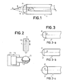
- FIG. 1 represents in section an optical fiber 1 provided with a coupling lens 2 intended to improve the coupling between the fiber and a light source placed at a point A which is considered first of all located on the x axis of FIG. 1.
- the coupling lens 2 is produced on the end of the fiber 1 facing point A and forming a planar surface P perpendicular to the x axis.
- the source placed at A emitting a divergent beam 5 of half-angle at the apex 6, the lens 2 converges this beam towards the input face P. Only part of the beam fulfills the conditions of propagation in the core 3 of the fiber . One of the spokes fulfilling these conditions has been shown in the figure.
- the fiber 1 is intended to be connected to another fiber with digital aperture lower, it is the latter which is to be taken into account for the actual coupling conditions.
- the improvement of the coupling, brought by the lens, consists in an increase in the fraction of coupled radiation, due to the operated convergence.
- the lens 2 is a plano-convex lens forming a spherical cap whose center O is located on the x axis. It is formed in a transparent material having a refractive index n significantly higher than those of the core 3 and the sheath 4 of the fiber.
- n refractive index
- the choice of a high index will be justified in the following description. It has indeed been demonstrated and experimentally observed that, whatever the light source to be coupled, the coupling coefficient is all the greater the higher the index n.
- the choice of the material to be used was guided by the properties of adhesion, mechanical strength, and especially by the values of refractive index and melting temperature. This is how we are led to choose a glass rather than a plastic. The choice of glass ensures a certain structural continuity between the lens and the fiber, whether it is glass or silica.
- Figure 2 shows the main elements of a device for depositing the spherical glass cap on the prepared end of the fiber 1.
- the latter is maintained and positioned by a movable support 10, preferably in a vertical position.
- a drop of molten glass 11 is retained in a heating filament 12 carried by a filament holder 13 which is also mobile.
- the shape of the filament is very important because it determines the shape of the glass drop 11, which also depends on gravity.
- the x-axis of the fiber must be perfectly centered relative to the filament. Its verticality ensures a symmetry of revolution.
- the temperature of the molten glass is between the pasty state and the start of decomposition. It is very important that it is lower than the softening temperature of the fiber. Low melting temperature and high index are often linked for glass. This fact avoids the disadvantages of the known technique of creating the spherical cap by melting the end of the fiber: migration of material towards the end, risking dust or inhomogeneities, impossibility of obtaining optimal coupling for any fiber due to the different nature of the core and cladding materials. Choosing a low temperature also allows the use of simple equipment for implementing the process.
- the process of the invention has been tried essentially with three types of glass whose refractive indices for a wavelength of 8521 A and the transformation temperature are respectively 1.88 - 396 °, 1.60 - 432 ° C , 1.48 - 464 ° C.
- the desired temperature is obtained by adjusting the intensity of the electrical supply 14 of the filament.
- the low temperature values required make it possible to use advantageously for the realization of the invention a Fonbrune microforge, usually used for the manufacture of micro-tools.
- a material can be used for the filament whose melting temperature is not very high.
- the filament can be, for example, in rhodium-plated platinum at 30% which melts at 1910 °.
- the shape of the spherical cap in particular the position of its center, depend on controllable parameters which are the temperature of the molten glass, the speeds of approach and distance of the fiber compared to the heating filament and the temperature variations as well obtained.
- FIG. 3 represents 3 types of caps which can be obtained with different deposition conditions.
- the cap is hemispherical, that is to say that its center O is located in the plane P.
- the center O is located inside the fiber.
- the center O is located between point A and the end of the fiber.
- the method of the invention makes it possible to obtain any form of lens (position of the center, diameter). It therefore allows optimization of the coupling, as can be determined by calculation and verified by experience.
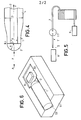
- the parameters necessary for this optimization are defined in FIG. 4 for a hemispherical lens. These are the diameter d of the core, the radius R of the hemisphere, the distance X + R between point A and the center O, the index n of the lens and the numerical aperture ON of the fiber .
- R 40 ⁇ m
- X 37 f m
- sine 0.51
- X 34 ⁇ m
- sin ⁇ 0.52.
- this value of R is equal to half the diameter of the sheath in the vicinity of the end. Most often, it does not correspond to that of the sheath diameter D of the fiber used, which is generally larger. It is therefore possible either to decrease the diameter of the fiber by chemical attack to obtain the optimal value, or to keep the fiber intact and to be satisfied with non-optimized values. The choice depends on the requirements that have been set.
- the diameter is reduced at the end by chemical attack in a solution of hydrofluoric acid.
- a 40% solution is used and the sheath is attacked over about 1 cm in length.
- the operation can be done at room temperature.
- hydrofluoric acid attacks the core of the fiber as a priority, so that, in the absence of special precautions, the surface obtained is not planar but constitutes a divergent lens, which harms coupling.
- it is preferable to protect it with a wax that one then remove.
- the speed of attack of the sheath being known (approximately 1 m per minute), one can determine the duration necessary.
- a permanent control of the diameter can be carried out. Once the desired diameter is reached, the fiber is rinsed, and it is then that its end is prepared by breaking, as indicated above.
- the fraction of power coupled with respect to the available power of the laser P E is of the order of 0.7.
- the laser 6 is placed on a mobile support in rotation about an axis perpendicular to the plane of the junction, and mobile in translation along three perpendicular axes x, y, z.
- the connecting fiber 7 is wound and measures around 600 m. Its attenuation is around 2.6 dB / km, which gives a total attenuation of 1.56 dB and a transmission coefficient of 0.7. Its numerical aperture is 0.18.
- magnesium fluoride with an index of 1.38, is particularly suitable. Layers of magnesium fluoride of controlled thickness were therefore deposited by vacuum evaporation on the lenses produced. A further improvement in attenuation of about 0.6 dB has been seen.
- FIG. 6 An example of a positioning support enabling the indicated tolerance values to be reached is shown in FIG. 6. It is a copper base 51 in which a V-shaped groove 52 has been made. To obtain sides Plans with precise tilt, it is advantageous to use the process de scribes in the french patent application filed by the applicant May 18, 1978 under the number "78 14 763 and published under No. 2 426 271. Indeed , according to this method, the groove 52 reproduces in negative a dihedral formed by chemical attack of monocrystalline silicon, attack which is carried out preferably along axes of the crystal. At the same time as the groove 52, an imprint 53 is made forming a flat area intended to serve as a seat for the semiconductor laser. It is welded to this zone 53 of the base, so that its successive layers are parallel to the plane.
- the optical fiber 1 prepared and produced according to the method described above, is placed in the groove 52.
- the imprint 53 and the groove 52 are provided according to the structure of the laser wafer and the diameter of the fiber so that the active layer of the laser is in the diametrical plane of the fiber.
Landscapes
- Physics & Mathematics (AREA)
- General Physics & Mathematics (AREA)
- Optics & Photonics (AREA)
- Engineering & Computer Science (AREA)
- Plasma & Fusion (AREA)
- Optical Couplings Of Light Guides (AREA)
- Optical Fibers, Optical Fiber Cores, And Optical Fiber Bundles (AREA)
- Instruments For Viewing The Inside Of Hollow Bodies (AREA)
Applications Claiming Priority (2)
| Application Number | Priority Date | Filing Date | Title |
|---|---|---|---|
| FR7922886 | 1979-09-13 | ||
| FR7922886A FR2465238A1 (fr) | 1979-09-13 | 1979-09-13 | Dispositif de couplage entre une source lumineuse a rayonnement divergent et une fibre optique et procede de realisation d'un tel dispositif |
Publications (1)
| Publication Number | Publication Date |
|---|---|
| EP0025728A1 true EP0025728A1 (fr) | 1981-03-25 |
Family
ID=9229623
Family Applications (1)
| Application Number | Title | Priority Date | Filing Date |
|---|---|---|---|
| EP80401187A Ceased EP0025728A1 (fr) | 1979-09-13 | 1980-08-13 | Dispositif de couplage entre une source lumineuse à rayonnement divergent, et une fibre optique, et procédé de réalisation d'un tel dispositif |
Country Status (4)
| Country | Link |
|---|---|
| EP (1) | EP0025728A1 (index.php) |
| JP (1) | JPS5647018A (index.php) |
| CA (1) | CA1143977A (index.php) |
| FR (1) | FR2465238A1 (index.php) |
Cited By (9)
| Publication number | Priority date | Publication date | Assignee | Title |
|---|---|---|---|---|
| FR2502796A1 (fr) * | 1981-03-27 | 1982-10-01 | Thomson Csf | Micro-optique de couplage entre un laser semi-conducteur et une fibre optique |
| EP0114439A1 (en) * | 1982-12-23 | 1984-08-01 | Koninklijke Philips Electronics N.V. | Monomode optical transmission fibre having a tapered end portion and method of manufacturing such a fibre |
| EP0355200A1 (en) * | 1988-08-12 | 1990-02-28 | Advanced Cardiovascular Systems, Inc. | Balloon dilatation catheter with laser cutting capability |
| GB2227103A (en) * | 1989-01-11 | 1990-07-18 | Masahiko Hoshino | Laser apparatus for medical treatment |
| EP0573744A1 (de) * | 1992-06-12 | 1993-12-15 | Richard Hirschmann GmbH & Co. | Verfahren und Vorrichtung zur Bearbeitung von Lichtwellenleiter-Endflächen |
| GB2286899A (en) * | 1994-02-28 | 1995-08-30 | Eev Ltd | Plano-convex lens for an optical fibre |
| US5495545A (en) * | 1994-10-24 | 1996-02-27 | International Business Machines Corporation | Method for extending bandwidth of large core fiber optic transmission links |
| US5504828A (en) * | 1994-06-29 | 1996-04-02 | International Business Machines Corporation | Apparatus for extending bandwidth of large core fiber optic transmission links |
| WO2004055563A1 (en) * | 2002-12-13 | 2004-07-01 | Corning Incorporated | Lensed fiber for optical interconnections |
Families Citing this family (1)
| Publication number | Priority date | Publication date | Assignee | Title |
|---|---|---|---|---|
| JPH0643772Y2 (ja) * | 1987-06-15 | 1994-11-14 | 旭光学工業株式会社 | 内視鏡のライトガイドコネクタ |
Citations (3)
| Publication number | Priority date | Publication date | Assignee | Title |
|---|---|---|---|---|
| US3843865A (en) * | 1971-09-14 | 1974-10-22 | G Nath | Device for material working by a laser beam,and method for its production |
| US4137060A (en) * | 1977-07-18 | 1979-01-30 | Robert Bosch Gmbh | Method of forming a lens at the end of a light guide |
| FR2399675A1 (fr) * | 1977-08-01 | 1979-03-02 | Consiglio Nazionale Ricerche | Dispositif de transmission et de focalisation d'une radiation laser au moyen d'une fibre optique |
-
1979
- 1979-09-13 FR FR7922886A patent/FR2465238A1/fr active Granted
-
1980
- 1980-08-13 EP EP80401187A patent/EP0025728A1/fr not_active Ceased
- 1980-09-12 JP JP12614380A patent/JPS5647018A/ja active Pending
- 1980-09-12 CA CA000360166A patent/CA1143977A/en not_active Expired
Patent Citations (3)
| Publication number | Priority date | Publication date | Assignee | Title |
|---|---|---|---|---|
| US3843865A (en) * | 1971-09-14 | 1974-10-22 | G Nath | Device for material working by a laser beam,and method for its production |
| US4137060A (en) * | 1977-07-18 | 1979-01-30 | Robert Bosch Gmbh | Method of forming a lens at the end of a light guide |
| FR2399675A1 (fr) * | 1977-08-01 | 1979-03-02 | Consiglio Nazionale Ricerche | Dispositif de transmission et de focalisation d'une radiation laser au moyen d'une fibre optique |
Cited By (11)
| Publication number | Priority date | Publication date | Assignee | Title |
|---|---|---|---|---|
| FR2502796A1 (fr) * | 1981-03-27 | 1982-10-01 | Thomson Csf | Micro-optique de couplage entre un laser semi-conducteur et une fibre optique |
| EP0063504A1 (fr) * | 1981-03-27 | 1982-10-27 | Thomson-Csf | Micro-optique de couplage entre un laser semi-conducteur et une fibre optique |
| EP0114439A1 (en) * | 1982-12-23 | 1984-08-01 | Koninklijke Philips Electronics N.V. | Monomode optical transmission fibre having a tapered end portion and method of manufacturing such a fibre |
| EP0355200A1 (en) * | 1988-08-12 | 1990-02-28 | Advanced Cardiovascular Systems, Inc. | Balloon dilatation catheter with laser cutting capability |
| GB2227103A (en) * | 1989-01-11 | 1990-07-18 | Masahiko Hoshino | Laser apparatus for medical treatment |
| GB2227103B (en) * | 1989-01-11 | 1993-04-14 | Masahiko Hoshino | Laser apparatus for medical treatment |
| EP0573744A1 (de) * | 1992-06-12 | 1993-12-15 | Richard Hirschmann GmbH & Co. | Verfahren und Vorrichtung zur Bearbeitung von Lichtwellenleiter-Endflächen |
| GB2286899A (en) * | 1994-02-28 | 1995-08-30 | Eev Ltd | Plano-convex lens for an optical fibre |
| US5504828A (en) * | 1994-06-29 | 1996-04-02 | International Business Machines Corporation | Apparatus for extending bandwidth of large core fiber optic transmission links |
| US5495545A (en) * | 1994-10-24 | 1996-02-27 | International Business Machines Corporation | Method for extending bandwidth of large core fiber optic transmission links |
| WO2004055563A1 (en) * | 2002-12-13 | 2004-07-01 | Corning Incorporated | Lensed fiber for optical interconnections |
Also Published As
| Publication number | Publication date |
|---|---|
| CA1143977A (en) | 1983-04-05 |
| FR2465238A1 (fr) | 1981-03-20 |
| FR2465238B1 (index.php) | 1983-03-04 |
| JPS5647018A (en) | 1981-04-28 |
Similar Documents
| Publication | Publication Date | Title |
|---|---|---|
| EP0061378B1 (fr) | Procédé de modification contrôlée des caractéristiques géométriques de l'extrémité d'une fibre optique monomode, et application au couplage optique | |
| EP0005683B1 (fr) | Procédé pour former sur au moins l'une des faces d'extrémités d'une fibre optique une microlentille plan-convexe accolée par sa face plane contre ladite face d'extrémité | |
| FR3066615B1 (fr) | Puce photonique a structure de collimation integree | |
| EP0674198B1 (fr) | Procédé de réalisation d'un composant de raccordement à une fibre multicoeurs | |
| EP0825464B1 (fr) | Procédé de fabrication et d'assemblage d'un dispositif de couplage optique collectif sur l'extrémité d'un faisceau de plusieurs fibres optiques monomodes | |
| EP0603042A1 (fr) | Système optique monolithique de couplage entre une fibre optique et composant électrooptique | |
| EP2267500A2 (fr) | Structure et procédé d'alignement d'une fibre optique et d'un guide d'ondes submicronique | |
| EP0025728A1 (fr) | Dispositif de couplage entre une source lumineuse à rayonnement divergent, et une fibre optique, et procédé de réalisation d'un tel dispositif | |
| EP0677758B1 (fr) | Système optique pour coupler une fibre à mode circulaire et un phototransducteur à mode elliptique et son procédé de fabrication | |
| FR2699292A1 (fr) | Procédé de préparation par lentillage multiple d'une fibre optique en vue d'un couplage optimum avec un phototransducteur et système optique obtenu. | |
| EP0715192A1 (fr) | Procédé de couplage entre une fibre optique multicoeurs et plusieurs fibres optiques monocoeurs | |
| EP0086155B1 (fr) | Procédé de polissage d'une fibre optique, application à la réalisation de dispositifs de couplage optique | |
| EP3389097B1 (fr) | Photodiode | |
| EP1499916A1 (fr) | Dispositif de couplage optoelectronique perfectionne | |
| EP3968066A1 (fr) | Guide d'onde comportant une fibre optique multimode et adapte a concentrer spatialement les modes guides | |
| EP0286475B1 (fr) | Procédé de modification du coefficient de réflexion de l'extrémité d'une fibre optique monomode et interféromètre à fibre optique réalisé à l'aide de ce procédé | |
| FR2559591A1 (fr) | Procede de realisation d'une micro-optique sur une extremite de fibre optique | |
| FR2734914A1 (fr) | Procede de fabrication d'une lentille souple a l'extremite d'une fibre optique | |
| FR2860599A1 (fr) | Dispositif de couplage optique d'une fibre monomode multi-coeurs, et procede de fabrication correspondant | |
| EP0587496A1 (fr) | Procédé de préparation du raccordement, et procédé de raccordement par épissurage d'un dispositif d'optique integrée à un câble optique, et sous-ensembles de raccordement pour la mise en oeuvre de ce procédé | |
| FR2490045A1 (fr) | Dispositif d'emission-reception d'energie radiante et systeme de liaisons bidirectionnelles par fibres optiques mettant en oeuvre un tel dispositif | |
| FR2763138A1 (fr) | Guide optique muni en son extremite d'une lentille souple et procede de fabrication de celle-ci | |
| EP0582640A1 (fr) | Matrice de concentrateurs optiques, ensemble optique comportant une telle matrice et procede de fabrication de la matrice | |
| WO2009118484A2 (fr) | Sous-ensemble optoelectronique | |
| FR3057675A1 (fr) | Procede de fabrication d'un guide d'onde |
Legal Events
| Date | Code | Title | Description |
|---|---|---|---|
| PUAI | Public reference made under article 153(3) epc to a published international application that has entered the european phase |
Free format text: ORIGINAL CODE: 0009012 |
|
| AK | Designated contracting states |
Designated state(s): DE GB IT NL SE |
|
| 17P | Request for examination filed |
Effective date: 19810404 |
|
| STAA | Information on the status of an ep patent application or granted ep patent |
Free format text: STATUS: THE APPLICATION HAS BEEN REFUSED |
|
| 18R | Application refused |
Effective date: 19820723 |
|
| RIN1 | Information on inventor provided before grant (corrected) |
Inventor name: JACQUES, ANDRE Inventor name: COMBEMALE, YVES Inventor name: D'AURIA, LUIGI Inventor name: RICHIN, PHILIPPE |