EP0025614A1 - Verfahren und Apparat zur ununterbrochenen Bestimmung einer Zeitspanne, in welcher eine Handlung ausgeführt werden soll - Google Patents
Verfahren und Apparat zur ununterbrochenen Bestimmung einer Zeitspanne, in welcher eine Handlung ausgeführt werden soll Download PDFInfo
- Publication number
- EP0025614A1 EP0025614A1 EP80200716A EP80200716A EP0025614A1 EP 0025614 A1 EP0025614 A1 EP 0025614A1 EP 80200716 A EP80200716 A EP 80200716A EP 80200716 A EP80200716 A EP 80200716A EP 0025614 A1 EP0025614 A1 EP 0025614A1
- Authority
- EP
- European Patent Office
- Prior art keywords
- aircraft
- speed
- runway
- predetermined
- maximum
- Prior art date
- Legal status (The legal status is an assumption and is not a legal conclusion. Google has not performed a legal analysis and makes no representation as to the accuracy of the status listed.)
- Withdrawn
Links
- 230000009471 action Effects 0.000 title claims abstract description 80
- 238000000034 method Methods 0.000 title claims abstract description 33
- 230000008859 change Effects 0.000 claims abstract description 60
- 230000000063 preceeding effect Effects 0.000 claims 1
- 230000002452 interceptive effect Effects 0.000 abstract description 4
- 238000010586 diagram Methods 0.000 description 25
- 230000007704 transition Effects 0.000 description 12
- 230000001133 acceleration Effects 0.000 description 10
- 230000000694 effects Effects 0.000 description 10
- 238000012544 monitoring process Methods 0.000 description 8
- 238000000926 separation method Methods 0.000 description 8
- 230000006870 function Effects 0.000 description 4
- 230000033001 locomotion Effects 0.000 description 4
- 230000003247 decreasing effect Effects 0.000 description 3
- 230000009467 reduction Effects 0.000 description 3
- 230000002829 reductive effect Effects 0.000 description 3
- 240000007320 Pinus strobus Species 0.000 description 2
- 230000006399 behavior Effects 0.000 description 2
- 239000000872 buffer Substances 0.000 description 2
- 239000000446 fuel Substances 0.000 description 2
- 239000000203 mixture Substances 0.000 description 2
- 230000004044 response Effects 0.000 description 2
- 230000001960 triggered effect Effects 0.000 description 2
- 101100521334 Mus musculus Prom1 gene Proteins 0.000 description 1
- 238000004364 calculation method Methods 0.000 description 1
- 238000006243 chemical reaction Methods 0.000 description 1
- 239000002131 composite material Substances 0.000 description 1
- 238000005094 computer simulation Methods 0.000 description 1
- 230000007423 decrease Effects 0.000 description 1
- 230000003111 delayed effect Effects 0.000 description 1
- 230000001419 dependent effect Effects 0.000 description 1
- 230000010006 flight Effects 0.000 description 1
- 231100001261 hazardous Toxicity 0.000 description 1
- 230000000670 limiting effect Effects 0.000 description 1
- 230000036961 partial effect Effects 0.000 description 1
- 230000002093 peripheral effect Effects 0.000 description 1
- 230000003068 static effect Effects 0.000 description 1
Images


Classifications
-
- G—PHYSICS
- G05—CONTROLLING; REGULATING
- G05D—SYSTEMS FOR CONTROLLING OR REGULATING NON-ELECTRIC VARIABLES
- G05D1/00—Control of position, course, altitude or attitude of land, water, air or space vehicles, e.g. using automatic pilots
- G05D1/0083—Control of position, course, altitude or attitude of land, water, air or space vehicles, e.g. using automatic pilots to help an aircraft pilot in the rolling phase
-
- B—PERFORMING OPERATIONS; TRANSPORTING
- B64—AIRCRAFT; AVIATION; COSMONAUTICS
- B64C—AEROPLANES; HELICOPTERS
- B64C25/00—Alighting gear
- B64C25/32—Alighting gear characterised by elements which contact the ground or similar surface
- B64C25/42—Arrangement or adaptation of brakes
- B64C25/426—Braking devices providing an automatic sequence of braking
Definitions
- the present invention relates to methods and apparatus for determining the occurrence of events and, more particularly, methods and apparatus for achieving a desired objective related to such events.
- the present invention was developed for use on board aircraft to assist the pilot in achieving a desired objective, and is described in such an environment, it is to be understood that the invention is also useful in other environments, particularly vehicular environments to provide a similar result.
- the term "desired objective” covers a multitude of objectives, including both the avoidance of potentially hazardous incidents (e.g., an aircraft not stopping or not taking off before reaching the end of a runway) and the achievement of desirable results (such as an aircraft's speed dropping to a desired value when a particular exit ramp is reached after a landing).
- Warning and caution signals designed to assist a pilot in accomplishing a safe flight from takeoff to landing.
- the warning and caution signals are designed to advise the pilot of the occurrence of a condition that could prevent the achieving of a safe flight. While it is difficult to establish an exact definition of the difference between warning and caution signals, the most common definition appears to be that a warning signal signifies a condition to which a relatively immediate response must be made, and a caution signal is one to which a response may be safely delayed for some time period. In either case, warning and caution signals advise the pilot that a particular condition has occurred that may have an effect on the accomplishment of a safe flight between takeoff and landing.
- Another situation currently requiring pilot judgment is the rejected "take- off" situation. This situation is particularly difficult to judge if it is precipitated by trouble other than engine failure.
- Current procedure uses indicated airspeed as a go/stop criterion in rejected take-off situations. This criterion is adequate if engine failure is the cause of the refused take-off situation, but inadequate if the refused take-off situation is caused by other factors.
- An indication to the pilot of whether or not a safe take-off and/or a safe stop can be achieved under a wide variety of existing conditions would greatly enhance the pilot's ability to make the correct judgment.
- a further situation is one wherein the aircraft is sinking on approach and a determination must be made to either attempt to land or "go-around" and make another landing approach. An indication to the pilot of whether or not a safe landing and/or a safe go-around can be achieved under existing conditions would also greatly enhance the pilot's ability to make the correct judgment.
- a method of and an apparatus for providing a pilot with interactive information adapted to assist him in making the proper judgment under many situations by providing him with an indication of the time in which action must be taken in order to accomplish a desired objective is desirable.
- Such a method and apparatus that can be alternatively used to automatically control certain aspects of an aircraft to achieve the desired objective is also desirable.
- the interval of time in which action must be taken to achieve a desired objective is herein denoted the chronodrasic interval.
- the word chronodrasic is derived from Greek and means literally time for action (chronos--time, drasis--action).
- the present invention provides a method of determining the amount of a parameter remaining to take maximum control action to achieve a desired objective (e.g., the chronodrasic interval) comprising the steps of: determining the amount of a parameter required to achieve the desired objective if maximum control action is immediately applied; determining the amount of the parameter remaining; deducting the amount of the parameter requred to achieve the desired objective if maximum control action is immediately applied from amount of the parameter remaining; determining the present rate of change of the parameter; and dividing the result of deducting the amount of the parameter required to achieve the desired objective if maximum control action is immediately applied from the amount of the parameter remaining by the present rate of change of the parameter.
- a desired objective e.g., the chronodrasic interval
- the present invention also provides an apparatus for determining the time remaining to apply maximum velocity change action to change the velocity of a vehicle to a predetermined.value by the time the vehicle moves from its present position to a predetermined position, said apparatus comprising:
- the method and apparatus are based on the understanding that, in dynamic systems, the achievement of a desired objective requires that a derivative of a parameter attain a specific value before the parameter itself attains a specific value.
- the achievement of the objective of an aircraft stopping or taking off before reaching the end of a runway requires that the velocity of the aircraft (a derivative of distance) attain a specific value (zero or rotation speed) before the runway distance remaining reduces to zero.
- the method and apparatus of the present invention continuously determine the limiting or boundary case based on the application of the maximum control action available. That is, the method and apparatus continuously determines the amount of the parameter required to achieve the desired objective if maximum control action is immediately taken. In addition, the method and apparatus continuously determines the total amount of the parameter remaining. Then, the chronodrasic interval is determined by deducting the parameter amount required to achieve the desired objective if maximum control action is taken from the total amount of the parameter remaining; and, dividing the result by the present rate of change of the parameter.
- the value of the chronodrasic interval (preferably only if below a predetermined value) is displayed to provide interactive information adapted to apprise a human operator of the need to take control action and the effectiveness of the action taken.
- the value of the chronodrasic interval is used to automatically regulate the amount of control action taken.
- apparatus formed in accordance with the invention includes an electronic control system adapted to provide the chronodrasic interval information in signal form adapted to control either a display or an automatic control apparatus.
- the display apprises the operator of the necessity to take control action and the effectiveness of the control action taken.
- the signal forms a feedback signal that is used in a conventional manner to control the action taken. In either case, the signal is utilized to achieve the desired objective.
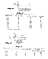
- FIGURE 1 comprises a line diagram illustrating an aircraft A on a runway R.
- a distance X o separates the aircraft from the end of the runway; and the aircraft is travelling toward the end of the runway at a present velocity X' 0 .
- the aircraft has a braking capability such that the average maximum deceleration that can be created is generally equal to ⁇ g, where ⁇ represents the coefficient of friction of the runway and g is the gravitational constant.
- maximum braking is actually represented by ⁇ g, minus the idle thrust - of the engines divided by the mass of the aircraft.
- ⁇ g represents the coefficient of friction of the runway
- g the gravitational constant
- the ⁇ g term can be replaced by fixed values depending upon the general condition of the runway, e.g., icy, wet or dry.
- ⁇ g can take on a fixed value of 2.5; in the case of a wet runway, ⁇ g can take on a fixed value of 6; and, in the case of a dry runway ⁇ g can take on a fixed value of 12.5.
- the chronodrasic interval is the time remaining for the pilot to apply maximum aircraft brake action in order to stop the aircraft by the time the end of the runway is reached.
- equation (1) As noted above, the average maximum acceleration available in a practical system can be equated to ⁇ g (or a constant), whereby PAR is equal to (X' 0 ) 2 /2 ⁇ g.
- equation (1) becomes: which can be reduced to:
- FIGURES 2A and 2B illustrate the time remaining (e.g., the chronodrasic interval) for brake application and elapsed time from the 2000 foot point, assuming the pilot takes no action, whereby the aircraft's velocity remains constant. In this case, the chronodrasic interval starts out at 38 seconds and linearly reduces to zero. It should be noted that the chronodrasic interval does not indicate when the aircraft will reach the end of the runway; rather it indicates how long the pilot has to apply maximum braking action to avoid running off the end of the runway.
- the chronodrasic interval reaches zero when the distance separating the aircraft from the end of the runway is 100 feet.
- the pilot applies maximum braking action prior to reaching the 100 foot separation point, he will be able to stop the aircraft before the end of the runway is reached.
- the aircraft will not stop by the time the end of the runway is reached.
- FIGURES 3A and 3B illustrate a situation where it is assumed that the pilot accelerates the aircraft at the 1500 foot separation point so that when the aircraft reaches the 1000 foot separation point, its speed is 100 feet per second, rather than 50 feet per second. Obviously as is clearly shown in FIGURES 3A and 3B, such acceleration substantially diminishes the chronodrasic interval. In fact, the chronodrasic interval changes quite rapidly during the period of acceleration between the 1500 and 1000 foot separation points; and, the increased velocity requires that maximum braking action be applied by the 400 foot separation point, rather than the 100 foot separation point, in order to avoid running off the end of the runway.
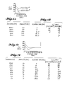
- FIGURES 4A and 4B illustrate the situation wherein the pilot exhibits a more rational behaviour and applies some brake force as he reaches the 1000 foot separation point.
- the speed schedule followed is illustrated in the second column of FIGURE 4B.
- FIGURE 4A graphically illustrates that with this speed schedule the chronodrasic interval does not fall below 18 seconds, even though the pilot stops only 50 feet from the end of the runway.
- the chronodrasic interval after dropping to 18 seconds remains around or slightly above 19 seconds due to the braking action applied (which is less than maximum available braking action) until the aircraft stops, at which time the chronodrasic interval becomes essentially infinite.
- FIGURES 5A, 5B; 6A, 6B; and 7A, 7B correspond to FIGURES 2A, 2B; 3A, 3B; and 4A, 4B, respectively, and show what occurs if the condition of the runway is such that only 2.5 feet per second 2 of deceleration is possible, rather than 12.5 feet per second 2 .
- This could represent an icy runway where g 2.5.
- FIGURES 5A, 6A and 7A include the graphical information contained in FIGURES 2A, 3A and 4A, respectively, plus a curve illustrating what occurs for a 2.5 feet per second 2 assumed maximum deceleration rate; and, FIGURES 5B, 6B and 7B show the same general information in table form, plus speed and distance information.
- the effect of changing brake effectiveness is not constant but depends on the speed of the aircraft. When the pilot of the aircraft applies brakes early as illustrated in FIGURE 7A, the effect of a five fold reduction in braking is hardly noticeable.
- FIGURES 5A, 5B; 6A, 6B; and, 7A, 7B could, for example, illustrate the situation wherein an aircraft is equipped with two sets of brakes--a main braking system and an auxiliary braking system.
- the figures illustrate the effect of a failure of the main braking sytem, assumed to have a braking capacity of 12.5 feet per second 2 , so that the auxiliary braking system, assumed to have a braking capacity of 2.5 feet per second 2 , is required to provide the full braking effect.
- these figures could illustrate a situation wherein the runway 4 1 factor varies from a dry pavement to an icy pavement.
- the chronodrasic interval is the interval during which control action can be taken to reach a desired objective. It is not the time to a particular event occurring. Thus, the lapse of the chronodrasic interval occurs simultaneously with the inability of maximum corrective action to avoid the event and, thereby, achieve the desired objective.
- the time interval between the end of the chronodrasic interval and the occurrence of the event is more appropriately called the chronagonic (agonizing time) interval.
- Aircraft movement is definable in terms of the first derivative of distance, i.e., velocity, plus any change resulting from accelerations or decelerations, which are the second derivative of distance. More specifically, aircraft movement distance is equal to the initial velocity X' 0 multiplied by the interval of movement, I, plus or minus the distance gained or lost respectively, as a result of the acceleration or deceleration of the aircraft --X" 0 (I) 2 /2, In other words:
- the interval I is broken into two intervals, I 1 and I 2 .
- I I is the chronodrasic interval and I 2 is the interval required for the aircraft to achieve its desired objective (e.g., stopping before reaching the end of the runway) if maximum control action (e.g., braking) is applied.
- maximum control action e.g., braking
- the invention answers the question: For the current ground speed, X' 0 , how long can the aircraft go (the chronodrasic interval I 1 ) before maximum control action must be applied in order to achieve the desired objective?
- the maximum control action is maximum braking.
- the maximum control action is the maximum thrust available, since reaching rotation velocity is the desired objective.
- the invention is based on the rate of change of the parameter, in this case current ground speed, X' 0 , remaining constant until maximum control action is applied.
- Maximum control action of course is the change in velocity due to deceleration (stopping) or acceleration (take-off). Since the assumption is being made that the rate of change of the parameter will remain constant during the chronodrasic interval, I l , that term vanishes from the portions of equations (6) and (7) related to changes in the rate of change of the parameter (i.e., the acceleration or deceleration terms), whereby these equations respectively become:
- Equations (8) and (9) are the two basic equations that describe the operation of the invention. These equations not only apply to an aircraft or other vehicle moving along a runway, course or track, they apply to any type of dynamic system having a parameter related to a desired objective that can be subjected to some maximum control action to achieve the desired objective, as long as the value of the parameter, the rate of change of the parameter and changes in the rate of change of the parameter can be measured or calculated.
- equations (8) and (9) show that, in dynamic systems, the achievement of a desired objective (such as an aircraft stopping before reaching the end of a runway on landing or an aircraft reaching rotation speed before reaching the end of a runway on takeoff) requires that the rate of change or derivative (e.g., velocity) of a parameter (e.g., distance) attain a specific value before the parameter itself contains a specific value.
- a desired objective such as an aircraft stopping before reaching the end of a runway on landing or an aircraft reaching rotation speed before reaching the end of a runway on takeoff
- Equation (13) does not take into consideration the sign of the various components.
- X' 0 is always a negative number since the runway length is decreasing in value.
- X" 0 is a positive number since its direction is toward increasing X 0 .
- equation (14) is in the form of equation (1). That is, equation (14) states that the chronodrasic interval (I 1 ) is equal to the amount of the parameter remaining (X 0 ) minus the amount of the parameter required to achieve the desired objective [(X' 0 ) 2 /2X" 0 ] ] divided by the rate of change of the parameter (X' 0 ).
- equation (14) is the basic expression for this particular environment of application of the invention, equation (14) can be further simplified for computation purposes. The result is:
- equation (15) is the least complicated expression that defines the chronodrasic interval for an aircraft landing situation where it is desired to stop the aircraft by the time the end of the runway is reached.
- equation (15) is the least complicated expression that defines the chronodrasic interval for an aircraft landing situation where it is desired to stop the aircraft by the time the end of the runway is reached.
- a similar mathematical exercise can be performed to determine the chronodrasic interval if it is desired that the speed of the aircraft be reduced to some predetermined value (greater than zero) at some point prior to the end of the runway, such as a turnoff ramp intersection point.
- the chronodrasic interval formula becomes: where: X TO is equal to the runway length to the turn- off point;
- Equation (16) can be reduced to: for computation purposes.
- equations (15) and (17), X" 0 can be replaced by ⁇ g, where ⁇ is the coefficient of friction of the runway and g is the gravitational constant.
- equations (15) and (17), respectively can be changed to the following:
- equations (18) and (19) can be further simplified by replacing ⁇ g with a constant whose value is related to the general condition of the runway, i.e., dry, wet or icy.
- the value of the chronodrasic interval, I 1 is continuously determined in accordance with equations (14) or (16), or the simplified versions thereof described above.
- the chronodrasic interval, I 1 may be continuously changing if, for example, the velocity of the aircraft remains unchanged or the velocity of the aircraft is changed in a manner such that the chronodrasic interval changes.
- the braking action can be such that the chronodrasic interval remains constant as the aircraft proceeds down the runway.
- the pilot can be made aware of the effect of any control action (e.g., brake application) he is taking.
- the chronodrasic interval if suitably displayed, continuously advises the pilot of the effectiveness of the control action he is taking.
- the value of the chronodrasic interval can be used to automatically control the application of the control action, i.e., brake pressure.
- the method of the invention generally comprises the steps of: determining the amount of a parameter required to achieve a desired objective if maximum control action is taken; determining the total amount of the parameter remaining; deducting the amount of the parameter required to achieve the desired objective if maximum control action is taken from the amount of the parameter remaining; and dividing the result by the present rate of change of the parameter.
- the parameter is runway length and the present rate of change of the parameter is the present velocity of the aircraft.
- Apparatus functioning in accordance with the foregoing method for use onboard an aircraft to advise the pilot of the chronodrasic interval related to reducing aircraft velocity to a predetermined value at a ramp intersection or, if that objective is not desired or cannot be achieved, advise the pilot of the chronodrasic interval related to stopping the aircraft before reaching the end of the runway is next described.
- FIGURE 8 is a line diagram showing the flight path of an aircraft landing on a runway so as to have available an initial objective of reducing its velocity to a predetermined value at the location of a runway ramp, X distance from the start of the runway, and thereafter the. objective of stopping the aircraft by the time the end of the runway is reached, the runway being X 0 feet in length.
- the landing flight path is illustrated as starting when the aircraft is fifty feet (50') above the start of the runway.
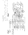
- FIGURE 9 is a block diagram of a chronodrasic monitoring system formed in accordance with the invention for producing a display suitable for providing interactive information for the pilot to use in applying brake power to achieve either of the two desired objectives.
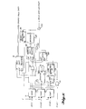
- FIGURE 10 is a block diagram of a ground speed data subsystem suitable for providing ground speed data for use in the . system illustrated in FIGURE 9.
- FIGURE 11 is a timing diagram useful in understanding the operation of the ground speed data subsystem illustrated in FIGURE 10; and
- FIGURES 12-16 are flow diagrams used to describe the operation of a data processor illustrated in FIGURE 9, which functions in accordance with equations (18) and (19) to control the display.
- the chronodrasic monitoring system illustrated in FIGURE 9 comprises: runway length switches 21; runway length to turnoff switches 23; r switches 25; turnoff speed switches 27; first, second, third and fourth input/output (I/O) interfaces 29, 31, 33 and 35 controlled by a first I/O selector 37; a 50' detector 39; a ground speed interface 41; a controller 43; a data processor 45; a clock 47; a random access memory (RAM) 49; a read only memory (ROM) 51; address buffers 53; a decoder 55; a fifth I/O interface 57 controlled by a second I/O selector 50; and a display 61.
- the runway length, runway length to turn- off, P and turnoff speed switches 21, 23, 25 and 27 are all thumbwheel actuated switches that display decimal numbers and control related signals in binary coded decimal (BCD) form.
- the runway length and runway length to turnoff switches 21 and 23 are five digit switches and the P and turnoff speed switches 25 and 27 are two digit switches.
- the BCD outputs of the runway length, runway length to turnoff, u and turnoff speed switches 21, 23 and 27 are connected to the inputs of the first, second, third and fourth I/O interfaces 29, 31, 33 and 35, respectively.
- the 50' detector 39 continuously receives altimeter data from the aircraft's altimeter. Upon reaching the 50 foot point, the voltage level of the output of the 50' detector 39 changes. This level change is detected by the controller 43 and initiates the operation of the chronodrasic monitor system. The level change is also applied to strobe inputs of the first, second, third and fourth I/O interfaces 29, 31, 33 and 35 to cause the interfaces to react and store the settings of their related switches. Further, the level change is detected by and enables the ground speed interface 41.
- the first, second, third and fourth I/O interfaces 29, 31, 33 and 35 also separately receive an enabling control input from the first I/O selector 37.
- the outputs of the first, second, third and fourth I/O interfaces 29, 31, 33 and 35 are connected to a common data bus 63.
- the first I/O selector 37 enables one and only one of the first, second, third and fourth I/O interfaces at a time so that one and only one of the runway length, runway length to turn off, and turn off speed switch data is applied to the data bus 63 at a time.
- the data processor 45 produces address signals that are applied to an address bus 65.
- the first I/O selector 37 receives the address signals produced by the data processor 45, via the address bus. If the address on the address bus is one designed to enable one of the first-fourth I/O interfaces, the first I/O selector enables the appropriate I/O interface. As a result, the related switch setting data is applied to the data bus in BCD form.
- the ground speed interface 41 receives and forwards ground speed data produced by the ground speed data subsystem illustrated in FIGURE 10 and'hereinafter described and applies that data to the data bus 63.
- the ground speed data subsystem produces a VALID DATA INTERRUPT signal that is applied to the data processor 45 when valid ground speed data is available.
- the controller 43 is connected to the data bus 63 and to the data processor 45 and acts as an interface therebetween.
- the data processor in addition to being connected to the controller 43, is also connected to the address bus 65, which extends to the second I/O selector 59; and, to the RAM 49 and the decoder 55 via the address buffers 53.
- the RAM 49 receives memory read and write control signals from the controller 43 and is connected to the data bus 63.
- the decoder 55 receives the read control signal produced by-the controller 43 and selected address bits; and, in accordance therewith, addresses the ROM.
- the ROM 51 is also connected to the data bus 63.
- the fifLh I/O interface 57 is connected between the data bus 63 and the display 61.
- the second I/O selector 59 produces an enable output that is applied to the enable input of the fifth I/O interface 57, when a suitable address is placed on the address bus 65 by the data processor 45.
- the pilot sets the runway length switches 21 to the length of the runway (X 0 ) on which he is to land and the runway length to turnoff switches 23 to the appropriate value (X TO ).
- the p switches 25 are set to the value of the runway ⁇ factor, which is supplied by the airport and the turnoff speed switches 27 are adjusted to the desired turnoff speed (X' T0 ).
- a transponder could be located at the end of the runway and used to transmit runway legnth, runway length to turn-off and ⁇ data to the aircraft upon being interrogated when the aircraft reaches the 50 foot (or some other chosen altitude) point.
- the turnoff speed could be automatically read from a memory, such data being based on the characteristics of the airfield with which the invention is being used and any other relevant criteria, such as runway p .
- the 50' detector applies a level change to the controller.
- the same level change strobes the first, second, third, and fourth I/O interfaces causing them to read and store their respective switch settings.
- the controller causes the data processor to sequentially produce the addresses of the first, second, third and fourth I/O interfaces on the address bus 65.
- the first I/O selector 37 sequentially enables the first, second, third and fourth I/O interfaces 29, 31, 33 and 35.
- runway length, runway length to turnoff, ⁇ and turn- off speed data are sequentially placed on the data bus 63.
- the RAM is addressed and enabled to receive and store the available data in a suitable data bin. As a result, data is transferred from the switches to the RAM at the start of the runway.
- the ground speed data subsystem illustrated in FIGURE 10 and hereinafter described produces ground speed data.
- a VALID DATA INTERRUPT pulse causes the data processor to forward the available data via the controller and the data bus to the RAM by enabling the ground speed interface 41; and, then addressing the RAM so that it receives and stores the data in a suitable data bin. Constants such as 2 and g are stored in the ROM. After all necessary data has been received and stored, the data processor determines the value of the chronodrasic interval in accordance with equations (18) or (19) as hereinafter described. As needed, the stored data is readout and used.
- the clock 47 produces timing pulses, which are applied to the data processor 45.
- the clock 47 also produces a reset pulse that resets the data processor and the hereinafter described ground speed data subsystem when a manually operated momentary contact switch is closed.
- the reset pulse also is used to reset other components that require resetting, such as the I/O interfaces. For purposes of clarity of illustration, wires for carrying reset pulses to such items are not illustrated.
- While the chronodrasic monitoring system illustrated in FIGURE 9 can be formed of components produced by various manufacturers, by way of example only, one actual embodiment of such a system was formed of components manufactured by the Intel Corporation of Santa Clara, California.
- the I/O interfaces 29, 31, 33, 35 and 57 were formed by 8212 8-bit Input/Output Ports; the I/O selectors 37 and 59 and the decoder 55 were formed by 8205 High-Speed 1-out-of-8 Binary Decoders;
- the data processor 45 was formed by a 8080A Single Chip 8-bit N-Channel Microprocessor;
- the controller 43 was formed by a 8228 System Controller and Bus Driver for 8080A CPU;
- the RAM 49 was formed by plurality of 8111A 256 x 4-bit static RAMs;
- the ROM 51 was formed by a plurality of 8708 8K UV Erasable PROMs;
- the clock 47 was formed by a 8224 Clock Generator and Driver for 8080A CPU; and, the interface 41 was formed
- FIGURE 10 Prior to describing how the data processor functions to produce the chronodrasic interval signal applied to the display via the data bus and the fifth I/O interface 57, the ground speed data subsystem illustrated in FIGURE 10 is described. In addition-to FIGURE 20, attention is directed to the timing diagram illustrated in FIGURE 11.
- the ground speed data subsystem illustrated in FIGURE 10 comprises: three comparators 71, 73 and 75; a sync flip-flop 77, a sync monostable multivibrator 79; a counter 81; a latch 83; an address shift register 85; a decoder 87; a reset monostable multivibrator 89; and, a data shift register 91.
- the ground speed data subsystem illustrated in FIGURE 10 includes: a two-input NAND gate designated Gl; two two-input AND gates designated G2 and G3; and, two two-input OR gates designated G4 and G5.
- the ground speed data subsystem illustrated in FIGURE 10 receives serial ground speed data and timing signals from a suitable ground speed signal source meeting the ARINC (Aeronautical Radio, Incorporated) 561 standards.
- the serial ground speed data includes address data, which identifies the nature of the following serial data (e.g., ground speed) and the actual data.
- the timing signals include clock pulses and sync pulses. The clock and sync pulses and a representative ground speed data signal are illustrated on the first three lines of FIGURE 11, respectively.
- the ground speed data signal is applied to the first comparator 71, which compares the level of the received signal with a predetermined voltage level (V) in a conventional manner to square up the received signal and prevent noise from producing false information.
- the clock and sync pulses are applied to the second and third comparators 73 and 75 where they are compared with the same predetermined voltage level (V) to perform the same functions.
- the serial ground speed data output of the first comparator 71 is applied to the data input of both the address shift register 85 and the data shift register 91.
- the clock pulse output of the second comparator 73 is applied to the clock input of the data shift register, the data input of the counter 81, the clock input of the sync flip-flop 77 and one input of G2.
- the sync pulse output of the third comparator 73 is applied to both the J and K inputs of the sync flip-flop 77.
- the Q output of the sync flip-flop 77 is applied to the trigger input of the sync monostable multivibrator 79.
- the Q output of the sync monostable multivibrator 79 is applied to the clear input of the counter 81.
- the Q output of the sync monostable multivibrator 79 is applied to the reset input of the latch 83 and to one input of G4.
- the counter 81 has 1, 8 and 32 pulse count outputs that are utilized. When the counter counts one pulse, its one (1) pulse count output shifts high. Similarly, when eight pulses are counted, the eight (8) pulse count output shifts high and when 32 pulses are counted, the thirty two (32) pulse count output shifts high.
- the 1 and 8 pulse count outputs of the counter 81 are connected each to one input of G1.
- the 32 pulse count output of the counter 81 is connected to one input of G3.
- the output of Gl is connected to the set input of the latch 83.
- the Q output of the latch 83 is connected to the second input of G2 and the output of G2 is connected to the clock input of the address shift register 85.
- the parallel data output of the address shift register 85 is connected to the input of the decoder 87.
- the output of the decoder 87 is connected to the second input of G3 and to the trigger input of the reset monostable multivibrator 39.
- the Q output of the reset monostable multivibrator 89 is connected to one input of G5.
- the reset output of the data processor illustrated in FIGURE 9 is connected to the second input of G5.
- the output of G5 is connected to the clear output of the sync flip-flop 77 and to the clear input of the data shift register 91.
- the sync flip-flop is both clocked and cleared by a high-to-low transition of the received signal at its clock and clear inputs.
- the counter 81 counts a pulse on a high-to-low transition and is cleared on a low-to-high transition.
- the latch 83 is set and reset on high-to-low transitions.
- the address register 85 is cleared on a high-to-low transition and clocked on a low-to-high transition.
- the data shift register 91 is cleared on a high-to-low transition and clocked on a low-to-high transition.
- the clock pulses are a repeating.chain of 32 bits followed by a gap which may be formed by a 33rd bit.
- the ground speed data subsystem is internally reset during the gap period by the reset monostable multivibrator 89 in the manner hereinafter described, or by a reset pulse produced by the data processor.
- the sync flip-flop 77 is cleared.
- the sync flip-flop is set by the high-to-low clock pulse transition occurring in the middle of the gap.
- the syn monostable multivibrator is triggered. Triggering the sync monostable multivibrator clears the counter 81, which is connected to the Q output of the sync monostable multivibrator.
- the latch 83 is reset and the address shift register 85 (via G4) is cleared by the Q output of the sync monostable multivibrator 79.
- the latch 83 is reset, its Q output shifts from low to high whereby G2 is enabled.
- clock pulses are allowed to flow through G2 to the clock input of the address shift register 85.
- the address shift register 85 is clocked, it reads the data signal present on the output of the first comparator 71.
- the first portion of the composite data signal identifies the following data and, thus, forms the "address" of that data.
- the address when the following data is ground speed data is as illustrated on the left side of the third line of FIGURE 11. That is, it is assumed that the ground speed data address is an eight-bit address having a binary value 01010000.
- the decoder 87 decodes the output of the address shift register. If the appropriate eight-bit address is received by the address shift register 85, immediately upon receipt of the last bit, the output of the decoder 87 shifts from low-to-high and triggers the reset monostable multivibrator 89; and, at the same time, enables G3.
- the address shift register 85 While the address shift register 85 was receiving the address signal, the counter 81 was counting clock pulses. After receiving nine clock pulses, the 1 and 8 outputs of the counter 81 are both high whereby the output of the G1 shifts from high-to-low. When the output of G1 shifts from high-to-low, the latch 83 is reset. Consequently, G2 is disabled. As a result, the address shift register holds the address previously received, whereby the output of the decoder 87 remains high and G3 remains enabled.
- the address shift register was receiving the address bits
- the data shift register was also receiving the address bits.
- the address bits are cleared from the data shift register when the reset monostable multivibrator 89 is triggered by the output of the decoder 87 shifting from low-to-high. More specifically, triggering the reset monostable multivibrator 89 clears the sync flip-flop 77 and the data shift register 91 via G5.
- the data shift register 91 now starts to receive and store data bits related to ground speed. This data is contained in the next 24 bits. (although the ground speed data is contained in these bits, only bits 17 through 30 actually contain ground speed data, as shown in FIGURE 11.) At the end of the total 32 bit count cycle, the 32-bit output of the counter 81 shifts from low to high.
- both inputs of G3 are high, whereby a valid data interrupt pulse, which occurs on the ouptut of G3, is forwarded to the data processor.
- the valid data interrupt signal causes the chronodrasic monitoring system illustrated in FIGURE 9 to receive and store the ground speed data on the output of the data shift register.91 in the manner previously described. Thereafter, the cycle of operation of the ground speed data subsystem illustrated in FIGURE 10 repeats.
- ground speed data is continuously converted from the serial form in which it is received into parallel form suitable for use by the chronodrasic monitoring system illustrated in FIGURE 9.
- a valid data interrupt will occur at 50 millisecond intervals, since ground speed data is produced at 50 millisecond intervals by such a ground speed data source.
- FIGURE 12 is a flow diagram illustrating the operation of the data processor illustrated in FIGURE 9.
- the data processor cycles asking the question: "Has the 50 foot altitude point been reached yet?"
- the 50' detector 39 produces a pulse.
- this pulse is received and, thus, the foregoing question is answered in the affirmative, the data processor proceeds to the next steps illustrated in FIGURE 12.
- These are switch data loading steps. First the runway length switch data (X 0) is read and stored in a suitable bin in the RAM. Next, the runway length to turnoff switch data (X TO ) is read and stored in a suitable bin in the RAM. Next, the switch data is read and stored in a suitable bin in the RAM.
- the turnoff speed switch data (X' T0 ) is read and stored in a suitable bin in the RAM. Obviously the order of reading and storing can change, as desired.
- a timer is initialized. The timer is utilized by the data processor so that the display is only updated at one (1) second intervals, as will be better understood from the following discussion.
- the data processor idles until a VALID DATA INTERRUPT pulse is received from the ground speed data subsystem illustrated in FIGURE 10 and previously described.
- the data processor asks the question: "Has a valid data interrupt been received?"
- the initial (or thereafter new) ground speed data produced by the ground speed data subsystem is read and stored in a suitable bin in the RAM as previously described.
- the runway length remaining is computed, using the data stored in the RAM and ROM and the result stored.
- the runway length covered between valid data interrupt pulses is determined and the result is subtracted from the previous runway length remaining data (which originally was the runway length data read from the runway length switch) to provide new runway length remaining data, which is stored in the same bin as the previous runway length remaining data.
- the preferred way of accomplishing this result is illustrated in FIGURE 13.
- the ground speed signal which is knots, is first converted to feet per second. The results of the conversion is divided by 20 to determine the feet travelled in 50 milliseconds.
- the interrupt interval is other than 50 milliseconds, a factor other than 20 must be utilized to determine the feet travelled during the interrupt interval.
- the feet travelled is then subtracted from the previous value of the runway length remaining data (present X 0 ) to produce the new runway length remaining data. Then the new runway length remaining data (new X 0 ) is stored in the RAM.
- the data processor determines whether or not the runway turnoff point (e.g., ramp) has been reached by asking the question "Is X T0 less than 0?" (As will be better understood from the following discussion, the updated value of X TO is calculated subsequent to this question being asked.) If the runway turnoff point has not been reached, new runway length remaining to turnoff data is determined and stored. If the runway turnoff point has been reached, the step of determining new runway length to turnoff data is bypassed.
- the runway turnoff point e.g., ramp
- the new runway length to turnoff data- is determined by subtracting the feet travelled from the previous value of the runway length remaining to turnoff data (present X T O) and then storing the remainder, which is the new runway length remaining to turnoff data (new X TO ).
- the next step in the sequence is to update the timer and then to determine whether the value of the timer value is equal to one second. If the timer value is not equal to one second, the data processor cycles back to the valid data interrupt question and continues to receive new ground speed data and based thereon determine new runway length remaining data, and runway length remaining to turnoff data.
- the timer value is determined using equation (19).
- the chronodrasic interval to the turnoff point is determined using equation (19).
- the chronodrasic interval to the turnoff point is determined using equation (19).
- the value of X TO is divided by the value of X' 0 and then the value of ⁇ is multiplied by g and 2.
- the value of X' 0 is divided by 2 ⁇ g.
- the value of X' 0 /2 ⁇ g is subtracted from X T0 /X' 0 .
- the data processor determines whether or not the just determined chronodrasic interval related to achieving the correct speed is less than 0. If the chronodrasic interval related to achieving the correct speed by the turnoff point is not less than 0, it is displayed. If the chronodrasic interval is less than 0, then the data processor determines the chronodrasic interval to the end of the runway. As illustrated in FIGURE 16, the chronodrasic interval related to stopping by the end of the runway is determined in accordance with equation (18). In this regard, first the value of X 0 is divided by the value of X' 0 and, then, the value of M is multiplied by 2 and by the value of g. Next, the value of X' 0 is divided by the value of 2 ⁇ g. Finally, the value of X' 0 /2 ⁇ g is subtracted from the value of X 0 /X' 0 . The result is the chronodrasic interval related to stopping by the end of the runway.
- the data processor determines whether or not the chronodrasic interval related to stopping by the end of the runway is less than 0. If this chronodrasic interval is not less than 0, it is displayed. If this chronodrasic interval is less than 0, the operation of the data processor is halted and the display is cleared.
- the data processor recycles and waits for another valid data interrupt. Thereafter the sequence previously described is repeated. Previous displays are maintained until the timer equals one second, i.e., the display is only updated at one (1) second intervals, even though the runway length remaining and runway length remaining to turn-off data values are determined at 50 millisecond intervals.
- the data processor merely receives information in the manner previously described and, in accordance with either equation (18) or (19), determines the relevant chronodrasic interval.
- the display includes some type of character denoting whether or not the chronodrasic interval being displayed is the chronodrasic interval related to the turnoff point or the chronodrasic interval related to the end of the runway.
- a chronodrasic interval is only displayed if one of the denoted types has a value below some predetermined level, e.g., thirty (30) seconds, in order to avoid creating an unnecessary pilot distraction.
- the chronodrasic interval monitoring system illustrated in FIGURES 9-16 is only adapted to produce a chronodrasic interval display during a landing and only a display showing ramp turn-off or end of runway stopping chronodrasic intervals.
- the application of the invention to aircraft situations is much broader in that it can be used to produce a chronodrasic interval display while the aircraft is airborne above 50 feet or a display that is useful during takeoff.
- a pilot has the option to either stop-or go, e.g., takeoff, both types of displays can be provided.
- the chronodrasic interval to be displayed is obtained by simply decreasing the calculated value by the time it takes the aircraft to drop from its present altitute to the runway. That is, the chronodrasic interval is decreased by the time to runway value (t r ).
- t is determined in accordance with the following equation: where: H R is equal to the heighth of the aircraft above the runway; and, H' NOM is equal to the sink rate associated with the nominal flight path angle.
- the reasons for choosing the sink rate associated with the nominal flight path angle as opposed to the current sink rate are two-fold.
- the relative constancy of the chronodrasic interval displayed does not necessarily imply that the aircraft is on the glide slope, it does suggest that the aircraft is on a path parallel to the glide slope. Further, the mere fact that a chronodrasic interval is being displayed means that the aircraft will neither land short of the runway nor too long to effect a stop by the end of the runway (or the turnoff, if the turnoff chronodrasic interval is being displayed).
- the chronodrasic interval answers the question "For the current airspeed, how much longer can the aircraft go before the pilot must fully advance the throttles to achieve rotation speed by the end of the runway and, subsequently, achieve the minimum required climb gradient?".
- the speed of the aircraft must be adequate for takeoff.
- the thrust must be adequate to achieve the minimum climb gradient required, If either of these conditions remain unmet by the end of the runway, the desired objective of a successful, normal takeoff will not be met.
- the chronodrasic interval becomes infinite and provides only the information that the aircraft can takeoff.
- the transition from a relatively small chronodrasic interval display to an essentially infinite chronodrasic display advises the pilot that the conditions for flight have been achieved.
- tsp(TH O ) is equal to the spool-up time necessary to raise the thrust from the present thrust level necessary to achieve the minimum acceptable climb gradient.
- the chronodrasic interval is equal to:
- equation (23) is a simplified version of the ]general equation of the invention set forth in equation (1). That is, equation (23) is a simplified form of the equation:
- equation (23) means that the chronodrasic interval is equal to the total time available to cover the remainder of the runway [determined by the remaining distance (X 0 ), divided by the present velocity (X' 0 )] minus the time it takes for the engine to spool up from the present thrust level to the required thrust level.
- Equation (24) is the same as equation (23), expressed differently. Specifically, equation (24) states that the distance covered during the engine spool up time is first deducted from the remaining distance and the result is converted into the time domain by dividing by the velocity of the aircraft. Obviously programming a data processor, connected to receive suitable thrust information, to perform in accordance with either equation (23) or (24) is straightforward.
- a third takeoff situation is one wherein the aircraft velocity is below rotation speed (V ROT ).
- the equation for determining the chronodrasic interval in this situation starts with basic equations (8) and (9).
- the acceleration of the aircraft during the I 2 interval can be set equal A , which is the mean acceleration in terms of X' given the condition that full thrust is to be applied for a change in velocity from the current airspeed to the rotational airspeed, V ROT .
- A is the mean acceleration in terms of X' given the condition that full thrust is to be applied for a change in velocity from the current airspeed to the rotational airspeed, V ROT .
- FIGURE 17 is a graph representing the information stored in tabular form in the ROM. The graph has airspeed plotted on the vertical axis and time plotted on the horizontal axis. The value of A is determined by differentiating velocity with respect to time, based on the present velocity. More specifically : where:
- equation (31) becomes:
- Equation (32) is in the.form of general equation (1) set forth above. Equation (32) can be simplified to form the following equation:
- Equations (32) and (33) are identical.
- the numerator is in the distance domain and the result is placed in the time domain by dividing the distance value by the velocity of the aircraft.
- equation (33) each term is in the time domain. Equation (33) is preferred to equation (32) only because- the number of calculation steps is less. Equation (33) assumes that no additional spool-up time is required. If additional spool-up time is required, the time required is merely subtracted from the chronodrasic interval determined in equation (33), whereby equation (33) becomes:
- equations (33) and (34), whichever is required, are relatively easy to implement using a digital data processor.
- X and X' 0 can be determined in the manner previously described.
- X' R is, of course, a known value of the aircraft.
- A can be stored in tabular form in memory since it depends upon the present velocity X' 0 and the required velocity X' R .
- Spool-up time also can be stored in tabular form since spool-up time is based on the present thrust (which can be inserted by the pilot via a thumbwheel switch).
- the invention also can be used to produce a chronodrasic interval display of the time to take action to avoid terrain (e.g., the ground) when a situation occurs requiring a terrain avoidance maneuver, such as loss of.lift resulting from a change in airspeed, for example.
- terrain avoidance maneuvers most often occur when an aircraft is making a landing approach, they can occur during other stages of a flight, particularly during low level flights.
- Terrain avoidance maneuvers are required when the aircraft flight path deviates such that a risk of impact occurs. Such flight path deviations arise from pilot inattention or loss of lift. Loss of lift may result from a loss of airspeed, whereby the aircraft loses altitude at an uncontrolled rate. A change in wind velocity or direction can create such a loss in airspeed.
- FIGURE 28 illustrates a terrain avoidance maneuver situation. More specifically, FIGURE 18 illustrates an aircraft flying'at an altitude H above the ground. The altitude needed to complete a terrain avoidance maneuver based on the present condition of the aircraft considering only the major factors affecting lift (gross weight, flap setting, present airspeed and thrust) is denoted H REQ . The present rate at which altitude is being lost is denoted H'.
- the chronodrasic interval I l can be defined as follows:
- H REQ is the critical factor to be determined.
- H REQ is dependent upon a number of factors, the major ones of which are listed above. Moreover, the relationships between these factors vary from aircraft type to aircraft type. In fact, they vary from aircraft to aircraft, even though such variations are relatively small and do not need to be considered in a practical implementation of the present invention.
- H REQ which is the equivalent of the PAR factor in equation (1)
- H REQ is not as easy to determine as the equivalent factor was determined in the previously described embodiments of the invention
- practical values of H REQ can be determined. More specifically, the factors affecting lift in an aircraft are all interrelated. As a result, tables can be developed interrelating these factors. There are two ways of developing such tables. The most common way presently utilized by aircraft manufacturers is to develop a computer model of the aircraft and "fly" the aircraft for varying sets of conditions. The result is a series of tables that interrelate the various factors relating to lift for a particular type of aircraft. An alternative way of developing the tables is to physically fly the particular aircraft type and develop the tables.
- FIGURE 19 illustrates the relationshp between indicated airspeed (IAS), thrust and H REQ for a particular gross weight and flap position. For a different gross weight and/or different flap position, of course, the graph would be different. In any event, a table defining curves of the type illustrated in FIGURE 19 can be developed. Then, knowing the thrust and the indicated airspeed of the aircraft, the value of H REQ can be determined.
- IAS indicated airspeed
- H REQ the value of H REQ
- FIGURE 20 is a flow diagram illustrating one sequence of steps usable in determining the chronodrasic interval for a terrain avoidance maneuver.
- the gross weight of the aircraft is determined. As will be readily understood by those in the aircraft art, gross aircraft weight can be readily determined by subtracting the amount of fuel consumed during a flight from the original gross weight of the aircraft at takeoff.
- the flap position is'determined by a suitable monitor monitoring the flap position indicator of the aircraft. Both leading edge and trailing edge flap positions can be included, if the aircraft includes both leading and trailing edge flaps.
- the indicated airspeed of the aircraft is determined by electronically reading the IAS indicator.
- the thrust of the aircraft is determined. Thrust can be determined directly from the engine pressure ratio (EPR). indicators of the aircraft. After all four factors have been determined, the value of H REQ is looked up in the memory system storing the tabular relationships between these factors.
- EPR engine pressure ratio
- the present altitude is determined by reading the altimeter of the aircraft.
- the value of H REQ is subtracted from the altimeter value, H.
- the value of H' is determined by either a suitable vertical measuring instrument (e.g., a vertical accelerometer or air data computer) or by differentiating the value of H with respect to time.
- the value of H - H REQ is divided by the value of H'.
- the result is the chronodrasic interval I 1 . It is to be understood that FIGURE 20 is merely an example of one sequence of performing the required steps. Obviously, other sequences can be followed.
- a display of the chronodrasic interval can be used to apprise the pilot of the effectiveness of action taken to avoid the terrain. For example, if the pilot increases thrust, obviously, the thrust increase will have an effect on the next value of I 1 determined. Similarly, if the flap setting is changed, fuel is ejected (to change gross weight) or the indicated airspeed changes (due, for example, to an increase in wind velocity or change in the direction of the aircraft such that wind velocity increases) the chronodrasic interval displayed will change accordingly.
- the display used with the invention is a bar display.
- the display may include both stop and go (takeoff) bars, simultaneously-displayed if both options are available.
- the displays may be formed of matrices of light emitting diodes (LEDs) and function such that the length of the bar increases from right to left as the displayed chronodrasic interval decreases.
- the invention provides a method and apparatus for determining chronodrasic intervals.
- the result is in the form of electrical signals that either can be used to control a display or can be used in a feedback manner to control the application of parameter control, i.e., brake power to the aircraft (stopping) or power to the engines (takeoff).
- parameter control i.e., brake power to the aircraft (stopping) or power to the engines (takeoff).
- two or more control signals can be simultaneously produced with one being used to override the others depending upon the most desired objective (i.e., takeoff or stopping, for example).
- the system could automatically switch to controlling the achieving of the other objective, e.g., stopping.
- the chronodrasic interval concept herein described can be applied to many other systems. That is, there are many systems wherein partial or full'loss of performance of a particular system or subsystem could result in the inability to achieve a desired objective. In many such cases, it is possible to take action to achieve the desired objective if the action is taken early enough.
- the use of the chronodrasic interval method and apparatus of the invention in such subsystems will advise an operator of the need to take action and the time interval available to take action in order for the desired objective to be met.
- the invention can be used in a feedback arrangement to control the action taken. Consequently, the invention can be practiced otherwise than as specifically described herein.
Landscapes
- Engineering & Computer Science (AREA)
- Aviation & Aerospace Engineering (AREA)
- Radar, Positioning & Navigation (AREA)
- Remote Sensing (AREA)
- Physics & Mathematics (AREA)
- General Physics & Mathematics (AREA)
- Automation & Control Theory (AREA)
- Mechanical Engineering (AREA)
- Traffic Control Systems (AREA)
Applications Claiming Priority (2)
| Application Number | Priority Date | Filing Date | Title |
|---|---|---|---|
| US5966479A | 1979-07-23 | 1979-07-23 | |
| US59664 | 1979-07-23 |
Publications (1)
| Publication Number | Publication Date |
|---|---|
| EP0025614A1 true EP0025614A1 (de) | 1981-03-25 |
Family
ID=22024430
Family Applications (1)
| Application Number | Title | Priority Date | Filing Date |
|---|---|---|---|
| EP80200716A Withdrawn EP0025614A1 (de) | 1979-07-23 | 1980-07-22 | Verfahren und Apparat zur ununterbrochenen Bestimmung einer Zeitspanne, in welcher eine Handlung ausgeführt werden soll |
Country Status (1)
| Country | Link |
|---|---|
| EP (1) | EP0025614A1 (de) |
Cited By (6)
| Publication number | Priority date | Publication date | Assignee | Title |
|---|---|---|---|---|
| EP0166487A2 (de) * | 1984-06-25 | 1986-01-02 | The Boeing Company | Anzeiger von Tatrand eines Flugzeugs |
| GB2188424A (en) * | 1986-03-26 | 1987-09-30 | Alan Cassels Bavin | Aircraft take-off monitor |
| EP0404606A1 (de) * | 1989-06-20 | 1990-12-27 | AEROSPATIALE Société Nationale Industrielle | Verfahren zur Herstellung eines Alarmsignals an Bord eines Luftfahrzeuges im Falle einer Abnormalität in der Startphase |
| FR2817979A1 (fr) * | 2000-12-12 | 2002-06-14 | Eads Airbus Sa | Procede et dispositif de commande automatique de la deceleration d'un aeronef en phase de roulement |
| WO2005100112A1 (en) * | 2004-04-15 | 2005-10-27 | Oddvard Johnsen | Brake function based on controlling according to acceleration |
| FR2985977A1 (fr) * | 2012-01-24 | 2013-07-26 | Airbus Operations Sas | Procede et dispositif d'aide au pilotage d'un avion lors d'une phase d'atterrissage. |
Citations (4)
| Publication number | Priority date | Publication date | Assignee | Title |
|---|---|---|---|---|
| FR1267275A (fr) * | 1960-06-09 | 1961-07-21 | Snecma | Dispositif indicateur d'atterrissage à la verticale |
| US3086394A (en) * | 1959-01-12 | 1963-04-23 | United Aircraft Corp | Take-off monitor |
| GB1065242A (en) * | 1963-05-16 | 1967-04-12 | Smiths Industries Ltd | Improvements in or relating to aircraft instruments |
| US3540335A (en) * | 1967-07-27 | 1970-11-17 | Reichert Optische Werke Ag | Ultramicrotome with means for adjusting the level of the liquid in the collecting vessel of the microtome |
-
1980
- 1980-07-22 EP EP80200716A patent/EP0025614A1/de not_active Withdrawn
Patent Citations (4)
| Publication number | Priority date | Publication date | Assignee | Title |
|---|---|---|---|---|
| US3086394A (en) * | 1959-01-12 | 1963-04-23 | United Aircraft Corp | Take-off monitor |
| FR1267275A (fr) * | 1960-06-09 | 1961-07-21 | Snecma | Dispositif indicateur d'atterrissage à la verticale |
| GB1065242A (en) * | 1963-05-16 | 1967-04-12 | Smiths Industries Ltd | Improvements in or relating to aircraft instruments |
| US3540335A (en) * | 1967-07-27 | 1970-11-17 | Reichert Optische Werke Ag | Ultramicrotome with means for adjusting the level of the liquid in the collecting vessel of the microtome |
Cited By (13)
| Publication number | Priority date | Publication date | Assignee | Title |
|---|---|---|---|---|
| EP0166487A2 (de) * | 1984-06-25 | 1986-01-02 | The Boeing Company | Anzeiger von Tatrand eines Flugzeugs |
| EP0166487A3 (en) * | 1984-06-25 | 1987-11-25 | The Boeing Company | Aircraft performance margin indicator |
| GB2188424A (en) * | 1986-03-26 | 1987-09-30 | Alan Cassels Bavin | Aircraft take-off monitor |
| EP0404606A1 (de) * | 1989-06-20 | 1990-12-27 | AEROSPATIALE Société Nationale Industrielle | Verfahren zur Herstellung eines Alarmsignals an Bord eines Luftfahrzeuges im Falle einer Abnormalität in der Startphase |
| FR2650101A1 (fr) * | 1989-06-20 | 1991-01-25 | Aerospatiale | Systeme pour l'elaboration a bord d'un aeronef d'un signal d'information pendant le decollage avec alerte ou alarme en cas d'anomalie |
| US5124700A (en) * | 1989-06-20 | 1992-06-23 | Aerospatiale Societe Nationale Industrielle | System for generating on board an aircraft an alarm signal should any anomaly occur during take-off |
| FR2817979A1 (fr) * | 2000-12-12 | 2002-06-14 | Eads Airbus Sa | Procede et dispositif de commande automatique de la deceleration d'un aeronef en phase de roulement |
| WO2002047977A1 (fr) * | 2000-12-12 | 2002-06-20 | Airbus France | Procede et dispositif de commande automatique de la deceleration d'un aeronef en phase de roulement |
| US6991304B2 (en) | 2000-12-12 | 2006-01-31 | Airbus France | Method and device for automatic control of an aircraft deceleration in running phase |
| WO2005100112A1 (en) * | 2004-04-15 | 2005-10-27 | Oddvard Johnsen | Brake function based on controlling according to acceleration |
| FR2985977A1 (fr) * | 2012-01-24 | 2013-07-26 | Airbus Operations Sas | Procede et dispositif d'aide au pilotage d'un avion lors d'une phase d'atterrissage. |
| EP2620363A1 (de) | 2012-01-24 | 2013-07-31 | Airbus Opérations SAS | Verfahren und Vorrichtung zur Unterstützung der Steuerung eines Flugzeugs in der Landephase |
| US8706326B2 (en) | 2012-01-24 | 2014-04-22 | Airbus Operations (S.A.S) | Method and device for aiding the piloting of an aircraft during a landing phase |
Similar Documents
| Publication | Publication Date | Title |
|---|---|---|
| US4454582A (en) | Method and apparatus for continuously determining a chronodrasic interval | |
| EP0166487B1 (de) | Anzeiger von Tatrand eines Flugzeugs | |
| CA2156510C (en) | Sequential selective operation of aircraft brakes | |
| US8428795B2 (en) | Method and system for predicting the possibility of complete stoppage of an aircraft on a landing runway | |
| US4939513A (en) | System for alerting a pilot of a dangerous flight profile during low level maneuvering | |
| US5666110A (en) | Helicopter enhanced descent after take-off warning for GPWS | |
| US5260702A (en) | Aircraft information system | |
| DE602004013228T2 (de) | Hilfssystem zur Verzögerungssteuerung eines Flugzeuges im Rollvorgang | |
| US4019702A (en) | Method and apparatus for guiding a jet aircraft in a noise-abated post-takeoff climb | |
| EP0895929A2 (de) | Regelungssystem für eine automatische Flugzeugbremse zum Anhalten auf einer vorbestimmten Position | |
| DE60033236T2 (de) | Flugsteuersysteme, welche einen Schutz gegen einen versehentlichen Heckbodenkontakt bereitstellen | |
| US3128445A (en) | Aircraft take-off monitoring | |
| CA2916415C (en) | On-ground braking alerts for airplanes | |
| NL8300407A (nl) | Grondnadering-waarschuwingssysteem met tijd- en hoogteafhankelijke functie-overschakeling. | |
| US5739770A (en) | Off-path descent guidance by a flight management system | |
| DE2915701A1 (de) | Avioniksystem zur bestimmung von flugwirtschaftlichkeitsdaten | |
| US20090125168A1 (en) | Takeoff and landing performance indicator for fixed wing aircraft | |
| WO1986005021A1 (en) | Aircraft terrain warning system with configuration modified warning and improved mode switching | |
| NL8401854A (nl) | Waarschuwingssysteem in hefschroefvliegtuigen voor een te grote daalsnelheid. | |
| US4797674A (en) | Flight guidance system for aircraft in windshear | |
| EP0025614A1 (de) | Verfahren und Apparat zur ununterbrochenen Bestimmung einer Zeitspanne, in welcher eine Handlung ausgeführt werden soll | |
| GB1567554A (en) | Digital ground proximity warning systems | |
| GB1595501A (en) | Aerodyne with apparatus for controlling the decelerated approach of the aerodyne | |
| US4818992A (en) | Excessive altitude loss after take-off warning system for rotary wing aircraft | |
| US6819266B2 (en) | System and method for reducing the speed of an aircraft |
Legal Events
| Date | Code | Title | Description |
|---|---|---|---|
| PUAI | Public reference made under article 153(3) epc to a published international application that has entered the european phase |
Free format text: ORIGINAL CODE: 0009012 |
|
| AK | Designated contracting states |
Designated state(s): AT BE DE FR GB IT NL SE |
|
| 17P | Request for examination filed |
Effective date: 19810826 |
|
| STAA | Information on the status of an ep patent application or granted ep patent |
Free format text: STATUS: THE APPLICATION IS DEEMED TO BE WITHDRAWN |
|
| 18D | Application deemed to be withdrawn |
Effective date: 19840215 |
|
| RIN1 | Information on inventor provided before grant (corrected) |
Inventor name: CLEARY, PATRICK J. Inventor name: HOPPERSTAD, CRAIG A. |