EP0025126B1 - Games racket frame - Google Patents
Games racket frame Download PDFInfo
- Publication number
- EP0025126B1 EP0025126B1 EP80104719A EP80104719A EP0025126B1 EP 0025126 B1 EP0025126 B1 EP 0025126B1 EP 80104719 A EP80104719 A EP 80104719A EP 80104719 A EP80104719 A EP 80104719A EP 0025126 B1 EP0025126 B1 EP 0025126B1
- Authority
- EP
- European Patent Office
- Prior art keywords
- head
- foam
- shaft
- filling
- racket frame
- Prior art date
- Legal status (The legal status is an assumption and is not a legal conclusion. Google has not performed a legal analysis and makes no representation as to the accuracy of the status listed.)
- Expired
Links
Images


Classifications
-
- A—HUMAN NECESSITIES
- A63—SPORTS; GAMES; AMUSEMENTS
- A63B—APPARATUS FOR PHYSICAL TRAINING, GYMNASTICS, SWIMMING, CLIMBING, OR FENCING; BALL GAMES; TRAINING EQUIPMENT
- A63B49/00—Stringed rackets, e.g. for tennis
- A63B49/02—Frames
-
- A—HUMAN NECESSITIES
- A63—SPORTS; GAMES; AMUSEMENTS
- A63B—APPARATUS FOR PHYSICAL TRAINING, GYMNASTICS, SWIMMING, CLIMBING, OR FENCING; BALL GAMES; TRAINING EQUIPMENT
- A63B49/00—Stringed rackets, e.g. for tennis
- A63B49/02—Frames
- A63B49/10—Frames made of non-metallic materials, other than wood
-
- A—HUMAN NECESSITIES
- A63—SPORTS; GAMES; AMUSEMENTS
- A63B—APPARATUS FOR PHYSICAL TRAINING, GYMNASTICS, SWIMMING, CLIMBING, OR FENCING; BALL GAMES; TRAINING EQUIPMENT
- A63B60/00—Details or accessories of golf clubs, bats, rackets or the like
-
- A—HUMAN NECESSITIES
- A63—SPORTS; GAMES; AMUSEMENTS
- A63B—APPARATUS FOR PHYSICAL TRAINING, GYMNASTICS, SWIMMING, CLIMBING, OR FENCING; BALL GAMES; TRAINING EQUIPMENT
- A63B49/00—Stringed rackets, e.g. for tennis
- A63B49/02—Frames
- A63B2049/0212—Frames with defined weight
-
- A—HUMAN NECESSITIES
- A63—SPORTS; GAMES; AMUSEMENTS
- A63B—APPARATUS FOR PHYSICAL TRAINING, GYMNASTICS, SWIMMING, CLIMBING, OR FENCING; BALL GAMES; TRAINING EQUIPMENT
- A63B49/00—Stringed rackets, e.g. for tennis
- A63B49/02—Frames
- A63B49/10—Frames made of non-metallic materials, other than wood
- A63B2049/103—Frames made of non-metallic materials, other than wood string holes produced during moulding process
-
- A—HUMAN NECESSITIES
- A63—SPORTS; GAMES; AMUSEMENTS
- A63B—APPARATUS FOR PHYSICAL TRAINING, GYMNASTICS, SWIMMING, CLIMBING, OR FENCING; BALL GAMES; TRAINING EQUIPMENT
- A63B60/00—Details or accessories of golf clubs, bats, rackets or the like
- A63B60/06—Handles
- A63B60/08—Handles characterised by the material
-
- Y—GENERAL TAGGING OF NEW TECHNOLOGICAL DEVELOPMENTS; GENERAL TAGGING OF CROSS-SECTIONAL TECHNOLOGIES SPANNING OVER SEVERAL SECTIONS OF THE IPC; TECHNICAL SUBJECTS COVERED BY FORMER USPC CROSS-REFERENCE ART COLLECTIONS [XRACs] AND DIGESTS
- Y10—TECHNICAL SUBJECTS COVERED BY FORMER USPC
- Y10S—TECHNICAL SUBJECTS COVERED BY FORMER USPC CROSS-REFERENCE ART COLLECTIONS [XRACs] AND DIGESTS
- Y10S273/00—Amusement devices: games
- Y10S273/08—Urethane
Definitions
- This invention relates to rackets for use in games, for example, tennis, squash and badminton, and is particularly concerned with the construction of the frames of these rackets.
- a method of making a frame for such a games racket in which at least the head is formed by injecting a thermoplastics material around a fusible core, the core having a melting point below the injection temperature and being shaped to provide internal support means between that wall of the moulding that is to lie at the outer circumference of the head and that wall of the moulding that is to lie at the inner circumference of the head, allowing the moulding to set and then raising the temperature to an amount sufficient to melt the core but insufficient to melt or deform the moulding.
- short filament reinforcing material here is meant short discrete lengths of fibre reinforcing material which are randomly dispersed in the thermoplastics matrix, i.e. in contrast to continuous filament reinforcements which are usually in the form of woven fabric or braid or aligned undirectionally in what is commonly referred to as a 'warp sheet' or 'warp strip'.
- the present invention is directed to a development of the racket frame described in the aforesaid application in which the formed, hollow moulded racket frame is given a filling of two different foam materials and an integrally- foamed handle.
- Rackets having a frame comprising a hollow plastics material shell filled with a foam core are well known, the foam core providing advantages such as good damping properties.
- Such rackets have either been proposed by fabricating a resin-impregnated fibre reinforcement around a pre-formed foam core or around a foam core precursor and setting the resin while, where appropriate, foaming the core or by making the hollow reinforced shell and then putting a foam precursor inside the shell and allowing it to foam. See for example GB-A-1,469,039 and GB-A-1,527,488 and our BE-A-874 678.
- the present invention provides a games racket frame in the form of a hollow injection moulding of reinforced thermoplastics material, in which the frame comprises a head and a shaft, the wall of the moulding which lies at the outer circumference of the head is joined to the wall which lies at the inner circumference of the head by an internal support means and the stringing holes in the head pass through the support means, and the walls and support means of the moulding are integrally-formed, in which the hollow head of the frame has a filling of polyurethane foam of density from 0.10 to 0.25 wcm3 and the hollow shaft has a filling of rigid polyurethane foam of density from 0.30 to 0.50 g/cm 3 , the rigid polyurethane foam of the filling being integrally-formed with a rigid foam handle portion encasing the handle end of the shaft, and in which the two foam fillings meet at, or on the head side, of the handle.
- the invention also provides a games racket incorporating a frame according to the immediately preceding paragraph.
- the head fiiling may be of flexible or rigid polyurethane foam (the latter being preferred) and may extend, if desired, partway along the shaft up to a limit of the commencement of the handle portion of the shaft.
- the invention provides a convenient and advantageous way of obtaining racket frames having particular weight and balance properties.
- the use of two foam fillings of different densities enables racket frames to be fabricated having a relatively wide range of balance characteristics at any given weight.
- the integral formation of the foam handles is a very convenient and economical method of providing a frame ready for the normal finishing operations, e.g. polishing, marking and the like, and stringing.
- the handle may be covered by any suitable means, e.g. a leather or towelling strip which can be adhered and/or pinned to the handle portion.
- Preferred polyurethane foams to be used in the invention are obtained from the reaction of a diisocyanate, e.g. methylene diisocyanate or tolylene diisocyanate, with a polyol, e.g. propylene glycol.
- the desired densities of the final foam fillings may be achieved, for example, by using quantities of precursors that would give a lighter than desired density if allowed to rise freely rather than being constrained within the volume of the hollow moulded frame.
- the foam used for the head filling may have a free-rise density of 0.03 to 0.04 g/cm 3 and the foam used for the shaft filling may have a free-rise density of 0.20 to 0.22 g/cm 3 .
- the foam fillings can readily be made in-situ inside the hollow moulded frame as follows.
- the requisite amount of the light foam precursors are dispensed into the frame through the open end of the shaft.
- the frame may conveniently be held vertically with the head lowermost.
- a plunger is then inserted along the shaft as far as the calculated position necessary to give the desired foam density based on the volume and weight consideration referred to above.
- the handle end of the racket is then inserted in a mould having the configuration and dimensions of the desired handle.
- the requisite amount of the denser foam precursors are dispensed in the mould and foam to fill the shaft up to the point where the lighter foam ends and also to form the required handle portion the handle portion of the shaft is preferably provided with moulded-in holes to ensure full and free foaming of the precursors so that the inside of the shaft and the outside portion corresponding to the mould cavity are completely and integrally foamed.
- the hollow moulded frame used in this invention preferably has the preferred features of the frame disclosed in our BE-A-874 678.
- the internal support means is preferably a row of centrally-disposed hollow pillars, the row extending arond the head portion of the frame.
- the axis of each pillar preferably lies in the plane of the strings of the racket and preferably is normal to the tangent to the circumference of the head at that point.
- the axes of the pillars could lie at angles other than normal to that tangent and could for example, be aligned with the direction of the strings.
- the pillars are hollow so that each can provide a hole running from the outer circumference to the inner circumference of the head of the frame.
- the holes through the pillars thus conveniently provide the stringing holes for the frame. (With this construction, the presence of the pillars surrounding the holes means that the hollow frame can be foam-filled without the foam escaping through the stringing holes).
- each pillar may be in the form of an abutment from one or other of the sidewalls of the moulding, and preferably alternate pillars project from opposite walls.
- sidewalls is meant those portions of the frame wall that constitute one or other of the two visible faces of the racket when it is viewed from the front or rear at right angles to the plane of the strings.
- the transverse sectional shape of the frame may be any desired shape, for example circular, oval or rectangular.
- the latter is preferred as its box-like section can give very high stiffness and strength to weight ratios. It is found advantageous to form in the outer circumference of the head a longitudinally extending groove or channel to recess the strings of the racket and safeguard them from abrasion.
- Suitable thermoplastic materials from which the frame may be moulded include polyamides, polycarbonate, acrylonitrile-butadiene-styrene (ABS), acetal resins and poly(phenylene oxide) (PPO).
- ABS acrylonitrile-butadiene-styrene
- PPO poly(phenylene oxide)
- the plastics material used is preferably reinforced with glass fibres or carbon fibres.
- Carbon fibres are the preferred reinforcing means and injection mixtures containing from 10% to 40% by weight of carbon fibre are especially preferred. Mixtures of glass and carbon fibres may also be used.
- the wall thickness of the hollow frame of the invention need not be the same throughout and in fact the ability to vary the thickness may be a useful advantage. Zones of greater or lesser thickness may be utilised in order to optimise the required strength/weight and balance characteristics. For example, the wall thickness may be increased in the shoulder areas of the frame where considerable stress arises in use or similarly the thickness may be increased at the top of the head loop to improve impact- resistance.
- the actual dimensions of the hollow section used will depend of course on the type of racket, e.g. whether for tennis, squash or badminton, and similarly the wall thickness will be governed by strength and weight requirements for the particular game. The average skilled man of the art will readily be able to decide suitable dimensions for his particular requirements. As an example only a useful wall thickness may be 2 mm.
- Figures 1 to 7 illustrate the manufacture of the hollow shell of an injection-moulded racket frame which can then be foam-filled to form a frame of the invention.
- Figure 1 for convenience illustrates that portion only of a mould core and injection mould that corresponds to the crown or top portion of a racket frame.
- a core 10 of fusible metal is made by die- casting. It has the desired loop shape of the racket head and may also, if desired, extend to include a portion corresponding to the shaft of the racket. It is formed with a series of holes 11 running through the head portion transverse to the loop, these corresponding to the desired positions of the stringing holes of the racket frame.
- the core 10 is positioned inside a suitably- dimensioned and shaped injection mould 12 and is held in the required position in the moulding chamber 13 by retractable locating pins 14.
- a gap 15 is thereby left surrounding the core and between it and the walls of the chamber 13, the gap corresponding to the desired walls of the frame moulding.
- a pin passes through each hole in the core.
- the majority of the pins 16 are of diameter less than that of the holes in the core whereby the walls of the supporting pillars of the eventual frame can be formed. Every few centimetres along the core, say 15 cm, a' locating pin 14 is used which is of larger diameter and which completely fills its hole in the core. These larger diameter pins are provided with shoulders 17 to abut the core around the hole.
- the shoulders 17 are positioned to be on the opposite side of the core to the injection ports of the mould (not shown) and thereby firmly hold the core in position against the injection pressure.
- the injection ports are preferably on the inside of the head loop.
- These larger diameter pins 14 of course result in pillarless holes of larger diameter than those through the pillars.
- These larger holes in the product can be subsequently lined with grommets, e.g., of plastics material.
- the locating pins are preferably positioned adjacent the injection ports of the mould. (It may in fact be found unnecessary to have the locating pins all around the core. Four locating pins, one on each side in the shoulder area and in the crown area may be found to be sufficient).
- Fibre-reinforced thermoplastics material (nylon 6,6 incorporating 30% by weight of carbon fibres, for example, which is obtainable from Liquid Nitrogen Processing Corp. of Pennsylvania, U.S.A. under their reference RC-1006) is then injected into the mould and allowed to set.
- the pins 14 and 16 are retracted and the moulding, with its core, is removed from the mould.
- a number of mouldings with their cores are batch-annealed in, for example, a forced-air oven.
- the temperature of annealing is sufficient to melt the metal cores and the molten metal runs out of appropriately-positioned holes in the mouldings into suitably placed containers.
- suitable drain holes could conveniently be provided, where head and shaft portions are integrally-formed, by designing the mould to leave open the end 19 of the shaft 20 remote from the head 21 (see Figures 3 and 4).
- the mouldings can then be annealed while hanging with end 19 lowermost.
- the heating step to melt the core can very conveniently be combined with an annealing step which may be desirable to remove internal strains from the moulding.
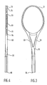
- FIG. 3 to 6 One form of possible moulded frame is shown in Figures 3 to 6. It has a head loop 21 for stringing and arms 22 joining the head to a shaft 20. Head loop 21 has stringing holes 23 in a recessed groove 24 running around its outer circumference.
- the frame is of a hollow, box-like construction having outer wall 21A, inner wall 21 B (i.e. with respect to the head loop) and sidewalls 21 C and 21 D.
- Hollow pillars 25 define the stringing holes 23 and provide support between outer wall 21 A and inner wall 21 B. Pillars 25 and holes 23 correspond to the positions of pins 16 of the core 10 of Figure 1. Larger diameter stringing holes 23A correspond to the positions of locating pins 14 of the core 10 of Figure 1.
- the construction of Figure 5 is also shown with solid pillars 27 and 28, one on each side of larger hole 23A. These solid pillars are an optional feature to add reinforcement to the frame section near to the larger holes. They are formed by the use of corresponding holes (not shown) in core 10 without pins.
- the larger holes 23A are conveniently lined with grommets such as that shown at 26.
- the annealed hollow frame made as described above may then be foam-filled as described below with reference to Figures 10 to 13.
- FIGS 8 and 9 Views of a foam-filled frame with integrally-formed foam handle are shown in Figures 8 and 9.
- the majority of the internal reinforcements such as 25, 27 and 28 of Figure 5 are not shown and only three reinforcements with their associated stringing holes 23 are shown.
- Racket frame 30 is in the form of a hollow injection moulded shell having, as before, a head loop 21 and arms 22 joining the head to a shaft 20.
- Head loop 21 has stringing holes 23 through internal reinforcements 25.
- the handle end of shaft 20 has holes 31 drilled or moulded in it.
- Head 21, arms 22 and a head-end portion of shaft 20 are filled with a relatively light polyurethane foam 32 which surrounds the internal reinforcements.
- the remainder of shaft 20 is filled with a relatively denser polyurethane foam 33.
- Foam 33 extends through holes 31 to form an integral handle 34. Foams 32 and 33 meet at boundary line 35 in shaft 20.
- FIGS. 10 to 13 illustrate one way of achieving the foam filling with integral handle and are described with reference to the following example.
- a hollow frame 36 was made by injection moulding from nylon 6.6 reinforced with 30% by weight of carbon fibres using the fusible core technique described above.
- the frame was found to weigh 252.
- Polyurethane precursors which produced a rigid foam of free rise density of 0.035 g/cm 3 were mixed together and 25 g of the mixture 37 were poured down the shaft 38 of the frame and into the hollow head region 39 (Figure 10).
- the volume into which the foam was allowed to expand was restricted by introducing a barrier in the form of a removable plug 40 in the desired position in the hollow shaft of the frame ( Figure 11). After about 10 minutes the plug was removed and the foam 41 found to be set.
- the handle end 38A of the shaft 38 was then introduced into a mould 42 which was arranged around the shaft in such a way as to define a cavity 43 having the shape of the required handle ( Figure 12).
- Polyurethane precursors which produce a rigid foam of free rise density 0.21 g/cm 3 were mixed together and 60 g of the mixture 44 poured down the shaft of the frame.
- This mixture foamed and the lid 47 of the mould was closed so that the foam 45 expanded through the holes 46 moulded in the handle end of the shaft of the frame and so filled the void remaining inside the shaft, i.e. up to the position of the foam 41 of lower density already in-situ, and also filled the cavity 43 defined by the mould surface ( Figure 13), thereby forming an integral foam handle.
- the frame was then painted and decorated and the handle completed by wrapping with a leather grip as in accepted practice.
- the frame was then strung with natural gut at a tension of 58 Ibs (26.31 kg).
- the strung frame in finished form was found to weigh 380 g and was found to balance at a position 327 mm from the extreme handle end.
- a metered dispenser may of course be used to supply the foam precursors to the hollow racket frames.
- the weight and balance of frames can be significantly changed. It has been found that the weight and balance of frames can be varied between limits acceptable to players, e.g.
Abstract
Description
- This invention relates to rackets for use in games, for example, tennis, squash and badminton, and is particularly concerned with the construction of the frames of these rackets.
- A recent development in the manufacture of racket frames is described in our BE-A-874,678, which describe a games racket frame comprising a head and a shaft, at least the head being a hollow injection moulding of thermoplastics material reinforced with short filament reinforcing material, as defined below, and in which the wall of the moulding which lies at the outer circumference of the head is joined to the wall which lies at the inner circumference of the head by an internal support means and the stringing holes in the head pass through the support means, the walls and support means of the moulding being integrally-formed. There is also described a method of making a frame for such a games racket, in which at least the head is formed by injecting a thermoplastics material around a fusible core, the core having a melting point below the injection temperature and being shaped to provide internal support means between that wall of the moulding that is to lie at the outer circumference of the head and that wall of the moulding that is to lie at the inner circumference of the head, allowing the moulding to set and then raising the temperature to an amount sufficient to melt the core but insufficient to melt or deform the moulding.
- By "short filament reinforcing material" here is meant short discrete lengths of fibre reinforcing material which are randomly dispersed in the thermoplastics matrix, i.e. in contrast to continuous filament reinforcements which are usually in the form of woven fabric or braid or aligned undirectionally in what is commonly referred to as a 'warp sheet' or 'warp strip'.
- The present invention is directed to a development of the racket frame described in the aforesaid application in which the formed, hollow moulded racket frame is given a filling of two different foam materials and an integrally- foamed handle.
- Rackets having a frame comprising a hollow plastics material shell filled with a foam core are well known, the foam core providing advantages such as good damping properties. Such rackets have either been proposed by fabricating a resin-impregnated fibre reinforcement around a pre-formed foam core or around a foam core precursor and setting the resin while, where appropriate, foaming the core or by making the hollow reinforced shell and then putting a foam precursor inside the shell and allowing it to foam. See for example GB-A-1,469,039 and GB-A-1,527,488 and our BE-A-874 678.
- We have now found that a combination of an injection moulding technique to provide the hollow shell of the frame followed by two foam-forming operations to fill the hollow frame, the latter foam-forming operation also being used to integrally-form a handle for the frame can provide a very good racket frame by a very efficient manufacturing process.
- Accordingly the present invention provides a games racket frame in the form of a hollow injection moulding of reinforced thermoplastics material, in which the frame comprises a head and a shaft, the wall of the moulding which lies at the outer circumference of the head is joined to the wall which lies at the inner circumference of the head by an internal support means and the stringing holes in the head pass through the support means, and the walls and support means of the moulding are integrally-formed, in which the hollow head of the frame has a filling of polyurethane foam of density from 0.10 to 0.25 wcm3 and the hollow shaft has a filling of rigid polyurethane foam of density from 0.30 to 0.50 g/cm3, the rigid polyurethane foam of the filling being integrally-formed with a rigid foam handle portion encasing the handle end of the shaft, and in which the two foam fillings meet at, or on the head side, of the handle.
- The invention also provides a games racket incorporating a frame according to the immediately preceding paragraph.
- The head fiiling may be of flexible or rigid polyurethane foam (the latter being preferred) and may extend, if desired, partway along the shaft up to a limit of the commencement of the handle portion of the shaft.
- The invention provides a convenient and advantageous way of obtaining racket frames having particular weight and balance properties. Thus it will be appreciated that the use of two foam fillings of different densities enables racket frames to be fabricated having a relatively wide range of balance characteristics at any given weight. At the same time the integral formation of the foam handles is a very convenient and economical method of providing a frame ready for the normal finishing operations, e.g. polishing, marking and the like, and stringing. The handle may be covered by any suitable means, e.g. a leather or towelling strip which can be adhered and/or pinned to the handle portion.
- It may be found convenient to use the same polyurethane foam formulation for the head filling and for the shaft filling. The required difference in final foam density can then be readily achieved by an appropriate calculation based on the weight of foam precursors used and the volume to be filled.
- Preferred polyurethane foams to be used in the invention are obtained from the reaction of a diisocyanate, e.g. methylene diisocyanate or tolylene diisocyanate, with a polyol, e.g. propylene glycol. The desired densities of the final foam fillings may be achieved, for example, by using quantities of precursors that would give a lighter than desired density if allowed to rise freely rather than being constrained within the volume of the hollow moulded frame. Thus, for example, the foam used for the head filling may have a free-rise density of 0.03 to 0.04 g/cm3 and the foam used for the shaft filling may have a free-rise density of 0.20 to 0.22 g/cm3. By accurate metering of the precursors and by constraining the foam, as it is generated, within certain volumetric limits it is possible to achieve substantially uniform foam quality without significant voids.
- The foam fillings can readily be made in-situ inside the hollow moulded frame as follows. The requisite amount of the light foam precursors are dispensed into the frame through the open end of the shaft. The frame may conveniently be held vertically with the head lowermost. A plunger is then inserted along the shaft as far as the calculated position necessary to give the desired foam density based on the volume and weight consideration referred to above. After the chemical reaction has proceeded and the foam has filled the head of the frame as far as the plunger and has sufficiently set, the handle end of the racket is then inserted in a mould having the configuration and dimensions of the desired handle. The requisite amount of the denser foam precursors are dispensed in the mould and foam to fill the shaft up to the point where the lighter foam ends and also to form the required handle portion the handle portion of the shaft is preferably provided with moulded-in holes to ensure full and free foaming of the precursors so that the inside of the shaft and the outside portion corresponding to the mould cavity are completely and integrally foamed.
- The hollow moulded frame used in this invention preferably has the preferred features of the frame disclosed in our BE-A-874 678. Thus the internal support means is preferably a row of centrally-disposed hollow pillars, the row extending arond the head portion of the frame. The axis of each pillar preferably lies in the plane of the strings of the racket and preferably is normal to the tangent to the circumference of the head at that point.
- However, if desired the axes of the pillars could lie at angles other than normal to that tangent and could for example, be aligned with the direction of the strings. The pillars are hollow so that each can provide a hole running from the outer circumference to the inner circumference of the head of the frame. The holes through the pillars thus conveniently provide the stringing holes for the frame. (With this construction, the presence of the pillars surrounding the holes means that the hollow frame can be foam-filled without the foam escaping through the stringing holes).
- In an alternative embodiment, each pillar may be in the form of an abutment from one or other of the sidewalls of the moulding, and preferably alternate pillars project from opposite walls. By sidewalls is meant those portions of the frame wall that constitute one or other of the two visible faces of the racket when it is viewed from the front or rear at right angles to the plane of the strings.
- The transverse sectional shape of the frame may be any desired shape, for example circular, oval or rectangular. The latter is preferred as its box-like section can give very high stiffness and strength to weight ratios. It is found advantageous to form in the outer circumference of the head a longitudinally extending groove or channel to recess the strings of the racket and safeguard them from abrasion. The transverse sectional shapes referred to immediately above, therefore, include those shapes when such a groove or channel is incorporated.
- Suitable thermoplastic materials from which the frame may be moulded include polyamides, polycarbonate, acrylonitrile-butadiene-styrene (ABS), acetal resins and poly(phenylene oxide) (PPO). (So-called 'modified' grades of PPO are now commercially available that are especially designed for injection-moulding applications).
- The plastics material used is preferably reinforced with glass fibres or carbon fibres. Carbon fibres are the preferred reinforcing means and injection mixtures containing from 10% to 40% by weight of carbon fibre are especially preferred. Mixtures of glass and carbon fibres may also be used.
- The wall thickness of the hollow frame of the invention need not be the same throughout and in fact the ability to vary the thickness may be a useful advantage. Zones of greater or lesser thickness may be utilised in order to optimise the required strength/weight and balance characteristics. For example, the wall thickness may be increased in the shoulder areas of the frame where considerable stress arises in use or similarly the thickness may be increased at the top of the head loop to improve impact- resistance.
- However, a better way of varying these characteristics around the frame is to vary the section of the frame rather than the wall thickness, particularly as there will be advantages in the moulding process and in the later annealing stages if the moulding has a substantially uniform wall thickness.
- The actual dimensions of the hollow section used will depend of course on the type of racket, e.g. whether for tennis, squash or badminton, and similarly the wall thickness will be governed by strength and weight requirements for the particular game. The average skilled man of the art will readily be able to decide suitable dimensions for his particular requirements. As an example only a useful wall thickness may be 2 mm.
- The invention is further described with reference to the accompanying drawings in which:-
- Figure 1 is a vertical section through a portion of an injection mould containing a metal core for a racket frame,
- Figure 2 is a section along line 11-11 of Figure 1,
- Figure 3 is an elevation of a moulded racket frame,
- Figure 4 is a side view of the frame of Figure 3,
- Figure 5 is a vertical section through a portion of the frame of Figure 3,
- Figure 6 is a section along line VI-VI of Figure 5,
- Figure 7 is a sectional view with parts cut away along line VII-VII of Figure 5,
- Figure 8 is a section in the stringing plane of a racket of the invention but with internal reinforcements not shown for clarity,
- Figure 9 is a view of the handle end of the racket in the direction of arrow A of Figure 8, and
- Figures 10 to 13 are diagrammatic representations illustrating four steps in the foam-forming stage in the manufacture of a racket of the invention.
- Figures 1 to 7 illustrate the manufacture of the hollow shell of an injection-moulded racket frame which can then be foam-filled to form a frame of the invention.
- Figure 1 for convenience illustrates that portion only of a mould core and injection mould that corresponds to the crown or top portion of a racket frame.
- A
core 10 of fusible metal is made by die- casting. It has the desired loop shape of the racket head and may also, if desired, extend to include a portion corresponding to the shaft of the racket. It is formed with a series of holes 11 running through the head portion transverse to the loop, these corresponding to the desired positions of the stringing holes of the racket frame. - The
core 10 is positioned inside a suitably- dimensioned and shapedinjection mould 12 and is held in the required position in themoulding chamber 13 by retractable locating pins 14. Agap 15 is thereby left surrounding the core and between it and the walls of thechamber 13, the gap corresponding to the desired walls of the frame moulding. A pin passes through each hole in the core. The majority of thepins 16 are of diameter less than that of the holes in the core whereby the walls of the supporting pillars of the eventual frame can be formed. Every few centimetres along the core, say 15 cm, a' locatingpin 14 is used which is of larger diameter and which completely fills its hole in the core. These larger diameter pins are provided withshoulders 17 to abut the core around the hole. Theshoulders 17 are positioned to be on the opposite side of the core to the injection ports of the mould (not shown) and thereby firmly hold the core in position against the injection pressure. The injection ports are preferably on the inside of the head loop. These larger diameter pins 14 of course result in pillarless holes of larger diameter than those through the pillars. These larger holes in the product can be subsequently lined with grommets, e.g., of plastics material. The locating pins are preferably positioned adjacent the injection ports of the mould. (It may in fact be found unnecessary to have the locating pins all around the core. Four locating pins, one on each side in the shoulder area and in the crown area may be found to be sufficient). - Fibre-reinforced thermoplastics material (nylon 6,6 incorporating 30% by weight of carbon fibres, for example, which is obtainable from Liquid Nitrogen Processing Corp. of Pennsylvania, U.S.A. under their reference RC-1006) is then injected into the mould and allowed to set.
- The
pins - A number of mouldings with their cores are batch-annealed in, for example, a forced-air oven. The temperature of annealing is sufficient to melt the metal cores and the molten metal runs out of appropriately-positioned holes in the mouldings into suitably placed containers. For example suitable drain holes could conveniently be provided, where head and shaft portions are integrally-formed, by designing the mould to leave open the
end 19 of theshaft 20 remote from the head 21 (see Figures 3 and 4). The mouldings can then be annealed while hanging withend 19 lowermost. Thus the heating step to melt the core can very conveniently be combined with an annealing step which may be desirable to remove internal strains from the moulding. - One form of possible moulded frame is shown in Figures 3 to 6. It has a
head loop 21 for stringing andarms 22 joining the head to ashaft 20.Head loop 21 has stringingholes 23 in a recessedgroove 24 running around its outer circumference. - As will be seen from the sectional views of Figures 5, 6 and 7, the frame is of a hollow, box-like construction having
outer wall 21A,inner wall 21 B (i.e. with respect to the head loop) andsidewalls 21 C and 21D. Hollow pillars 25 define the stringing holes 23 and provide support betweenouter wall 21 A andinner wall 21B. Pillars 25 and holes 23 correspond to the positions ofpins 16 of thecore 10 of Figure 1. Largerdiameter stringing holes 23A correspond to the positions of locatingpins 14 of thecore 10 of Figure 1. The construction of Figure 5 is also shown withsolid pillars larger hole 23A. These solid pillars are an optional feature to add reinforcement to the frame section near to the larger holes. They are formed by the use of corresponding holes (not shown) incore 10 without pins. Thelarger holes 23A are conveniently lined with grommets such as that shown at 26. - The annealed hollow frame made as described above may then be foam-filled as described below with reference to Figures 10 to 13.
- Views of a foam-filled frame with integrally-formed foam handle are shown in Figures 8 and 9. For the sake of clarity the majority of the internal reinforcements such as 25, 27 and 28 of Figure 5 are not shown and only three reinforcements with their associated stringing holes 23 are shown.
-
Racket frame 30 is in the form of a hollow injection moulded shell having, as before, ahead loop 21 andarms 22 joining the head to ashaft 20.Head loop 21 has stringingholes 23 throughinternal reinforcements 25. The handle end ofshaft 20 hasholes 31 drilled or moulded in it. -
Head 21,arms 22 and a head-end portion ofshaft 20 are filled with a relativelylight polyurethane foam 32 which surrounds the internal reinforcements. The remainder ofshaft 20 is filled with a relativelydenser polyurethane foam 33.Foam 33 extends throughholes 31 to form anintegral handle 34.Foams boundary line 35 inshaft 20. - Figures 10 to 13 illustrate one way of achieving the foam filling with integral handle and are described with reference to the following example.
- A
hollow frame 36 was made by injection moulding from nylon 6.6 reinforced with 30% by weight of carbon fibres using the fusible core technique described above. The frame was found to weigh 252. Polyurethane precursors which produced a rigid foam of free rise density of 0.035 g/cm3 were mixed together and 25 g of themixture 37 were poured down theshaft 38 of the frame and into the hollow head region 39 (Figure 10). The volume into which the foam was allowed to expand was restricted by introducing a barrier in the form of aremovable plug 40 in the desired position in the hollow shaft of the frame (Figure 11). After about 10 minutes the plug was removed and thefoam 41 found to be set. Thehandle end 38A of theshaft 38 was then introduced into amould 42 which was arranged around the shaft in such a way as to define acavity 43 having the shape of the required handle (Figure 12). Polyurethane precursors which produce a rigid foam of free rise density 0.21 g/cm3 were mixed together and 60 g of themixture 44 poured down the shaft of the frame. This mixture foamed and thelid 47 of the mould was closed so that thefoam 45 expanded through theholes 46 moulded in the handle end of the shaft of the frame and so filled the void remaining inside the shaft, i.e. up to the position of thefoam 41 of lower density already in-situ, and also filled thecavity 43 defined by the mould surface (Figure 13), thereby forming an integral foam handle. - After 10 minutes the frame was removed from the handle mould and excess material trimmed away.
- The frame was then painted and decorated and the handle completed by wrapping with a leather grip as in accepted practice. The frame was then strung with natural gut at a tension of 58 Ibs (26.31 kg).
- The strung frame in finished form was found to weigh 380 g and was found to balance at a position 327 mm from the extreme handle end.
- A metered dispenser may of course be used to supply the foam precursors to the hollow racket frames.
- By varying the weight of the polyurethane precursors used for filling both the head and the lower shaft/handle area the weight and balance of frames can be significantly changed. It has been found that the weight and balance of frames can be varied between limits acceptable to players, e.g.

Claims (9)
Priority Applications (1)
| Application Number | Priority Date | Filing Date | Title |
|---|---|---|---|
| AT80104719T ATE2720T1 (en) | 1979-08-24 | 1980-08-11 | RACKET FRAME. |
Applications Claiming Priority (2)
| Application Number | Priority Date | Filing Date | Title |
|---|---|---|---|
| GB7929589 | 1979-08-24 | ||
| GB7929589 | 1979-08-24 |
Publications (2)
| Publication Number | Publication Date |
|---|---|
| EP0025126A1 EP0025126A1 (en) | 1981-03-18 |
| EP0025126B1 true EP0025126B1 (en) | 1983-03-09 |
Family
ID=10507421
Family Applications (1)
| Application Number | Title | Priority Date | Filing Date |
|---|---|---|---|
| EP80104719A Expired EP0025126B1 (en) | 1979-08-24 | 1980-08-11 | Games racket frame |
Country Status (11)
| Country | Link |
|---|---|
| US (1) | US4340226A (en) |
| EP (1) | EP0025126B1 (en) |
| JP (1) | JPS596666B2 (en) |
| KR (1) | KR830001507B1 (en) |
| AT (1) | ATE2720T1 (en) |
| AU (1) | AU530705B2 (en) |
| CA (1) | CA1133531A (en) |
| DE (1) | DE3062290D1 (en) |
| ES (1) | ES8106087A1 (en) |
| GB (1) | GB2056864B (en) |
| ZA (1) | ZA805014B (en) |
Families Citing this family (29)
| Publication number | Priority date | Publication date | Assignee | Title |
|---|---|---|---|---|
| FR2528318A1 (en) * | 1982-06-14 | 1983-12-16 | Cousin Freres Sa | Tennis racquet frames of hollow thermoplastic extrudate - subsequently shaped and filled, pref. of fibre reinforced polyamide plugged with expanded polyurethane |
| DE3373783D1 (en) * | 1982-06-14 | 1987-10-29 | Cousin Freres Sa | Tennis racket frame and method of manufacturing it |
| GB8327851D0 (en) * | 1983-10-18 | 1983-11-16 | Mott J C | Racquets |
| US4614626A (en) * | 1984-04-27 | 1986-09-30 | Frerking James R | Method for fabricating a tennis racquet frame |
| JPS6182769A (en) * | 1984-09-28 | 1986-04-26 | 株式会社ブリヂストン | Tennis racket made of synthetic resin |
| FR2592804B1 (en) * | 1986-01-13 | 1989-04-07 | Rossignol Sa | TENNIS RACKET IN LAMINATE MATERIAL |
| US4989870A (en) * | 1988-05-16 | 1991-02-05 | Spalding & Evenflo Companies, Inc. | Tennis racket |
| US4983242A (en) * | 1988-11-02 | 1991-01-08 | Roland Reed | Tennis racquet having a sandwich construction, vibration-dampening frame |
| FR2656537B1 (en) * | 1990-01-02 | 1993-05-28 | Jeanrot Patrick | RACKET COMPRISING AN INJECTED HANDLE AND ITS MANUFACTURING METHOD. |
| US5236198A (en) * | 1990-05-02 | 1993-08-17 | Dunlop Limited | Games racket frame |
| GB9009831D0 (en) * | 1990-05-02 | 1990-06-27 | Dunlop Ltd | Games racket frame |
| GB2246111B (en) * | 1990-07-13 | 1994-05-04 | Samsung Heavy Ind | Dipper stick for excavator of high strength polymeric composite materials and method for manufacturing such |
| US5524884A (en) * | 1991-07-18 | 1996-06-11 | Dunlop Limited | Striking implements |
| US5242162A (en) * | 1991-08-02 | 1993-09-07 | Arthur Hong | String holes of a sports racket frame |
| US5876134A (en) * | 1992-02-14 | 1999-03-02 | The Gillette Company | Foam grip |
| US5310516A (en) * | 1992-05-06 | 1994-05-10 | Walter Shen | Method of making a composite racket |
| CH686227A5 (en) * | 1992-10-15 | 1996-02-15 | Busch & Cie Composites | hockey stick. |
| US5423533A (en) * | 1994-03-28 | 1995-06-13 | Hsu; Henry Y. C. | Game racket of composite material |
| US5651740A (en) * | 1994-10-24 | 1997-07-29 | Munoz; John A. | Foamed core products and method |
| US5806919A (en) * | 1996-11-04 | 1998-09-15 | General Motors Corporation | Low density-high density insert reinforced structural joints |
| US5922255A (en) * | 1997-04-04 | 1999-07-13 | Highlander Sports, Llc | Method of manufacturing a racket frame and throat |
| US7955693B2 (en) * | 2001-04-20 | 2011-06-07 | Tolland Development Company, Llc | Foam composition roller brush with embedded mandrel |
| GB2391486B (en) * | 2002-08-09 | 2005-08-24 | Timothy William Keeley | Sports bat handle |
| US20050043123A1 (en) * | 2003-08-22 | 2005-02-24 | Harvey Charles M. | Lacrosse stick |
| CA2454725C (en) * | 2003-12-31 | 2008-08-05 | Chrislan Ceramics And Glassware Decorating Inc. | Safety tap handle |
| US7077768B2 (en) * | 2004-05-27 | 2006-07-18 | Ef Composite Technologies, L.P. | Composite racquet with double tube head frame |
| US7736251B2 (en) * | 2004-07-26 | 2010-06-15 | Quikstick Lacrosse, Llc | Lacrosse stick |
| US20070191154A1 (en) * | 2006-02-10 | 2007-08-16 | Genereux Dana A | Racquet sport apparatus & method |
| WO2023227819A1 (en) * | 2022-05-27 | 2023-11-30 | Padel Series, S.L.U. | Method for producing a padel racket and padel racket thus obtained |
Family Cites Families (14)
| Publication number | Priority date | Publication date | Assignee | Title |
|---|---|---|---|---|
| US3265401A (en) * | 1964-01-29 | 1966-08-09 | Spier I Martin | Reinforcement for a pole |
| DE1578590A1 (en) * | 1967-11-10 | 1971-08-19 | Friedrich Hutter | Construction for tennis racket frame |
| US3801098A (en) * | 1971-09-15 | 1974-04-02 | Nl Industries Inc | Metal baseball bat |
| US3810620A (en) * | 1971-12-28 | 1974-05-14 | C Decker | Sports racket |
| GB1469039A (en) * | 1974-02-13 | 1977-03-30 | Fansteel Inc | Elongate composite aritcles |
| US4025377A (en) * | 1974-03-14 | 1977-05-24 | Yukio Tanikawa | Method of producing a baseball bat |
| US3986716A (en) * | 1974-09-23 | 1976-10-19 | Arundale Manufacturers, Inc. | Composite racquet structure |
| US3990701A (en) * | 1974-11-26 | 1976-11-09 | Sung Baik Kim | Tennis racket |
| US4119313A (en) * | 1975-07-12 | 1978-10-10 | Dunlop Limited | Games racquets |
| US4099718A (en) * | 1976-05-17 | 1978-07-11 | Marcraft Recreation Inc. | Racquet frame construction |
| CH614380A5 (en) * | 1976-07-28 | 1979-11-30 | Rossignol Sa | |
| JPS5344235A (en) * | 1976-10-04 | 1978-04-20 | Nippon Gakki Seizo Kk | Racket frame and method of manufacturing the same |
| JPS5412930A (en) * | 1977-06-30 | 1979-01-31 | Hitachi Chem Co Ltd | Racket frame |
| US4297308A (en) * | 1978-03-07 | 1981-10-27 | Dunlop Limited | Method of manufacturing games rackets |
-
1980
- 1980-08-11 DE DE8080104719T patent/DE3062290D1/en not_active Expired
- 1980-08-11 AT AT80104719T patent/ATE2720T1/en not_active IP Right Cessation
- 1980-08-11 EP EP80104719A patent/EP0025126B1/en not_active Expired
- 1980-08-12 US US06/177,394 patent/US4340226A/en not_active Expired - Lifetime
- 1980-08-15 ZA ZA00805014A patent/ZA805014B/en unknown
- 1980-08-19 GB GB8027038A patent/GB2056864B/en not_active Expired
- 1980-08-22 AU AU61674/80A patent/AU530705B2/en not_active Ceased
- 1980-08-22 CA CA358,869A patent/CA1133531A/en not_active Expired
- 1980-08-22 ES ES494441A patent/ES8106087A1/en not_active Expired
- 1980-08-23 KR KR1019800003338A patent/KR830001507B1/en active
- 1980-08-25 JP JP55116908A patent/JPS596666B2/en not_active Expired
Also Published As
| Publication number | Publication date |
|---|---|
| JPS5634362A (en) | 1981-04-06 |
| US4340226A (en) | 1982-07-20 |
| GB2056864A (en) | 1981-03-25 |
| JPS596666B2 (en) | 1984-02-14 |
| ATE2720T1 (en) | 1983-03-15 |
| ES494441A0 (en) | 1981-07-16 |
| ZA805014B (en) | 1981-09-30 |
| ES8106087A1 (en) | 1981-07-16 |
| CA1133531A (en) | 1982-10-12 |
| KR830003221A (en) | 1983-06-18 |
| AU6167480A (en) | 1981-03-05 |
| AU530705B2 (en) | 1983-07-28 |
| GB2056864B (en) | 1983-03-16 |
| DE3062290D1 (en) | 1983-04-14 |
| EP0025126A1 (en) | 1981-03-18 |
| KR830001507B1 (en) | 1983-08-08 |
Similar Documents
| Publication | Publication Date | Title |
|---|---|---|
| EP0025126B1 (en) | Games racket frame | |
| US4297308A (en) | Method of manufacturing games rackets | |
| US4874171A (en) | Golf club set | |
| US3958291A (en) | Outer shell construction for boot and method of forming same | |
| US5143669A (en) | Fiber-reinforced molded racquet frame | |
| US4614627A (en) | Method of injection molding a thermoplastic hollow or hollow foam filled one piece head of a golf club | |
| US3981504A (en) | Glass-carbon reinforced foamed resin tennis racket frame | |
| US5746955A (en) | Process for making a composite hockey stick shaft | |
| CN102612427A (en) | Fiber composite and process of manufacture | |
| US4891175A (en) | Games racket | |
| US5075056A (en) | Process for the production of a ball game racket frame | |
| EP0504230B1 (en) | Hockey stick | |
| US4842798A (en) | Method of moulding racquets with stringing holes | |
| US4747598A (en) | Racket frame having interiorly located stringing lugs | |
| US5651740A (en) | Foamed core products and method | |
| EP0401498A2 (en) | Hollow, elongate mouldings | |
| GB2227444A (en) | Injection moulding hollow articles | |
| JPS58212464A (en) | Racket and production thereof | |
| JP2872935B2 (en) | Method of manufacturing FRP bat | |
| Haines et al. | The design, development and manufacture of a new and unique tennis racket | |
| KR910000909B1 (en) | Process for the production of f.r.p. articles | |
| GB2029705A (en) | Racket | |
| IE980872A1 (en) | A moulded hurley | |
| IES81083B2 (en) | A moulded hurley | |
| JPH0417671B2 (en) |
Legal Events
| Date | Code | Title | Description |
|---|---|---|---|
| PUAI | Public reference made under article 153(3) epc to a published international application that has entered the european phase |
Free format text: ORIGINAL CODE: 0009012 |
|
| AK | Designated contracting states |
Designated state(s): AT BE DE FR GB IT NL SE |
|
| 17P | Request for examination filed |
Effective date: 19810306 |
|
| ITF | It: translation for a ep patent filed |
Owner name: GUZZI E RAVIZZA S.R.L. |
|
| GRAA | (expected) grant |
Free format text: ORIGINAL CODE: 0009210 |
|
| AK | Designated contracting states |
Designated state(s): AT BE DE FR GB IT NL SE |
|
| REF | Corresponds to: |
Ref document number: 2720 Country of ref document: AT Date of ref document: 19830315 Kind code of ref document: T |
|
| REF | Corresponds to: |
Ref document number: 3062290 Country of ref document: DE Date of ref document: 19830414 |
|
| ET | Fr: translation filed | ||
| PGFP | Annual fee paid to national office [announced via postgrant information from national office to epo] |
Ref country code: DE Payment date: 19840627 Year of fee payment: 5 |
|
| PGFP | Annual fee paid to national office [announced via postgrant information from national office to epo] |
Ref country code: SE Payment date: 19840630 Year of fee payment: 5 |
|
| PGFP | Annual fee paid to national office [announced via postgrant information from national office to epo] |
Ref country code: FR Payment date: 19840705 Year of fee payment: 5 |
|
| PGFP | Annual fee paid to national office [announced via postgrant information from national office to epo] |
Ref country code: BE Payment date: 19840930 Year of fee payment: 5 |
|
| PGFP | Annual fee paid to national office [announced via postgrant information from national office to epo] |
Ref country code: AT Payment date: 19860627 Year of fee payment: 7 |
|
| PGFP | Annual fee paid to national office [announced via postgrant information from national office to epo] |
Ref country code: NL Payment date: 19870831 Year of fee payment: 8 |
|
| PG25 | Lapsed in a contracting state [announced via postgrant information from national office to epo] |
Ref country code: GB Effective date: 19890811 Ref country code: AT Effective date: 19890811 |
|
| PG25 | Lapsed in a contracting state [announced via postgrant information from national office to epo] |
Ref country code: SE Effective date: 19890812 |
|
| PG25 | Lapsed in a contracting state [announced via postgrant information from national office to epo] |
Ref country code: BE Effective date: 19890831 |
|
| BERE | Be: lapsed |
Owner name: DUNLOP LTD Effective date: 19890831 |
|
| PG25 | Lapsed in a contracting state [announced via postgrant information from national office to epo] |
Ref country code: NL Effective date: 19900301 |
|
| GBPC | Gb: european patent ceased through non-payment of renewal fee | ||
| NLV4 | Nl: lapsed or anulled due to non-payment of the annual fee | ||
| PG25 | Lapsed in a contracting state [announced via postgrant information from national office to epo] |
Ref country code: FR Effective date: 19900427 |
|
| PG25 | Lapsed in a contracting state [announced via postgrant information from national office to epo] |
Ref country code: DE Effective date: 19900501 |
|
| REG | Reference to a national code |
Ref country code: FR Ref legal event code: ST |
|
| EUG | Se: european patent has lapsed |
Ref document number: 80104719.2 Effective date: 19900418 |
|
| PLBE | No opposition filed within time limit |
Free format text: ORIGINAL CODE: 0009261 |
|
| STAA | Information on the status of an ep patent application or granted ep patent |
Free format text: STATUS: NO OPPOSITION FILED WITHIN TIME LIMIT |