EP0025101A1 - Braking force regulator for hydraulic motorcycle brake system - Google Patents
Braking force regulator for hydraulic motorcycle brake system Download PDFInfo
- Publication number
- EP0025101A1 EP0025101A1 EP80104150A EP80104150A EP0025101A1 EP 0025101 A1 EP0025101 A1 EP 0025101A1 EP 80104150 A EP80104150 A EP 80104150A EP 80104150 A EP80104150 A EP 80104150A EP 0025101 A1 EP0025101 A1 EP 0025101A1
- Authority
- EP
- European Patent Office
- Prior art keywords
- pressure
- brake
- valve
- master cylinder
- piston
- Prior art date
- Legal status (The legal status is an assumption and is not a legal conclusion. Google has not performed a legal analysis and makes no representation as to the accuracy of the status listed.)
- Granted
Links
- 238000007789 sealing Methods 0.000 claims abstract description 8
- 230000001603 reducing effect Effects 0.000 claims description 6
- 238000006073 displacement reaction Methods 0.000 description 14
- 238000000034 method Methods 0.000 description 9
- 230000000694 effects Effects 0.000 description 5
- 238000010586 diagram Methods 0.000 description 3
- 238000004519 manufacturing process Methods 0.000 description 3
- 238000010276 construction Methods 0.000 description 2
- 239000012530 fluid Substances 0.000 description 1
- 229910052757 nitrogen Inorganic materials 0.000 description 1
- 229910052698 phosphorus Inorganic materials 0.000 description 1
- 238000001228 spectrum Methods 0.000 description 1
Images


Classifications
-
- B—PERFORMING OPERATIONS; TRANSPORTING
- B60—VEHICLES IN GENERAL
- B60T—VEHICLE BRAKE CONTROL SYSTEMS OR PARTS THEREOF; BRAKE CONTROL SYSTEMS OR PARTS THEREOF, IN GENERAL; ARRANGEMENT OF BRAKING ELEMENTS ON VEHICLES IN GENERAL; PORTABLE DEVICES FOR PREVENTING UNWANTED MOVEMENT OF VEHICLES; VEHICLE MODIFICATIONS TO FACILITATE COOLING OF BRAKES
- B60T8/00—Arrangements for adjusting wheel-braking force to meet varying vehicular or ground-surface conditions, e.g. limiting or varying distribution of braking force
- B60T8/26—Arrangements for adjusting wheel-braking force to meet varying vehicular or ground-surface conditions, e.g. limiting or varying distribution of braking force characterised by producing differential braking between front and rear wheels
- B60T8/261—Arrangements for adjusting wheel-braking force to meet varying vehicular or ground-surface conditions, e.g. limiting or varying distribution of braking force characterised by producing differential braking between front and rear wheels specially adapted for use in motorcycles
-
- B—PERFORMING OPERATIONS; TRANSPORTING
- B62—LAND VEHICLES FOR TRAVELLING OTHERWISE THAN ON RAILS
- B62L—BRAKES SPECIALLY ADAPTED FOR CYCLES
- B62L3/00—Brake-actuating mechanisms; Arrangements thereof
- B62L3/08—Mechanisms specially adapted for braking more than one wheel
Definitions
- the invention relates to a brake force regulator for a hydraulic motorcycle brake system in which a rear master brake and a first front brake and a second master brake can be pressurized by a master cylinder and in which the pressurization of the rear brake depending on the pressure generated by the master cylinder can be reduced and the brake force regulator has a stepped piston which can be displaced against the force of a return spring, the larger effective area of which delimits a pressure inlet chamber and can be pressurized by the foot master cylinder and the smaller effective area delimits a pressure outlet chamber and can be pressurized by the pressure in the rear wheel brake, and with a first valve through which one Pressure medium connection between the pressure inlet chamber and the pressure outlet chamber is closable and a second valve which, depending on the pressure generated in the master cylinder, a pressure medium connection z wipe the first front brake and the foot master cylinder interrupts.
- a braking force regulator is already known from De-OS 27 42 204, which is constructed in such a way that when the foot brake is actuated, the rear wheel is braked relative to the front wheel. Subsequent actuation of the handbrake applies a second front wheel brake and at the same time the brake pressure of the rear wheel brake is reduced.
- a sufficient effect of the rear wheel brake can, however, only be achieved if the pressure generated by the hand master cylinder is low when the foot brake is added, otherwise there is still a risk that the front wheel will lock up. It is assumed that the driver normally first actuates the foot master cylinder and, if necessary, later also actuates the handbrake, but the reverse sequence of operations is possible and should occur in particular if the driver initially considers only a slight braking using the handbrake to be necessary and later, for some reason, a greater delay and therefore the use of the foot brake becomes necessary. This sequence of operations is also conceivable for panic braking.
- German patent application P 28 54 970.4 has already created a braking force regulator in which, regardless of the sequence of actuation of the two master cylinders and regardless of the prevailing one Pressure of one brake circuit at the start of actuation of the other brake circuit a large vehicle deceleration is achieved.
- this regulator is complex in terms of its construction and therefore expensive to manufacture.
- an A chsenversatz of each piston is not ruled out, which may lead to the inoperability of the controller.
- the main advantages of the brake force regulator according to the invention can be seen in the fact that even with an actuation sequence in which the hand master cylinder is operated first and later the foot master cylinder, a further approximation to the greatest possible vehicle deceleration is possible, and that the product is considerably cheaper due to the fact that it is easy to manufacture and easily assembled parts is achieved.
- An advantageous development of the subject matter of the invention is that the valve closing member is attached to a piston which interacts with a control piston acted upon by the pressure of the manual master cylinder. This arrangement of the mechanical actuation of the second valve does not require any additional pressure medium lines inside or outside of the regulator housing.
- the second valve is preferably designed as a pressure reducing valve, the pressure reducing effect of which can be canceled when a determinable pressure level is reached.
- a particularly simple embodiment of the pressure reducing valve consists in the fact that it comprises a conical end of the valve closing member and a second stepped piston with a central bore, the end of which is formed as a valve seat, the end of which is adjacent to the valve closing member.
- the second stepped piston has an axially parallel second bore of smaller diameter and a flap valve is arranged in the bore.
- a throttle is connected in parallel with the second valve.
- the valves are arranged in such a way that the second valve is open when the first valve is closed.
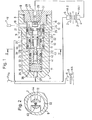
- a motorcycle brake system which consists of a hand master cylinder H Hz , a foot master cylinder F Hz 'of a first and a second front brake VA 1, VA 2 and a rear wheel brake HA and a brake force regulator 1.
- the front brake VA 1, VA 2 and the rear brake HA are disc brakes, each with a brake disc 2, 2 ', 3 and a brake caliper 4, 4' 5.
- the brake force regulator 1 consists of a housing 6 with a stepped blind bore 7, 7 ', which has a thread 8 at its open end and is closed by means of a screw 9.
- a first sleeve 10 is then arranged in the bore section 7 at the bore section 7 ′ and sealed against the housing 6 by means of a seal 11.
- a first step piston 12 is located with its larger piston step in the bore 7 on the side of the sleeve 10 facing the screw 9 and its smaller piston step penetrates the sleeve 10.
- the step piston 12 is by means of a seal 13 against the housing 6 and by means of a Seal 14 sealed against the sleeve 10.
- the stepped piston 12 delimits a pressure inlet chamber 15 with its larger piston step and a pressure outlet chamber 16 with an annular surface.
- the chambers 15 and 16 are connected to one another by an axial pressure medium passage 17 and a radial bore 18.
- a pressure medium connection 19 opening into the pressure inlet chamber 15 and a pressure medium connection 20 opening into the pressure outlet chamber 16, the pressure medium connection 19 being connected to the foot master cylinder F Hz and the pressure medium connection 20 being connected to the brake caliper 5 of the rear wheel brake HA.
- a piston 22 provided with a valve closing member 21 is guided and sealed against the stepped piston 12 by a seal 23.
- the valve closing member 21 has a sealing ring 24 with a radial sealing surface which lies opposite a radial surface of the stepped piston 12 serving as a valve seat 25.
- the piston 22 is biased in the valve opening direction by a spring 26 with a low spring force, the valve closing member 21 abutting the screw 9.
- a pressure medium connection 27 opening into the pressure inlet chamber 15 is provided, which is connected to the brake caliper 4 'of the first front brake VA 1.
- the end of the pressure medium connection 27 facing the valve closing member 21 is designed as a valve seat 28, which lies opposite a conical end 29 of the valve closing member 21.
- a cross member 32 is clamped between the sleeve 10 and the step of the bore 7, 7 'and penetrates the slotted end of the smaller piston step of the step piston 12.
- the stepped piston 12 is supported on the end face of a pressure piston 33, which is sealed against the housing 6 by means of a seal 34 and delimits a pressure chamber 35 with the other end face.
- a return spring 36 is arranged in the pressure chamber 35 and loads the pressure piston 33 in the direction of the stepped piston 12 and against the screw 9.
- the pressure chamber 35 is provided with a pressure medium connection 37 which is connected to the master cylinder H Hz .
- a cavity 38 is formed between the pressure piston 32 and the sleeve 10 and is connected to the atmosphere by an opening 39 in the housing 6.
- the pressure piston 33 has a coaxial bore 40 in which a control piston 41 acted upon by the pressure in the pressure chamber 35 is arranged and sealed against the wall of the bore by means of a seal 42.
- a control piston 41 acted upon by the pressure in the pressure chamber 35 is arranged and sealed against the wall of the bore by means of a seal 42.
- Fig. 2 is the section along the line II-II in Fi g. 1 shown.
- the cross member 32 In the housing 6 with the bore 7 is the cross member 32 arranged, which penetrates the slotted end of the stepped piston 12.
- the tapered end 43 of the control piston 41 is located in the opening 44 of the cross member 32.
- the braking force regulator shown in FIG. 3 corresponds in substantial parts to that in FIG. 1, so that, in order to avoid repetitions, only the differences from the arrangement described above are dealt with.
- the reference numerals from FIG. 1 have been adopted for identical parts.
- the housing 6 is extended in the part between the inlet chamber 15 and the screw 9.
- a sleeve 45 is inserted, which lies on its side facing the screw 9 against a ring 46 fixed to the housing and on its other side serves as a stop for the stepped piston 12.
- the sleeve 45 is sealed against the housing 6 by means of a seal 47.
- a second step piston 48 is guided with its smaller step in the sleeve 45 and with its larger step in the bore 7 and sealed by means of seals 49 and 50.
- the end face of the smaller piston stage delimits the inlet chamber 15 and the end face of the larger piston stage delimits a second pressure outlet chamber 51.
- a coaxial bore 54 in the second stepped piston 48 connects the chambers 15 and 51.
- the end of the bore 54 facing the first stepped piston 12 serves as a valve seat 28 of the tapered end 29 of the closing member 21.
- a flap valve 56 is provided in the second stepped piston 48 in the second stepped piston 48 .
- the second step piston 48 is provided with a stop 57 which limits the displacement of the step piston 48 in the direction of the inlet chamber 15.
- a conical surface 24 is provided on the valve closing member 21.
- FIGS. 4 and 5 each show diagrams with brake pressure distribution curves, the brake pressure of the rear axle being plotted as a function of the total brake pressure of the front axle.
- Curve 1 corresponds to the ideal brake pressure distribution for a specific load condition of the motorcycle.
- Z indicates the delay.
- the course of the brake pressure distribution curves is explained in the functional description.
- the mode of operation of the brake force regulator shown in FIGS. 1 and 3 depends on the actuation order of the master cylinder and on the moment in which the respective master cylinder is actuated. These possible variations result in a large spectrum of brake pressure distribution characteristics, of which only two examples are described.
- the brake pressure distribution curves correspond in principle. the B Rems described power controllers, but they are not exactly in view of the indicated area ratios. This is not necessary because the area ratios are freely selectable.
- a pressure is built up in the pressure chamber 35 by the hand master cylinder H Hz , which acts on the pressure piston 33 and displaces it in the direction of the stepped piston 12. Since the stepped piston 12 interacts with the pressure piston 33, it too is displaced in the same way. Now there is only an increase in the brake pressure in the front brake VA 2 acted upon by the master cylinder H Hz. However, the prerequisite for this is that the master cylinder F is no longer actuated, but is only held. This pressure increase in the pressure chamber 35 causes the stepped piston 12 to be displaced while the pressure medium passage 17 is closed, thereby reducing the volume of the pressure inlet chamber 15 and increasing the volume of the pressure outlet chamber 16. There is now an additional pressure increase in the front wheel brake VA 1 due to the reduction in volume of the chamber 15 and a reduction in pressure in the rear wheel brake HA due to the increase in volume in the chamber 16. This gives the characteristic curve from F to G,
- H is the point at which the driver maintains the position of the hand master cylinder and additionally actuates the foot master cylinder F Hz .
- a pressure is built up in the pressure inlet chamber 15 by the foot master cylinder, which pressure continues through the opened pressure medium passage 17 into the pressure outlet chamber 16 and further to the rear wheel brake HA. Due to the pressurization of the piston 41 by the pressure prevailing in the pressure chamber 35, the conical end 29 is held on its valve seat 28. The pressure prevailing in the pressure inlet chamber 15 is therefore reduced through the transverse bore 31 and the throttle bore 30 to the front brake VA 1. A course of the characteristic curve from point H to point K is thereby achieved.
- valve closing member 21 lies with its conical surface 24 on the valve seat 25 and closes the pressure medium passage 17th
- the final opening of the valve 28, 29 has the result that there is pressure equalization between the pressure inlet chamber 15 and the second pressure outlet chamber 51.
- This pressure compensation is shown in the characteristic curve by the distance from B to C.
- S is the point at which the pressure in the inlet chamber 15 is so great that the force acting on the piston 22 overcomes the force of the spring 26 and the pressure force acting on the control piston 41 and the piston 22 moves against its bias .
- This opens the valve 28, 29 while simultaneously closing the valve 21, 25.
- the pressure at the front brake VA 1 increases to a value corresponding to the reduction ratio.
- the pressure in the rear wheel brake With a further increase in pressure in the pressure inlet chamber 15, the pressure in the rear wheel brake remains constant until the force effect on the pressure piston 33 generated by the hand master cylinder H Hz is balanced. At the same time, a pressure is built up in the front brake VA 1, which pressure is reduced in accordance with the reduction ratio of the stepped piston 48 compared to the pressure generated in the foot master cylinder. The point at which the force effect on the pressure piston 33 is equalized is designated T in the characteristic curve.
- a further pressure increase by the foot master cylinder F Hz results in a pressure increase in the rear wheel brake. This pressure increase takes place until the piston 22 reaches the cross member 33 and is prevented from further displacement by the latter. Point M of the characteristic curve is thus reached.
Landscapes
- Engineering & Computer Science (AREA)
- Mechanical Engineering (AREA)
- Transportation (AREA)
- Hydraulic Control Valves For Brake Systems (AREA)
- Regulating Braking Force (AREA)
Abstract
Description
Die Erfindung bezieht sich auf einen Bremskraftregler für ein hydraulisches Motorrad-Bremssystem, bei dem von einem Fußhauptzylinder eine Hinterradbremse und eine erste Vorderradbremse und mittels eines Handhauptzylinders eine zweite Vorderradbremse druckbeaufschlagbar sind und bei dem die Druckbeaufschlagung der Hinterradbremse in Abhängigkeit vom mit dem Handhauptzylinder erzeugten Druck minderbar ist und der Bremskraftregler einen gegen die Kraft einer Rückstellfeder verschiebbaren Stufenkolben hat, dessen größere Wirkfläche eine Druckeinlaßkammer begrenzt und vom Fußhauptzylinder druckbeaufschlagbar ist und dessen kleinere Wirkfläche eine Druckauslaßkammer begrenzt und vom Druck in der Hinterradbremse druckbeaufschlagbar ist, und mit einem ersten Ventil, durch das eine Druckmittelverbindung zwischen der Druckeinlaßkammer und der Druckauslaßkammer verschließbar ist und einem zweiten Ventil, welches in Abhängigkeit vom im Handhauptzylinder erzeugten Druck eine Druckmittelverbindung zwischen der ersten Vorderradbremse und dem Fußhauptzylinder unterbricht.The invention relates to a brake force regulator for a hydraulic motorcycle brake system in which a rear master brake and a first front brake and a second master brake can be pressurized by a master cylinder and in which the pressurization of the rear brake depending on the pressure generated by the master cylinder can be reduced and the brake force regulator has a stepped piston which can be displaced against the force of a return spring, the larger effective area of which delimits a pressure inlet chamber and can be pressurized by the foot master cylinder and the smaller effective area delimits a pressure outlet chamber and can be pressurized by the pressure in the rear wheel brake, and with a first valve through which one Pressure medium connection between the pressure inlet chamber and the pressure outlet chamber is closable and a second valve which, depending on the pressure generated in the master cylinder, a pressure medium connection z wipe the first front brake and the foot master cylinder interrupts.
Aus der De-OS 27 42 204 ist bereits ein Bremskraftregler bekannt, der so konstruiert ist, daß bei Betätigung der Fußbremse das Hinterrad gegenüber dem Vorderrad überbremst wird. Durch anschließende Betätigung der Handbremse wird eine zweite Vorderradbremse beaufschlagt und gleichzeitig der Bremsdruck der Hinterradbremse abgesenkt.A braking force regulator is already known from De-OS 27 42 204, which is constructed in such a way that when the foot brake is actuated, the rear wheel is braked relative to the front wheel. Subsequent actuation of the handbrake applies a second front wheel brake and at the same time the brake pressure of the rear wheel brake is reduced.
Diese Funktionsweise der Bremskraftregler hat sich für Motorräder als vorteilhaft erwiesen und es kann mit diesen Reglern eine große Annäherung an die größtmögliche Verzögerung des Motorrades erreicht werden. Dies trifft uneingeschränkt nur für die beschriebene Betätiguhgsreihenfolge zu. Wird dagegen zuerst der Handhauptzylinder betätigt, so wird nur eine Vorderradbremse mit Druck beaufschlagt, die andere Vorderradbremse und die Hinterradbremse bleiben davon unberührt. Das alleinige Abbremsen des Vorderrades kann nicht zu einer großen Fahrzeugverzögerung führen. Wird zu der bereits betätigten Handbremse zusätzlich noch die Fußbremse betätigt, so werden auch die andere Vorderradbremse und die Hinterradbremse mit Druck beaufschlagt. Eine ausreichende Wirkung der Hinterradbremse kann jedoch nur erreicht werden, wenn der vom Handhauptzylinder erzeugte Druck bei Hinzunahme der Fußbremse gering ist, sonst besteht die Gefahr, daß das Vorderrad blockiert, weiterhin. Es wird zwar davon ausgegangen, daß der Fahrer normalerweise zuerst den Fußhauptzylinder betätigt und im Bedarfsfall später zusätzlich die Handbremse betätigt, die umgekehrte Betätigungsreihenfolge ist jedoch möglich und dürfte insbesondere dann vorkommen, wenn der Fahrer anfänglich nur eine geringe Abbremsung mit Hilfe der Handbremse für erforderlich hält und später aus irgendeinem Grund eine größere Verzögerung und damit der Einsatz der Fußbremse notwendig wird. Auch bei Panikbremsungen ist diese Betätigungsreihenfolge denkbar.This mode of operation of the brake force regulators has proven to be advantageous for motorcycles and these regulators can be used to approximate the greatest possible deceleration of the motorcycle. This applies without restriction only to the sequence of operations described. If, on the other hand, the manual master cylinder is actuated first, only one front wheel brake is pressurized, the other front wheel brake and the rear wheel brake remain unaffected. Simply braking the front wheel cannot lead to a large vehicle deceleration. If the footbrake is also operated in addition to the handbrake that has already been actuated, the other front wheel brake and the rear wheel brake are also pressurized. A sufficient effect of the rear wheel brake can, however, only be achieved if the pressure generated by the hand master cylinder is low when the foot brake is added, otherwise there is still a risk that the front wheel will lock up. It is assumed that the driver normally first actuates the foot master cylinder and, if necessary, later also actuates the handbrake, but the reverse sequence of operations is possible and should occur in particular if the driver initially considers only a slight braking using the handbrake to be necessary and later, for some reason, a greater delay and therefore the use of the foot brake becomes necessary. This sequence of operations is also conceivable for panic braking.
Durch den Gegenstand der deutschen Patentanmeldung P 28 54 970.4 wurde bereits ein Bremskraftregler geschaffen, bei dem unabhängig von der Betätigungsreihenfolge der beiden Hauptzylinder und unabhängig vom jeweils herrschenden Druck des einen Bremskreises bei Beginn der Betätigung des anderen Bremskreises eine große Fahrzeugverzögerung erreicht wird. Dieser Regler ist jedoch hinsichtlich seiner Konstruktion aufwendig und daher teuer in der Herstellung. Ferner ist aufgrund der vielen ineinander geschachtelten Teile ein Achsenversatz der einzelnen Kolben nicht ausgeschlossen, was zur Funktionsunfähigkeit des Reglers führen kann.The subject of the German
Es ist daher die Aufgabe der Erfindung, einen Bremskraftregler der eingangs genannten Gattung zu schaffen, der einfach im Aufbau, billig in der Herstellung und sicher in der Wirkungsweise ist.It is therefore the object of the invention to provide a braking force regulator of the type mentioned at the outset which is simple in construction, inexpensive to manufacture and reliable in operation.
Diese Aufgabe wird bei einem Bremskraftregler der eingangs genannten Gattung dadurch gelöst, daß für beide Ventile ein gemeinsames Ventilschließglied mit zwei gegensinnig angeordneten Dichtelementen vorgesehen ist und das zweite Ventil in seiner Schließrichtung vorgespannt ist.This object is achieved in a braking force regulator of the type mentioned in the introduction in that a common valve closing member with two sealing elements arranged in opposite directions is provided for both valves and the second valve is biased in its closing direction.
Die wesentlichen Vorteile des erfindungsgemäßen Bremskraftreglers sind darin zu sehen, daß auch bei einer Betätigungsreihenfolge, bei der zuerst der Handhauptzylinder und später der Fußhauptzylinder bedient wird, eine weitere Annäherung an die größtmögliche Fahrzeugverzögerung möglich ist, und daß eine erhebliche Verbilligung des Produktes durch einfach herstellbare und leicht montierbare Teile erreicht wird. Eine vorteilhafte Weiterbildung des Erfindungsgegenstandes besteht darin, daß das Ventilschließglied an einem Kolben befestigt ist, der mit einem vom Druck des Handhauptzylinders beaufschlagten Steuerkolben in Wechselwirkung steht. Diese Anordnung der mechanischen Betätigung des zweiten Ventils benötigt keine zusätzlichen Druckmittelleitungen innerhalb oder außerhalb des Reglergehäuses. Vorzugsweise ist das zweite Ventil als Druckminderventil ausgebildet, dessen Druckminderwirkung bei Erreichen eines bestimmbaren Druckniveaus aufhebbar ist. Eine derartige Anordnung hat den Vorteil, daß in der Anfangsphase des Bremsvorganges eine stärkere Überbremsung des Hinterrades und während des gesamten Bremsvorganges eine weitere Annäherung an die größtmögliche Verzögerung des Motorrades erreicht wird.The main advantages of the brake force regulator according to the invention can be seen in the fact that even with an actuation sequence in which the hand master cylinder is operated first and later the foot master cylinder, a further approximation to the greatest possible vehicle deceleration is possible, and that the product is considerably cheaper due to the fact that it is easy to manufacture and easily assembled parts is achieved. An advantageous development of the subject matter of the invention is that the valve closing member is attached to a piston which interacts with a control piston acted upon by the pressure of the manual master cylinder. This arrangement of the mechanical actuation of the second valve does not require any additional pressure medium lines inside or outside of the regulator housing. The second valve is preferably designed as a pressure reducing valve, the pressure reducing effect of which can be canceled when a determinable pressure level is reached. Such an arrangement has the advantage that a greater overbraking of the rear wheel is achieved in the initial phase of the braking process and a further approach to the greatest possible deceleration of the motorcycle is achieved during the entire braking process.
Eine besonders einfache Ausgestaltung des Druckminderventils besteht darin, daß es ein kegeliges Ende des Ventilschließgliedes und einen zweiten Stufenkolben mit einer zentralen Bohrung, deren dem Ventilschließglied benachbartes Ende als Ventilsitz ausgebildet ist, umfaßt. Um beim Lösen der Bremse den Abbau eines Restdruckes sicherzustellen, ist es zweckmäßig, daß der zweite Stufenkolben eine achsparallele zweite Bohrung geringeren Durchmessers aufweist und in der Bohrung ein Flatterventil angeordnet ist. Zur Vermeidung von Druckstößen ist es zweckmäßig, daß parallel zu dem zweiten Ventil eine Drossel geschaltet ist. Um stets eine möglichst hohe Bremskraft zu erzeugen, ist es von Vorteil, daß die Ventile derart angeordnet sind, daß im geschlossenen Zustand des ersten Ventils das zweite Ventil geöffnet ist.A particularly simple embodiment of the pressure reducing valve consists in the fact that it comprises a conical end of the valve closing member and a second stepped piston with a central bore, the end of which is formed as a valve seat, the end of which is adjacent to the valve closing member. In order to ensure that a residual pressure is released when the brake is released, it is expedient that the second stepped piston has an axially parallel second bore of smaller diameter and a flap valve is arranged in the bore. To avoid pressure surges, it is expedient that a throttle is connected in parallel with the second valve. In order to always generate the highest possible braking force, it is advantageous that the valves are arranged in such a way that the second valve is open when the first valve is closed.
Zwei Ausführungsbeispiele des erfindungsgemäßen Bremskraftreglers für ein Motorrad-Bremssystem sind nachstehend anhand der Zeichnung näher erläutert. In der Zeichnung-zeigt:
- Fig. 1 ein Motorrad-Bremssystem mit Bremskraftregler
- Fig. 2 einen Schnitt nach der Linie II-II in Fig. 1
- Fig. 3 einen Längsschnitt durch eine zweite Ausführungsform des Bremskraftreglers
- Fig. 4 ein Diagramm mit Bremsdruckverteilungskurven für den Bremskraftregler gemäß Fig. 1
- Fig. 5 ein Diagramm mit Bremsdruckverteilungskurven für den Bremskraftregler gemäß Fig. 3
- FIG. 1 is a motorcycle - braking system with brake pressure regulator
- 2 shows a section along the line II-II in Fig. 1st
- Fig. 3 shows a longitudinal section through a second embodiment of the brake force regulator
- 4 shows a diagram with brake pressure distribution curves for the brake force regulator according to FIG. 1
- 5 shows a diagram with brake pressure distribution curves for the brake force regulator according to FIG. 3
In Fig. 1 ist ein Motorrad-Bremssystem dargestellt, das aus einem Handhauptzylinder HHz, einem Fußhauptzylinder FHz' einer ersten und einer zweiten Vorderradbremse VA 1, VA 2 und einer Hinterradbremse HA und einem Bremskraftregler 1 besteht. Die Vorderradbremse VA 1, VA 2 und die Hinterradbremse HA sind Scheibenbremsen mit je einer Bremsscheibe 2, 2', 3 und einem Bremssattel 4, 4' 5. Der Bremskraftregler 1 besteht aus einem Gehäuse 6 mit einer abgestuften Sackbohrung 7, 7', welche an ihrem offenen Ende ein Gewinde 8 aufweist und mittels einer Schraube 9 verschlossen ist. In dem Bohrungsabschnitt 7 ist anschließend an den Bohrungsabschnitt 7' eine erste Hülse 10 angeordnet und mittels einer Dichtung 11 gegen das Gehäuse 6 abgedichtet. Ein erster Stufenkolben 12 befindet sich mit seiner größeren Kolbenstufe in der Bohrung 7 und zwar auf der zur Schraube 9 gewandten Seite der Hülse 10 und seine kleinere Kolbenstufe durchdringt die Hülse 10. Der Stufenkolben 12 ist mittels einer Dichtung 13 gegen das Gehäuse 6 und mittels einer Dichtung 14 gegen die Hülse 10 abgedichtet.In Fig. 1, a motorcycle brake system is shown, which consists of a hand master cylinder H Hz , a foot master cylinder F Hz 'of a first and a second
Der Stufenkolben 12 begrenzt mit seiner größeren Kolbenstufe eine Druckeinlaßkammer 15 und mit einer Ringfläche eine Druckauslaßkammer 16. Die Kammern 15 und 16 sind durch einen axialen Druckmitteldurchlaß 17 und eine radiale Bohrung 18 miteinander verbunden. In dem Gehäuse 6 ist ein in die Druckeinlaßkammer 15 mündender Druckmittelanschluß 19 und ein in die Druckauslaßkammer 16 mündender Druckmittelanschluß 20 vorgesehen, wobei der Druckmittelanschluß 19 mit dem Fußhauptzylinder FHz und der Druckmittelanschluß 20 mit dem Bremssattel 5 der Hinterradbremse HA verbunden ist.The
In dem axialen Druckmitteldurchlaß 17 des Stufenkolbens 12 ist ein mit einem Ventilschließglied 21 versehener Kolben 22 geführt und durch eine Dichtung 23 gegen den Stufenkolben 12 abgedichtet. Das Ventilschließglied 21 weist einen Dichtungsring 24 mit einer radialen Dichtfläche auf, die einer als Ventilsitz 25 dienenden radialen Fläche des Stufenkolbens 12 gegenüberliegt. Der Kolben 22 ist durch eine Feder 26 mit geringer Federkraft in Ventilöffnungsrichtung vorgespannt, wobei das Ventilschließglied 21 an der Schraube 9 anliegt.In the axial
In der Schraube 9 ist ein in die Druckeinlaßkammer 15 mündender Druckmittelanschluß 27 vorgesehen, der mit dem Bremssattel 4' der ersten Vorderradbremse VA 1 verbunden ist. Das dem Ventilschließglied 21 zugewandte Ende des Druckmittelanschlusses 27 ist als Ventilsitz 28 ausgebildet, der einem kegeligen Ende 29 des Ventilschließgliedes 21 gegenüberliegt. In dem kegeligen Ende 29 befindet sich eine axial angeordnete Drosselbohrung 30, die in den Druckmittelanschluß 27 mündet und durch eine Querbohrung 31 mit der Druckeinlaßkammer 15 verbunden ist.In the screw 9, a
Zwischen der Hülse 10 und der Stufe der Bohrung 7, 7' ist ein Querglied 32 eingespannt, welches das geschlitzte Ende der kleineren Kolbenstufe des Stufenkolbens 12 durchdringt. Der Stufenkolben 12 ist an der Stirnseite eines Druckkolbens 33 abgestützt, der mittels einer Dichtung 34 gegen das Gehäuse 6 abgedichtet ist und mit der anderen Stirnseite einen Druckraum 35 begrenzt. In dem Druckraum 35 ist eine Rückstellfeder 36 angeordnet, die den Druckkolben 33 in Richtung auf den Stufenkolben 12 und diesen gegen die Schraube 9 belastet. Der Druckraum 35 ist mit einem Druckmittelanschluß 37 versehen, der mit dem Handhauptzylinder HHz verbunden ist. Zwischen dem Druckkolben 32 und der Hülse 1O wird ein Hohlraum 38 gebildet, der durch eine öffnung 39 im Gehäuse 6 mit der Atmosphäre verbunden ist.A
Der Druckkolben 33 weist eine koaxiale Bohrung 40-auf, in der ein vom Druck in dem Druckraum 35 beaufschlagter Steuerkolben 41 angeordnet und mittels einer Dichtung 42 gegen die Bohrungswandung abgedichtet ist. Auf der dem Stufenkolben 12 zugewandten Seite des Steuerkolbens 41 ist ein verjüngtes Ende 43 angeordnet, das durch eine öffnung 44 des Quergliedes 32 ragt und an der Stirnseite des Kolbens 22 anliegt. Der Kolben 22 und der Steuerkolben 41 stehen somit in Wechselwirkung.The
In Fig. 2 ist der Schnitt nach der Linie II-II in Fig. 1 gezeigt. In dem Gehäuse 6 mit der Bohrung 7 ist das Querglied 32 angeordnet, welches das geschlitzte Ende des Stufenkolbens 12 durchdringt. In der Öffnung 44 des Quergliedes 32 befindet sich das verjüngte Ende 43 des Steuerkolbens 41.In Fig. 2 is the section along the line II-II in
Der in Fig. 3 dargestellte Bremskraftregler entspricht in wesentlichen Teilen demjenigen in Fig. 1, es wird daher, um Wiederholungen zu vermeiden, nur auf die Unterschiede zu der vorstehend beschriebenen Anordnung eingegangen. Für gleiche Teile wurden die Bezugszeichen aus Fig. 1 übernommen.The braking force regulator shown in FIG. 3 corresponds in substantial parts to that in FIG. 1, so that, in order to avoid repetitions, only the differences from the arrangement described above are dealt with. The reference numerals from FIG. 1 have been adopted for identical parts.
Das Gehäuse 6 ist in dem Teil zwischen der Einlaßkammer 15 und der Schraube 9 verlängert. In diesem Teil der Bohrung 7 ist eine Hülse 45 eingesetzt, die auf ihrer zur Schraube 9 gewandten Seite gegen einen gehäusefesten Ring 46 liegt und auf ihrer anderen Seite als Anschlag des Stufenkolbens 12 dient. Die Hülse 45 ist mittels einer Dichtung 47 gegen das Gehäuse 6 abgedichtet. Ein zweiter Stufenkolben 48 ist mit seiner kleineren Stufe in der Hülse 45 und mit seiner größeren Stufe in die Bohrung 7 geführt und mittels Dichtungen 49 und 50 abgedichtet. Die Stirnseite der kleineren Kolbenstufe begrenzt die Einlaßkammer 15 und die Stirnseite der größeren Kolbenstufe begrenzt eine zweite Druckauslaßkammer 51. Zwischen der kleineren Stufe des zweiten Stufenkolbens 48 und dem Gehäuse 6 ist ein Ringraum 52 vorhanden, der durch eine radiale Öffnung 53 mit der Atmosphäre verbunden ist. Eine koaxiale Bohrung 54 in dem zweiten Stufenkolben 48 verbindet die Kammern 15 und 51. Das dem ersten Stufenkolben 12 zugewandte Ende der Bohrung 54 dient als Ventilsitz 28 des kegeligen Endes 29 des Verschließgliedes 21. Im zweiten Stufenkolben 48 ist eine achsparallele Bohrung 55 geringeren Durchmessers mit einem Flatterventil 56 vorgesehen. Der zweite Stufenkolben 48 ist mit einem Anschlag 57 versehen, der den Verschiebeweg des Stufenkolbens 48 in Richtung auf die Einlaßkammer 15 begrenzt. Anstelle des Dichtringes 24 ist an dem Ventilschließglied 21 eine kegelige Fläche 24 vorgesehen.The
In den Figuren 4 und 5 sind jeweils Diagramme mit Bremsdruckverteilungskurven gezeigt, wobei der Bremsdruck der Hinterachse in Abhängigkeit von dem Gesamtbremsdruck der Vorderachse aufgetragen ist. Die Kurve 1 entspricht der idealen Bremsdruckverteilung bei einem bestimmten Beladungszustand des Motorrades. Mit Z ist jeweils die Verzögerung angegeben. Der Verlauf der Bremsdruckverteilungskurven wird bei der Funktionsbeschreibung erläutert. Die Funktionsweise der in den Figuren 1 und 3 dargestellten Bremskraftregler ist abhängig von der Betätigungsreihenfolge der Hauptzylinder und davon, in welchem Moment des Bremsvorganges der jeweilige Hauptzylinder betätigt wird. Diese Variationsmöglichkeiten ergeben ein großes Spektrum von Bremsdruckverteilungskennlinien, von denen lediglich zwei Beispiele beschrieben sind. Die Bremsdruckverteilungskurven entsprechen prinzipiell. den beschriebenen Brems- kraftreglern, sie sind jedoch nicht exakt im Hinblick auf die angegebenen Flächenverhältnisse. Dies ist deshalb nicht erforderlich, weil die Flächenverhältnisse frei wählbar sind.FIGS. 4 and 5 each show diagrams with brake pressure distribution curves, the brake pressure of the rear axle being plotted as a function of the total brake pressure of the front axle.
Bei der Funktionsbeschreibung des in Fig. 1 dargestellten Motorrad-Bremssystems sei zunächst der Fall angenommen, daß anfangs allein der Fußhauptzylinder FHz und erst später der Handhauptzylinder HHz betätigt wird. Zu Beginn des Bremsvorganges befinden sich alle Teile des Bremskraftreglers in der in Fig. 1 gezeigten Ruhestellung. Bei Betätigung des Fußhauptzylinders FHz wird in der Druckeinlaßkammer 15 ein Druck aufgebaut, der sich einerseits durch den geöffneten Druckmitteldurchlaß 17 und die Radialbohrung 18 in die Druckauslaßkammer 16 und weiter zu der Hinterradbremse HA fortsetzt und andererseits durch die Querbohrung 31 und die Drosselbohrung 30 gemindert an die Vorderradbremse VA 1 weitergegeben wird.In the functional description of the motorcycle brake system shown in FIG. 1, the case is initially assumed that initially only the foot master cylinder F Hz and only later the hand master cylinder H Hz is actuated. At the beginning of the braking process, all parts of the braking force regulator are in the rest position shown in FIG. 1. When the foot master cylinder F Hz is actuated, a pressure is built up in the
Auf das Ventilschließglied 21 wirkt aufgrund unterschiedlicher druckbeaufschlagter Flächen eine Kraftdifferenz, die den Kolben 22 gegen die Feder 26 bewegt. Dadurch wird das kegelige Ende 29 von dem Ventilsitz 28 abgehoben und ein Druckausgleich zwischen der Einlaßkammer 15 und dem Druckmittelanschluß 27 erfolgt. Gleichzeitig wird durch die Be-wegung des Kolbens 22 der Dichtungsring 24 an den Ventilsitz 25 gelegt und somit der Druckmitteldurchlaß 17 verschlossen. Da die Feder 26 nur eine geringe Federkraft hat, erfolgt die Bewegung des Kolbens 22 bereits bei niedrigem Druck. Dies ist in der Kennlinie der Punkt A. Zwar entspricht der exakte Verlauf der Kennlinie zwischen den Punkten O und A nicht der in der Zeichnung enthaltenen Darstellung, aus Gründen der Übersichtlichkeit wurde jedoch auf die Darstellung der geringfügigen Abweichungen verzichtet.Due to different pressurized surfaces, a force difference acts on the
Bei Steigerung des Druckes in der Druckeinlaßkammer 15 durch weitere Betätigung des Fußhauptzylinder F Hz werden der Stufenkolben 12 - unter Mitnahme des Kolbens 22 - und der Druckkolben 33 gegen die Rückstellfeder 36 verschoben. Dadurch wird in der Druckauslaßkammer 16 ein Druck erzeugt, der gegenüber dem in der Druckeinlaßkammer 15 herrschenden Druck verstärkt ist, das heißt, in der Hinterradbremse HA herrscht nun ein größerer Bremsdruck als in der Vorderradbremse VA 1. Die Druckverstärkung in der Hinterradbremse HA erfolgt solange, bis der Kolben 22 an das Querglied 32 gelangt und von diesem an einer weiteren Verschiebung gehindert wird. Damit ist Punkt D der Kennlinie erreicht.When the pressure in the
Durch das Abstützen des Kolbens 22 an dem Querglied 32 verringert sich die vom Druck in der Druckeinlaßkammer 15 beaufschlagte Gesamtfläche der Kolbeneinheit auf die Stirnfläche des Stufenkolbens 12. Der Druck in der Druckeinlaßkammer 15 wird soweit gesteigert, bis die auf den Stufenkolben 12 wirkenden Druckkräfte gleich sind. Nun wird das Ventilschließglied 21 von dem Ventilsitz 25 abgehoben und es erfolgt, sofern in den Kammern 15 und 16 unterschiedliche Drücke herrschen, ein Druckausgleich, das heißt, beide Bremsen HA und VA 1 werden mit gleichem Bremsdruck beaufschlagt Dieser Punkt ist in der Kennlinie mit E bezeichnet.By supporting the
Bei weiterer Betätigung des Fußhauptzylinders steigt in der Vorderradbremse VA 1 und in der Hinterradbremse HA der Druck gleichmäßig an. Durch die dynamische Achslastverlagerung beim Bremsvorgang wird das Hinterrad entlastet, wodurch es zum Blockieren tendiert. Um ein Blockieren des Hinterrades zu vermeiden, wird zusätzlich der Handhauptzylinder HHz betätigt. Der Beginn der Handhauptzylinderbetätigung ist der Punkt F der Kennlinie.When the foot master cylinder is actuated further, the pressure increases evenly in the
Durch den Handhauptzylinder HHz wird in dem Druckraum 35 ein Druck aufgebaut, der auf den Druckkolben 33 wirkt und diesen in Richtung auf den Stufenkolben 12 verschiebt. Da der Stufenkolben 12 mit dem Druckkolben 33 in Wechselwirkung steht, wird auch er in gleicher Weise verschoben. Es erfolgt nun lediglich eine Erhöhung des Bremsdruckes in der vom Handhauptzylinder HHz beaufschlagten Vorderradbremse VA 2. Voraussetzung hierfür ist jedoch, daß der Fußhauptzylinder F nicht weiter betätigt, sondern nur gehalten wird. Diese Druckerhöhung in der Druckkammer 35 bewirkt, daß der Stufenkolben 12 bei gleichzeitigem Schließen des Druckmitteldurchlasses 17 verschoben und dadurch das Volumen der Druckeinlaßkammer 15 verringert und das Volumen der Druckauslaßkammer 16 vergrößert wird. Es erfolgt nunmehr eine zusätzliche Druckerhöhung in der Vorderradbremse VA 1 aufgrund der Volumenverringerung der Kammer 15 und eine Druckminderung in der Hinterradbremse HA aufgrund der Volumenvergrößerung in der Kammer 16. Dadurch ergibt sich der Verlauf der Kennlinie von F nach G,A pressure is built up in the
Nun wird der Fall, daß zuerst der Handhauptzylinder HHz und'danach der Fußhauptzylinder FHz betätigt wird, beschrieben. Zu Beginn des Bremsvorganges befindet sich der Bremskraftregler in der in Fig. 1 gezeigten Ruhestellung. Bei Betätigung des Handhauptzylinders HHz wird in dem Druckraum 35 und in der Vorderradbremse VA 2 ein Druck aufgebaut. Das Motorrad wird daher zunächst nur an dem Vorderrad gebremst. Dies zeigt der Verlauf der gestrichelten Kennlinie zwischen den Punkten O und H.The case that the hand master cylinder H Hz is operated first and then the foot master cylinder F Hz is described. At the beginning of the braking process, the braking force regulator is in the rest position shown in FIG. 1. When the hand master cylinder H Hz is actuated, pressure is built up in the
Mit H ist der Punkt angenommen, in welchem der Fahrer die Stellung des Handhauptzylinders beibehält und zusätzlich den Fußhauptzylinder FHz betätigt. Durch den Fußhauptzylinder wird in der Druckeinlaßkammer 15 ein Druck aufgebaut, der sich durch den geöffneten Druckmitteldurchlaß 17 in die Druckauslaßkammer 16 und weiter zu der Hinterradbremse HA fortsetzt. Aufgrund der Druckbeaufschlagung des Kolbens 41 durch den im Druckraum 35 herrschenden Druck wird das kegelige Ende 29 auf seinem Ventilsitz 28 gehalten. Der in der Druckeinlaßkammer 15 herrschende Druck wird daher durch die Querbohrung 31 und die Drosselbohrung 30 gemindert der Vorderradbremse VA 1 zugeführt. Dadurch wird ein Verlauf der Kennlinie vom Punkt H zum Punkt K erreicht.H is the point at which the driver maintains the position of the hand master cylinder and additionally actuates the foot master cylinder F Hz . A pressure is built up in the
Auf das Ventilschließglied 22 wirkt aufgrund unterschiedlicher druckbeaufschlagter Flächen eine Kraftdifferenz, die den Kolben 22 gegen die Feder 26 bewegt. Dadurch legt sich der Dichtungsring 24 an den Ventilsitz 25 und verschließt den Druckmitteldurchlaß 17 bei gleichzeitigem Öffnen des zweiten Ventils 28, 29. Dieser Vorgang wird bei einem höheren Druckniveau erreicht als beim voher beschriebenen Punkt A, da der auf den Steuerkolben 41 wirkende Druck des Handhauptzylinders HHz den Umschaltpunkt beeinflußt. Dies ist in der Kennlinie der Punkt K.Due to different pressurized surfaces, a force difference acts on the
Bei weiterer Druckerhöhung in der Druckeinlaßkammer 15 bleibt der Druck in der Hinterradbremse konstant, bis die durch den Handhauptzylinder HHz erzeugte Kraftwirkung auf den Druckkolben 22 ausgeglichen ist. Dieser Punkt ist in der Kennlinie mit L bezeichnet.With a further increase in pressure in the
Bei Steigerung des Druckes in der Druckeinlaßkammer 15 durch weitere Betätigung des Fußhauptzylinders FHZ werden der Stufenkolben 12 - unter Mitnahme des Kolbens 22 - und der Druckkolben 33 gegen die Rückstellfeder 36 verschoben. Aufgrund der Verschiebung des Druckkolbens 33 wird das Volumen des Druckraumes 35 verringert und somit der darin herrschende Druck verstärkt. Die Verschiebung des Stufenkolbens 12 bewirkt gleichzeitig eine Druckverstärkung in der Druckauslaßkammer 16 gegenüber dem in der Druckeinlaßkammer 15 herrschenden Druck. Sofern bei der Betätigung des Fußhauptzylinders FHz der Handhauptzylinder HHz in seiner bei Punkt H erreichten Stellung gelassen wird, ergibt sich nach dem Schließen des Ventils 24, 25 ein Druckaufbau in den Vorderrad- und Hinterradbremsen, der dem Verlauf der Kennlinie zwischen den Punkten L und M entspricht. Die Druckverstärkung in der Hinterradbremse HA erfolgt solange, bis der Kolben 22 an das Querglied 32 gelangt und von diesem an einer weiteren Verschiebung gehindert wird. Damit ist Punkt M der Kennlinie erreicht.When the pressure in the
Durch das Abstützen des Kolbens 22 an dem Querglied 32, verringert sich die vom Druck in der Druckeinlaßkammer 15 beaufschlagte Gesamtfläche der Kolbeneinheit auf die Stirnfläche des Stufenkolbens 12. Der Druck in der Druckeinlaßkammer 15 wird soweit gesteigert, bis die auf den Stufenkolben 12 wirkenden Druckkräfte gleich sind. Nun wird das Ventilschließglied 21 von dem Ventilsitz 25 abgehoben und es erfolgt, sofern in den Kammern 15 und 16 unterschiedliche Drücke herrschen, ein Druckausgleich, das heißt, beide Bremsen HA und VA 1 werden mit gleichem Bremsdruck beaufschlagt. Der Bremsdruck an beiden Vorderradbremsen VA 1 VA 2 zusammen ist größer als der Bremsdruck an der Hinterradbremse HA. Dieser Punkt ist in der Kennlinie mit N bezeichnet. Bei weiterer Betätigung des Fußhauptzylinders FHz und unveränderter Stellung des Handhauptzylinders HHz' steigt in der Vorderradbremse VA 1 und der Hinterradbremse HA der Druck gleichmäßig an. Die Bremsdruckverteilung entspricht dann dem Verlauf der Kennlinie vom Punkt N weiterführend auf der 45° Linie.By supporting the
Sofern die Gefahr besteht, daß aufgrund der dynamischen Achslastverlagerung beim Bremsvorgang das Hinterrad zum Blockieren tendiert, kann durch weitere Betätigung des Handhauptzylinder H eine Absenkung des Druckes in der Hinterradbremse HA erreicht werden. Dadurch ergibt sich ein Verlauf der Kennlinie von Punkt P nach R.If there is a risk that the rear wheel tends to lock up due to the dynamic axle load shifting during braking, further actuation of the Hand master cylinder H a reduction in pressure in the rear wheel brake HA can be achieved. This results in a characteristic curve from point P to R.
Bei der Beschreibung der Funktionsweise des in Fig. 3 dargestellten Bremskraftreglers sei zunächst der Fall angenommen, daß anfangs allein der Fußhauptzylinder FHz und erst später der Handhauptzylinder betätigt wird. Zu Beginn des Bremsvorganges befindet sich der Bremskraftregler in der in Fig. 3 gezeichneten Ruhestellung. Bei Betätigung des Fußhauptzylinders FHz wird in der Druckeinlaßkammer 15 ein Druck aufgebaut, der sich durch den geöffneten Druckmitteldurchlaß 17 und die radiale Bohrung 18 in die erste Druckauslaßkammer 16 und weiter zu der Hinterradbremse HA fortsetzt. Das Ventil 28, 29 ist zu diesem Zeitpunkt noch geschlossen und die Vorderradbremse VA 1 wird noch nicht von einem Druck beaufschlagt.In the description of the mode of operation of the brake force regulator shown in FIG. 3, the case is initially assumed that initially only the foot master cylinder F Hz is actuated and only later the hand master cylinder. At the beginning of the braking process, the braking force regulator is in the rest position shown in FIG. 3. When the foot master cylinder F Hz is actuated, a pressure is built up in the
Auf den Kolben 22 wirkt aufgrund unterschiedlicher druckbeaufschlagter Flächen eine Kraftdifferenz, die den Kolben 22 gegen die Feder 26 bewegt. Dadurch legt sich das Ventilschließglied 21 mit seiner kegeligen Fläche 24 an den Ventilsitz 25 und verschließt den Druckmitteldurchlaß 17.Due to different pressurized surfaces, a force difference acts on the
Da die Feder nur eine geringe Federkraft hat, schließt das Ventil bei nur niedrigem Druck. Gleichzeitig mit der Bewegung des Kolbens 22 wird das kegelige Ende 29 von dem Ventilsitz 28 abgehoben. Dies ist in der in Fig. 5 gezeigten Kennlinie der Punkt A.Because the spring has little spring force, the valve closes at low pressure. Simultaneously with the movement of the
Durch das Abheben des kegeligen Endes 29 vom Ventilsitz 28 kann Druckmittel durch die Bohrung 54 in die zweite Druckauslaßkammer 51 gelangen. Auf den zweiten Stufenkolben 48 wirkt nunmehr aufgrund unterschiedlicher druckbeaufschlagter Flächen eine Kraftdifferenz, die diesen in Richtung auf die Einlaßkammer 15 verschiebt und ein erneutes Schließen des Ventils 28, 29 bewirkt. Durch Drucksteigerung im Fußhauptzylinder FHz wird dieser Vorgang des Öffnens und Schließens des Ventils 28, 29 mehrmals wiederholt, wodurch sich eine Druckminderung in der Vorderradbremse VA 1 gegenüber dem im Fußhauptzylinder erzeugten Druck ergibt.By lifting the
Bei Steigerung des Druckes in der Druckeinlaßkammer 15 durch weitere Betätigung des Fußhauptzylinders FHz, die den bereits beschriebenen Vorgang des wiederkehrenden Öffnens und Schließens des Ventils 28 bewirkt, werden der Stufenkolben 12 - unter Mitnahme des Kolbens 22 - und der Druckkolben 33 gegen die Rückstellfeder 36 verschoben. Dadurch wird in der Druckauslaßkammer 16 ein Druck erzeugt, der gegenüber dem in der Druckeinlaßkammer 15 herrschenden Druck verstärkt ist, das heißt, in der Hinterradbremse HA herrscht nun ein größerer Bremsdruck als in der Druckeinlaßkammer 15, wobei der Druck in der Kammer 15 wiederum größer ist als der in der Vorderradbremse VA 1.When the pressure in the
Wenn der zweite Stufenkolben 48 mit seinem Anschlag 57 den Ring 45 erreicht, wird er an einer weiteren Verschiebung gehindert. Der maximale Verschiebeweg des Kolbens 22 ist größer als der Verschiebeweg des zweiten Stufenkolbens 48, wodurch das Ventil 2C, 29 endgültig öffnen kann. Damit ist Punkt B der Kennlinie erreicht.When the
Das endgültige öffnen des Ventils 28, 29 hat zur Folge, daß ein Druckausgleich zwischen der Druckeinlaßkammer 15 und der zweiten Druckauslaßkammer 51 erfolgt. Dieser Druckausgleich ist in der Kennlinie durch die Strecke von B nach C dargestellt.The final opening of the
Bei einer weiteren eingangsseitigen Druckerhöhung wird der Druck in der Hinterradbremse HA gegenüber dem Druck in der Vorderradbremse VA 1 nur noch entsprechend dem Flächenverhältnis des Stufenkolbens 12 in Verbindung mit dem Kolben 22 verstärkt. Die Druckverstärkung in der Hinterradbremse HA erfolgt solange, bis der Kolbens 22 an das Querglied 32 gelangt und von diesem an einer weiteren Verschiebung gehindert wird. Damit ist Punkt D der Kennlinie erreicht.In the case of a further pressure increase on the input side, the pressure in the rear wheel brake HA is only increased in relation to the pressure in the front
Durch das Abstützen des Kolbens 22 an dem Querglied 32 verringert sich die vom Druck in der Druckeinlaßkammer 15 beaufschlagte wirksame Fläche des Stufenkolbens 12. Der Druck in der Druckeinlaßkammer 15 wird soweit gesteigert, bis die auf den Stufenkolben 12 wirkenden Druckkräfte gleich sind. Nun wird das Ventilschließglied 21 von dem Ventilsitz 25 abgehoben und es erfolgt, sofern in den Kammern 15 und 16 unterschiedliche Drücke herrschen, ein Druckausgleich, das heißt, beide Bremsen VA 1 und HA werden mit gleichem Bremsdruck beaufschlagt. Dieser Punkt ist in der Kennlinie mit E bezeichnet.By supporting the
Die weitere Funktionsweise des in Fig. 3 dargestellten Bremskraftreglers entspricht derjenigen, die bereits zu Fig. 1 beschrieben wurde. Auch der Verlauf der Kennlinie von den Punkten E über F nach G ist gleich, es wird daher auf die Beschreibung zu Fig. 4 verwiesen.The further functioning of the brake force regulator shown in FIG. 3 corresponds to that which has already been described for FIG. 1. The course of the characteristic from points E via F to G is also the same, so reference is made to the description of FIG. 4.
Nun wird zu dem in Fig. 3 dargestellten Bremskraftregler der Fall, daß erst der Handhauptzylinder HHz und danach der Fußhauptzylinder FHz betätigt wird, beschrieben. Zu Beginn des Bremsvorganges befindet sich der Bremskraftregler in der in Fig. 3 gezeigten Ruhestellung. Bei Betätigung des Handhauptzylinders HHz wird in dem Druckraum 35 und in der Vorderradbremse VA 2 ein Druck aufgebaut. Das Motorrad wird daher zunächst nur an dem Vorderrad abgebremst. Dies zeigt der Verlauf der gestrichelten Kennlinie zwischen den Punkten O und H.The case that the hand master cylinder H Hz and then the foot master cylinder F Hz are actuated will now be described for the brake force regulator shown in FIG. 3. At the beginning of the braking process, the braking force regulator is in the rest position shown in FIG. 3. When the hand master cylinder H Hz is actuated, pressure is built up in the
Mit H ist der Punkt angenommen, in welchem der Fahrer die Stellung des Handhauptzylinders beibehält und zusätzlich den Fußhauptzylinder F betätigt. Durch den Fußhauptzylinder FHZ wird in der Druckeinlaßkammer 15 ein Druck aufgebaut, der sich zu der Hinterradbremse HA fortsetzt. Das Ventil 28, 29 bleibt geschlossen, da der Steuerkolben 41 vom Druck im Druckraum 35 beaufschlagt wird und dieser das kegelige Ende 29 gegen den Ventilsitz 28 belastet. Somit wird durch die Betätigung des Fußhauptzylinders nur die Hinterradbremse HA beaufschlagt, was durch die Strecke der Kennlinie_von H nach S dargestellt ist.H with the point is assumed in which the driver retains the position of the H andhauptzylinders and additionally the Fußhauptzylinder F actuated. Through the foot head zy Linder F HZ , a pressure is built up in the
Mit S ist der Punkt angenommen, bei dem der Druck in der Einlaßkammer 15 so groß ist, daß die auf den Kolben 22 wirkende Kraft die Kraft der Feder 26 und die auf den Steuerkolben 41 wirkende Druckkraft überwindet und der Kolben 22 sich entgegen seiner Vorspannung bewegt. Dadurch öffnet sich das Ventil 28, 29 bei gleichzeitigem Schließen des Ventils 21, 25. Der Druck an der Vorderradbremse VA 1 erhöht sich auf einen dem Minderungsverhältnis entsprechenden Wert.S is the point at which the pressure in the
Bei weiterer Druckerhöhung in der Druckeinlaßkammer 15 bleibt der Druck in der Hinterradbremse konstant, bis die durch den Handhauptzylinder HHz erzeugte Kraftwirkung auf den Druckkolben 33 ausgeglichen ist. Gleichzeitig wird in der Vorderradbremse VA 1 ein Druck aufgebaut, der entsprechend dem Minderungsverhältnis des Stufenkolbens 48 gegenüber dem im Fußhauptzylinder erzeugten Druck gemindert ist. Der Punkt, an dem sich ein Ausgleich der Kraftwirkung auf den Druckkolben 33 einstellt, ist in der Kennlinie mit T bezeichnet.With a further increase in pressure in the
Bei Steigerung des Druckes in der Druckeinlaßkammer 15 durch weitere Betätigung des Fußhauptzylinders FHz werden der erste Stufenkolben 12 - unter Mitnahme des Kolbens 22 - und der Druckkolben 33 gegen die Rückstellfeder 36 verschoben. Aufgrund der Verschiebung des Druckkolbens 33 wird das Volumen des Druckraumes 35 verringert und somit der darin herrschende Druck verstärkt. Die Verschiebung des Stufenkolbens 12 bewirkt gleichzeitig eine Druckverstärkung in der Druckauslaßkammer 16 gegenüber dem in der Druckeinlaßkammer 15 herrschenden Druck. Sofern bei der Betätigung des Fußhauptzylinders FHz der Handhauptzylinder HHz in seiner bei Punkt H erreichten Stellung gelassen wird, ergibt sich nach dem Schließen des Ventils 21, 25 durch die Druckverstärkung an der Hinterradbremse und die Minderungswirkung an der Vorderradbremse VA 1 ein Druckaufbau in den Vorderrad- und Hinterradbremsen, der dem Verlauf der Kennlinie zwischen den Punkten T und U entspricht.When the pressure in the
Wenn der zweite Stufenkolben 48 mit seinem Anschlag 57 den Ring 46 erreicht, wird er an einer weiteren Verschiebung gehindert. Da der Verschiebeweg des Kolbens 22 größer ist, wird im Punkt U der Kennlinie das Ventil 28, 29 endgültig geöffnet und es erfolgt ein Druckausgleich zwischen den Kammern 15 und 51, was in der Kennlinie durch die Strecke U, V angegeben ist.When the
Eine weitere Druckerhöhung durch den Fußhauptzylinder FHz hat eine Druckverstärkung in der Hinterradbremse zur Folge. Diese Druckverstärkung erfolgt solange, bis der Kolben 22 an das Querglied 33 gelangt und von diesem an einer weiteren Verschiebung gehindert wird. Damit ist Punkt M der Kennlinie erreicht.A further pressure increase by the foot master cylinder F Hz results in a pressure increase in the rear wheel brake. This pressure increase takes place until the
Im übrigen ist die Wirkungsweise und der weitere Verlauf der Kennlinie vom Punkt M über N, P nach R identisch mit dem Bremskraftregler in Fig. 1 und der Kennlinie in Fig. 4. Um Wiederholungen zu vermeiden, wird daher auf die Beschreibung zu Fig. 4 verwiesen.Otherwise, the mode of operation and the further course of the characteristic curve from point M via N, P to R are identical to the braking force regulator in FIG. 1 and the characteristic curve in FIG. 4. In order to avoid repetitions, the description of FIG. 4 is therefore referred to referred.
Claims (8)
Priority Applications (1)
| Application Number | Priority Date | Filing Date | Title |
|---|---|---|---|
| AT80104150T ATE2259T1 (en) | 1979-08-22 | 1980-07-16 | BRAKE FORCE REGULATOR FOR A MOTORCYCLE HYDRAULIC BRAKE SYSTEM. |
Applications Claiming Priority (2)
| Application Number | Priority Date | Filing Date | Title |
|---|---|---|---|
| DE2933878 | 1979-08-22 | ||
| DE2933878A DE2933878C2 (en) | 1979-08-22 | 1979-08-22 | Brake force regulator for a hydraulic motorcycle brake system |
Publications (2)
| Publication Number | Publication Date |
|---|---|
| EP0025101A1 true EP0025101A1 (en) | 1981-03-18 |
| EP0025101B1 EP0025101B1 (en) | 1983-01-19 |
Family
ID=6078977
Family Applications (1)
| Application Number | Title | Priority Date | Filing Date |
|---|---|---|---|
| EP80104150A Expired EP0025101B1 (en) | 1979-08-22 | 1980-07-16 | Braking force regulator for hydraulic motorcycle brake system |
Country Status (3)
| Country | Link |
|---|---|
| EP (1) | EP0025101B1 (en) |
| AT (1) | ATE2259T1 (en) |
| DE (2) | DE2933878C2 (en) |
Cited By (6)
| Publication number | Priority date | Publication date | Assignee | Title |
|---|---|---|---|---|
| FR2543500A1 (en) * | 1983-03-30 | 1984-10-05 | Bosch Gmbh Robert | METHOD AND DEVICE FOR DISTRIBUTING BRAKING EFFORTS FOR MOTOR VEHICLES |
| FR2725249A1 (en) * | 1994-09-30 | 1996-04-05 | Honda Motor Co Ltd | DEVICE FOR CONTROLLING THE PRESSURE OF A LIQUID, ESPECIALLY THE BRAKING FLUID OF A VEHICLE |
| EP0687621A3 (en) * | 1994-06-14 | 1997-06-11 | Honda Motor Co Ltd | Brake system for motorcycles |
| ES2161585A1 (en) * | 1997-09-11 | 2001-12-01 | Stabilus Gmbh | Active control system |
| WO2010012439A2 (en) * | 2008-07-28 | 2010-02-04 | Gustav Magenwirth Gmbh & Co.Kg | Coupling device for a brake system of a motor vehicle with handlebar steering |
| CN106608252A (en) * | 2015-10-26 | 2017-05-03 | 张瑞龙 | Hydraulic time difference brake device |
Families Citing this family (2)
| Publication number | Priority date | Publication date | Assignee | Title |
|---|---|---|---|---|
| JPS6012364A (en) * | 1983-07-01 | 1985-01-22 | Sumitomo Electric Ind Ltd | Series 2 system hydraulic control valve |
| JP2890215B2 (en) * | 1991-06-14 | 1999-05-10 | 本田技研工業株式会社 | Motorcycle braking system |
Citations (3)
| Publication number | Priority date | Publication date | Assignee | Title |
|---|---|---|---|---|
| DE2743204A1 (en) * | 1977-09-26 | 1979-04-05 | Teves Gmbh Alfred | BRAKE FORCE CONTROLLER FOR A HYDRAULIC MOTORCYCLE BRAKING SYSTEM |
| DE2847571A1 (en) * | 1978-05-26 | 1980-05-08 | Teves Gmbh Alfred | BRAKE FORCE REGULATOR FOR A HYDRAULIC MOTORCYCLE BRAKE SYSTEM |
| DE2854970A1 (en) * | 1978-12-20 | 1980-07-24 | Teves Gmbh Alfred | Hydraulic motorcycle brake system - has stepped piston in foot-pedal cylinder operating rear and one of two front brakes |
Family Cites Families (1)
| Publication number | Priority date | Publication date | Assignee | Title |
|---|---|---|---|---|
| IT1078798B (en) * | 1976-09-24 | 1985-05-08 | Tecnimont Spa | REACTOR FOR CATALYZED EXOTHERMAL REACTIONS |
-
1979
- 1979-08-22 DE DE2933878A patent/DE2933878C2/en not_active Expired
-
1980
- 1980-07-16 EP EP80104150A patent/EP0025101B1/en not_active Expired
- 1980-07-16 AT AT80104150T patent/ATE2259T1/en not_active IP Right Cessation
- 1980-07-16 DE DE8080104150T patent/DE3061681D1/en not_active Expired
Patent Citations (3)
| Publication number | Priority date | Publication date | Assignee | Title |
|---|---|---|---|---|
| DE2743204A1 (en) * | 1977-09-26 | 1979-04-05 | Teves Gmbh Alfred | BRAKE FORCE CONTROLLER FOR A HYDRAULIC MOTORCYCLE BRAKING SYSTEM |
| DE2847571A1 (en) * | 1978-05-26 | 1980-05-08 | Teves Gmbh Alfred | BRAKE FORCE REGULATOR FOR A HYDRAULIC MOTORCYCLE BRAKE SYSTEM |
| DE2854970A1 (en) * | 1978-12-20 | 1980-07-24 | Teves Gmbh Alfred | Hydraulic motorcycle brake system - has stepped piston in foot-pedal cylinder operating rear and one of two front brakes |
Cited By (7)
| Publication number | Priority date | Publication date | Assignee | Title |
|---|---|---|---|---|
| FR2543500A1 (en) * | 1983-03-30 | 1984-10-05 | Bosch Gmbh Robert | METHOD AND DEVICE FOR DISTRIBUTING BRAKING EFFORTS FOR MOTOR VEHICLES |
| EP0687621A3 (en) * | 1994-06-14 | 1997-06-11 | Honda Motor Co Ltd | Brake system for motorcycles |
| FR2725249A1 (en) * | 1994-09-30 | 1996-04-05 | Honda Motor Co Ltd | DEVICE FOR CONTROLLING THE PRESSURE OF A LIQUID, ESPECIALLY THE BRAKING FLUID OF A VEHICLE |
| ES2161585A1 (en) * | 1997-09-11 | 2001-12-01 | Stabilus Gmbh | Active control system |
| WO2010012439A2 (en) * | 2008-07-28 | 2010-02-04 | Gustav Magenwirth Gmbh & Co.Kg | Coupling device for a brake system of a motor vehicle with handlebar steering |
| WO2010012439A3 (en) * | 2008-07-28 | 2011-03-03 | Gustav Magenwirth Gmbh & Co.Kg | Coupling device for a brake system of a motor vehicle with handlebar steering |
| CN106608252A (en) * | 2015-10-26 | 2017-05-03 | 张瑞龙 | Hydraulic time difference brake device |
Also Published As
| Publication number | Publication date |
|---|---|
| DE2933878C2 (en) | 1984-12-13 |
| EP0025101B1 (en) | 1983-01-19 |
| ATE2259T1 (en) | 1983-02-15 |
| DE3061681D1 (en) | 1983-02-24 |
| DE2933878A1 (en) | 1981-03-12 |
Similar Documents
| Publication | Publication Date | Title |
|---|---|---|
| DE2847562C2 (en) | Brake force regulator for a hydraulic motorcycle brake system | |
| DE2837963C2 (en) | Hydraulic motorcycle braking system with brake force regulator | |
| DE2847571A1 (en) | BRAKE FORCE REGULATOR FOR A HYDRAULIC MOTORCYCLE BRAKE SYSTEM | |
| DE2645602C3 (en) | Hydraulic braking system with servo device | |
| DE2164592C3 (en) | Master cylinder for a brake system, in particular a motor vehicle brake system | |
| EP0025101B1 (en) | Braking force regulator for hydraulic motorcycle brake system | |
| DE2535538C3 (en) | Brake pressure control valve | |
| DE2917526C2 (en) | Hydraulic motorcycle braking system | |
| DE2836453C2 (en) | Pressure control valve for a hydraulic vehicle brake system | |
| DE2804278A1 (en) | CONTROL VALVE FOR A HYDRAULIC BRAKE BOOSTER | |
| DE3047814C2 (en) | ||
| DE2927902A1 (en) | PRINT CONTROL UNIT | |
| DE3531437A1 (en) | HYDRAULIC BRAKE SYSTEM WITH SLIP CONTROL | |
| DE3041736C2 (en) | Control valve arrangement for the hydraulic pressure in a two-circuit brake system | |
| DE10164319C2 (en) | Actuating unit for a hydraulic vehicle brake system | |
| DE2854970C2 (en) | Brake force actuator for a hydraulic motorcycle brake system | |
| DE3011138A1 (en) | Hydraulic brake for motorcycle - has two pressure control valves for balanced brake effect | |
| DE3138933C2 (en) | Dual-circuit pressure regulator | |
| DE2736051B2 (en) | Brake pressure control valve for a hydraulic motor vehicle brake system | |
| DE2948428A1 (en) | HYDRAULIC BRAKE ACTUATION DEVICE, IN PARTICULAR FOR VEHICLES WITH AN ANTI-BLOCKING CONTROL SYSTEM | |
| DE2725153A1 (en) | WORK MEDIA PRESSURE CONTROL VALVE FOR A MOTOR VEHICLE BRAKING SYSTEM | |
| DE3424004C2 (en) | ||
| DE3146817C2 (en) | Brake pressure regulator for a pressure medium-operated dual-circuit vehicle brake system | |
| DE2556718C2 (en) | Brake force distributor for a dual-circuit brake system | |
| DE3322583C2 (en) |
Legal Events
| Date | Code | Title | Description |
|---|---|---|---|
| PUAI | Public reference made under article 153(3) epc to a published international application that has entered the european phase |
Free format text: ORIGINAL CODE: 0009012 |
|
| AK | Designated contracting states |
Designated state(s): AT DE FR GB IT SE |
|
| 17P | Request for examination filed |
Effective date: 19810220 |
|
| ITF | It: translation for a ep patent filed | ||
| GRAA | (expected) grant |
Free format text: ORIGINAL CODE: 0009210 |
|
| AK | Designated contracting states |
Designated state(s): AT DE FR GB IT SE |
|
| REF | Corresponds to: |
Ref document number: 2259 Country of ref document: AT Date of ref document: 19830215 Kind code of ref document: T |
|
| REF | Corresponds to: |
Ref document number: 3061681 Country of ref document: DE Date of ref document: 19830224 |
|
| EN | Fr: translation not filed | ||
| PGFP | Annual fee paid to national office [announced via postgrant information from national office to epo] |
Ref country code: FR Payment date: 19840730 Year of fee payment: 5 |
|
| PGFP | Annual fee paid to national office [announced via postgrant information from national office to epo] |
Ref country code: SE Payment date: 19840930 Year of fee payment: 5 |
|
| PGFP | Annual fee paid to national office [announced via postgrant information from national office to epo] |
Ref country code: AT Payment date: 19860715 Year of fee payment: 7 |
|
| ITPR | It: changes in ownership of a european patent |
Owner name: ASSUNZIONE O VARIAZIONE MANDATO;HANS BENNO MAYER |
|
| PG25 | Lapsed in a contracting state [announced via postgrant information from national office to epo] |
Ref country code: GB Effective date: 19880716 Ref country code: AT Effective date: 19880716 |
|
| PG25 | Lapsed in a contracting state [announced via postgrant information from national office to epo] |
Ref country code: SE Effective date: 19880717 |
|
| GBPC | Gb: european patent ceased through non-payment of renewal fee | ||
| PG25 | Lapsed in a contracting state [announced via postgrant information from national office to epo] |
Ref country code: FR Free format text: LAPSE BECAUSE OF NON-PAYMENT OF DUE FEES Effective date: 19890331 |
|
| REG | Reference to a national code |
Ref country code: FR Ref legal event code: ST |
|
| PGFP | Annual fee paid to national office [announced via postgrant information from national office to epo] |
Ref country code: DE Payment date: 19900713 Year of fee payment: 11 |
|
| PG25 | Lapsed in a contracting state [announced via postgrant information from national office to epo] |
Ref country code: DE Effective date: 19920401 |
|
| EUG | Se: european patent has lapsed |
Ref document number: 80104150.0 Effective date: 19890510 |
|
| PLBE | No opposition filed within time limit |
Free format text: ORIGINAL CODE: 0009261 |
|
| STAA | Information on the status of an ep patent application or granted ep patent |
Free format text: STATUS: NO OPPOSITION FILED WITHIN TIME LIMIT |