EP0024977B1 - Procédé et dispositif de mise à poste d'un gyroscope de verticale - Google Patents
Procédé et dispositif de mise à poste d'un gyroscope de verticale Download PDFInfo
- Publication number
- EP0024977B1 EP0024977B1 EP80401190A EP80401190A EP0024977B1 EP 0024977 B1 EP0024977 B1 EP 0024977B1 EP 80401190 A EP80401190 A EP 80401190A EP 80401190 A EP80401190 A EP 80401190A EP 0024977 B1 EP0024977 B1 EP 0024977B1
- Authority
- EP
- European Patent Office
- Prior art keywords
- axis
- rotation
- mass
- roll
- delay
- Prior art date
- Legal status (The legal status is an assumption and is not a legal conclusion. Google has not performed a legal analysis and makes no representation as to the accuracy of the status listed.)
- Expired
Links
- 238000000034 method Methods 0.000 title claims description 9
- 239000000725 suspension Substances 0.000 description 13
- 230000004913 activation Effects 0.000 description 3
- 230000005484 gravity Effects 0.000 description 3
- 238000009987 spinning Methods 0.000 description 3
- 230000000694 effects Effects 0.000 description 2
- 230000000135 prohibitive effect Effects 0.000 description 2
- 238000005096 rolling process Methods 0.000 description 2
- 230000003213 activating effect Effects 0.000 description 1
- 230000000903 blocking effect Effects 0.000 description 1
- 239000003638 chemical reducing agent Substances 0.000 description 1
- 150000001875 compounds Chemical class 0.000 description 1
- 238000010586 diagram Methods 0.000 description 1
- 230000000977 initiatory effect Effects 0.000 description 1
- 239000000463 material Substances 0.000 description 1
- 230000010355 oscillation Effects 0.000 description 1
- 230000035484 reaction time Effects 0.000 description 1
- 238000004064 recycling Methods 0.000 description 1
- 230000002463 transducing effect Effects 0.000 description 1
- 238000004804 winding Methods 0.000 description 1
Images

Classifications
-
- G—PHYSICS
- G01—MEASURING; TESTING
- G01C—MEASURING DISTANCES, LEVELS OR BEARINGS; SURVEYING; NAVIGATION; GYROSCOPIC INSTRUMENTS; PHOTOGRAMMETRY OR VIDEOGRAMMETRY
- G01C19/00—Gyroscopes; Turn-sensitive devices using vibrating masses; Turn-sensitive devices without moving masses; Measuring angular rate using gyroscopic effects
- G01C19/02—Rotary gyroscopes
- G01C19/04—Details
- G01C19/26—Caging, i.e. immobilising moving parts, e.g. for transport
-
- G—PHYSICS
- G01—MEASURING; TESTING
- G01C—MEASURING DISTANCES, LEVELS OR BEARINGS; SURVEYING; NAVIGATION; GYROSCOPIC INSTRUMENTS; PHOTOGRAMMETRY OR VIDEOGRAMMETRY
- G01C19/00—Gyroscopes; Turn-sensitive devices using vibrating masses; Turn-sensitive devices without moving masses; Measuring angular rate using gyroscopic effects
- G01C19/02—Rotary gyroscopes
- G01C19/44—Rotary gyroscopes for indicating the vertical
- G01C19/46—Erection devices for restoring rotor axis to a desired position
- G01C19/50—Erection devices for restoring rotor axis to a desired position operating by mechanical means
-
- G—PHYSICS
- G01—MEASURING; TESTING
- G01C—MEASURING DISTANCES, LEVELS OR BEARINGS; SURVEYING; NAVIGATION; GYROSCOPIC INSTRUMENTS; PHOTOGRAMMETRY OR VIDEOGRAMMETRY
- G01C25/00—Manufacturing, calibrating, cleaning, or repairing instruments or devices referred to in the other groups of this subclass
- G01C25/005—Manufacturing, calibrating, cleaning, or repairing instruments or devices referred to in the other groups of this subclass initial alignment, calibration or starting-up of inertial devices
-
- Y—GENERAL TAGGING OF NEW TECHNOLOGICAL DEVELOPMENTS; GENERAL TAGGING OF CROSS-SECTIONAL TECHNOLOGIES SPANNING OVER SEVERAL SECTIONS OF THE IPC; TECHNICAL SUBJECTS COVERED BY FORMER USPC CROSS-REFERENCE ART COLLECTIONS [XRACs] AND DIGESTS
- Y10—TECHNICAL SUBJECTS COVERED BY FORMER USPC
- Y10T—TECHNICAL SUBJECTS COVERED BY FORMER US CLASSIFICATION
- Y10T74/00—Machine element or mechanism
- Y10T74/12—Gyroscopes
- Y10T74/1204—Gyroscopes with caging or parking means
- Y10T74/1207—Rotor spin and cage release type
-
- Y—GENERAL TAGGING OF NEW TECHNOLOGICAL DEVELOPMENTS; GENERAL TAGGING OF CROSS-SECTIONAL TECHNOLOGIES SPANNING OVER SEVERAL SECTIONS OF THE IPC; TECHNICAL SUBJECTS COVERED BY FORMER USPC CROSS-REFERENCE ART COLLECTIONS [XRACs] AND DIGESTS
- Y10—TECHNICAL SUBJECTS COVERED BY FORMER USPC
- Y10T—TECHNICAL SUBJECTS COVERED BY FORMER US CLASSIFICATION
- Y10T74/00—Machine element or mechanism
- Y10T74/12—Gyroscopes
- Y10T74/1229—Gyroscope control
- Y10T74/1232—Erecting
- Y10T74/1236—Erecting by plural diverse forces
-
- Y—GENERAL TAGGING OF NEW TECHNOLOGICAL DEVELOPMENTS; GENERAL TAGGING OF CROSS-SECTIONAL TECHNOLOGIES SPANNING OVER SEVERAL SECTIONS OF THE IPC; TECHNICAL SUBJECTS COVERED BY FORMER USPC CROSS-REFERENCE ART COLLECTIONS [XRACs] AND DIGESTS
- Y10—TECHNICAL SUBJECTS COVERED BY FORMER USPC
- Y10T—TECHNICAL SUBJECTS COVERED BY FORMER US CLASSIFICATION
- Y10T74/00—Machine element or mechanism
- Y10T74/12—Gyroscopes
- Y10T74/1229—Gyroscope control
- Y10T74/1232—Erecting
- Y10T74/1243—Erecting by weight
-
- Y—GENERAL TAGGING OF NEW TECHNOLOGICAL DEVELOPMENTS; GENERAL TAGGING OF CROSS-SECTIONAL TECHNOLOGIES SPANNING OVER SEVERAL SECTIONS OF THE IPC; TECHNICAL SUBJECTS COVERED BY FORMER USPC CROSS-REFERENCE ART COLLECTIONS [XRACs] AND DIGESTS
- Y10—TECHNICAL SUBJECTS COVERED BY FORMER USPC
- Y10T—TECHNICAL SUBJECTS COVERED BY FORMER US CLASSIFICATION
- Y10T74/00—Machine element or mechanism
- Y10T74/12—Gyroscopes
- Y10T74/1282—Gyroscopes with rotor drive
-
- Y—GENERAL TAGGING OF NEW TECHNOLOGICAL DEVELOPMENTS; GENERAL TAGGING OF CROSS-SECTIONAL TECHNOLOGIES SPANNING OVER SEVERAL SECTIONS OF THE IPC; TECHNICAL SUBJECTS COVERED BY FORMER USPC CROSS-REFERENCE ART COLLECTIONS [XRACs] AND DIGESTS
- Y10—TECHNICAL SUBJECTS COVERED BY FORMER USPC
- Y10T—TECHNICAL SUBJECTS COVERED BY FORMER US CLASSIFICATION
- Y10T74/00—Machine element or mechanism
- Y10T74/12—Gyroscopes
- Y10T74/1286—Vertical gyroscopes
Definitions
- the present invention relates to a method of setting up a vertical gyroscope, as well as a gyroscope implementing this method.
- shift is meant the operational start-up of said gyroscope.
- the invention relates more particularly to gyroscopes for missiles, target vehicles, and unmanned flying vehicles.
- a vertical gyroscope or an artificial aircraft horizon essentially comprises a router or symmetrical mass of free revolution in rotation about an axis, a suspension assembly of said axis relative to the support of said gyroscope, means of driving in rotation of said router, and means for transducing the orientation of said axis, for example relative to the vertical.
- Said suspension assembly gives said axis, and therefore said router, a freedom of total or almost total angular position, while maintaining the center of gravity of the assembly relative to the support.
- the router When it is not spinning, the router is therefore in astatic equation and can occupy any angular position when it is launched in rotation. It is therefore necessary to readjust its position at this time, that is to say to bring its axis closer to that of the true vertical.
- the “chocked or readjusted” position of the router corresponds to the calibrated zeros of said transducer means.
- This operation is difficult to carry out when the machine or aircraft supporting the gyroscope is placed or temporarily fixed on a mobile support and animated by random movements during the recycling of the router, for example, when the gyroscope equips a missile fired from a ship or helicopter.
- the method for placing a gyroscopic device mounted on a mobile such as a missile, and comprising a mass of revolution rotating around an axis of rotation which should serve as a reference for vertical, means for suspending said mass making it possible to suspend said axis of rotation relative to the pitch axis and to the axis of roll of said mobile, motor means for driving said mass of revolution in rotation about its axis , means for rolling back said axis of rotation active when said mass does not rotate and a controllable mechanical erector system with a rotary pendulum driven, tending to automatically replace the axis of rotation of the mass of revolution on the vertical, method according to which the action of said roll return means is only suppressed with a first delay time with respect to the rotation of said mass of revolution is characterized in that one begins by putting in rotation the mass of revolution and this rotation is accelerated until the angular momentum of the mass in rotation is sufficient to ensure its stability, after which the action of said roll restoring means is suppress
- a gyroscope such as that of the invention, intended to be mounted on board a missile transported on a boat or a helicopter, is not started until after a certain time of navigation of the carrier vehicle; at that time, said carrier is in motion.
- Document FR-A-1 078 486 describes a gyroscopic device mounted on a mobile and comprising a mass of revolution rotating around an axis of rotation to be used as vertical reference, means for suspending said mass making it possible to suspending said axis of rotation relative to the pitch axis (or parallel thereto) and to the roll axis (or parallel thereto), an electric motor for driving the rotating mass and electric means active roll reminder when said mass does not rotate.
- a gyroscope is totally unsuitable for use on transported missiles.
- the starting of the router of the gyroscope described only begins with a delay of several seconds, which increases its time of setting up. It does not include blocking means outside the periods of use.
- the locking device can exert a restoring torque only in a very limited angular sector, which makes it inoperative for large deviations, in particular in the absence of the use of “Selsyns” detectors as torque motors.
- the constitution of this lock makes it unusable on a gyroscope. missiles transported due to the flexibility of the locking blade which would provide poor resistance to vibrations.
- the erector used cannot be controlled, and the movable balls which it comprises can take positions causing a certain imbalance, from where appearance of torques high enough to compromise the registration of the router, when starting such a router.
- gyroscope on a moving support even using “Selsyns” as torque motors.
- a device for implementing the method according to the invention mounted on a mobile, such as a missile, and comprising a mass of revolution rotating around an axis of rotation intended to serve as a vertical reference, means for suspension of said mass making it possible to suspend said axis of rotation with respect to the pitch axis and to the axis of roll of said mobile, motor means for driving said mass of revolution in rotation about its axis, return means in rolling of said axis of rotation active when said mass does not rotate and a mechanical rotary pendulum erector system tending to automatically replace the axis of rotation of the mass on the vertical, device in which said motor means and said return means are electric , is characterized in that the erector system comprises electrical control means, in that the motor means, the return means and the control means of said erector system are comma ndated in parallel from a common power source, in that a first delay device is arranged on the link between said source and said roll return means, this first delay being such that when it expires the ang
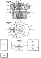
- the gyroscopic device comprises a router 1, enclosed in a housing 2 and capable of being rotated around its shaft 3 of axis ZZ 'by an electric motor 4 housed in said housing (see figure 4).
- the housing 2 comprises aligned pins 5 and 6, allowing it to pivot about the pitch axis Y-Y 'of the vehicle (not shown) on which said gyroscopic device is mounted.
- the pins 5 and 6 are used to articulate the housing 2 and its router 1 on a frame 7, itself articulated around the roll axis X-X 'of said vehicle.
- the frame 7 is not shown in FIG. 4.
- the supply and control connections of the motor 4 pass, in a known manner, through the pins 5 and 6 of the axis Y-Y 'and those (not shown) of the axis X-X' of the frame 7.
- the roll suspension frame 7 is integral with a cylindrical cam 8 on which rolls a roller 9 mounted free in rotation on an arm 10 articulated on an axis 11 integral with the housing 2 of said gyroscopic device.
- the cam 8 is centered on the roll axis X-X '.
- a spring 12 hooked between the end of the arm 10 opposite the roller 9, and said housing tends to apply with a determined force the roller 9 against the operating surface of the cam (position in dotted lines in FIG. 1).
- the shape of the cam 8 is such that when said roller 9 presses on its operative surface, the frame 7 is automatically brought back and maintained at the relative horizontal of the housing 2 (zero roll).
- An electromagnet 13 is capable of suppressing the action of the roller 9 when it is activated, by attracting against its frame 13a the arm 10 supporting the roller 9.
- the frame 13a and the winding 13b are made integral with the housing 2 by a casing 14.
- the roll frame 7 is free and, consequently, the router 1 is also free in roll.
- the roller 9 is applied to the cam 8 and causes said frame 7 and said router 1 to return and remain in the horizontal position relative to the machine supporting the gyroscopic device.
- the electromagnet 13 is activated in synchronism with the launching of the router by the motor 4.
- This spiral movement at start-up is caused by the component, around the axis XX ', of the reaction torque of the router motor 4, this component being all the more important as the angular difference around the axis YY 'is important when the motor is switched on 4.
- the set-up time of a vertical gyroscopic device reaches ten minutes.
- a delay t1 (of approximately 3 seconds for example) before releasing the frame 7 from the gyroscope and after having launched the router 1, the spiral movement is initially suppressed, thanks to the existence of the restoring torque around the axis XX ', which prevents the initiation of this spiral movement, while the angular momentum is still too low to ensure the stability of the gyroscope.
- the difference that is to say the gain on the stationing time, is a very important parameter in the case of an anti-ship weapon system for example, for which the reaction time of the system can constitute a decisive parameter.
- the introduction of the delay t1 on the same gyroscope reduces the set-up time from around ten minutes to around 2 minutes, which constitutes an interesting concrete result.
- the advantage is even more noticeable in the case of using the gyroscope on a carrier vehicle in oscillating motion with large angular amplitudes during the starting of the gyroscope (boat, plane or helicopter for example), because in this case, the 'resulting tilt at start around the XX axis' can bring the gyroscope into a configuration where its erection system can be made ineffective - or in any case, very ineffective -, which leads to a set-up time prohibitive, whereas, according to the invention, the gyroscope remains usable with a set-up time of a few minutes, even with a support having oscillation amplitudes of 30 ° around the horizontal.
- FIGS. 2 to 5 a known erector mechanism for a gyroscopic device has been illustrated, the roll return device 8 to 14 not being shown in these figures.
- this erector mechanism for a vertical gyroscopic device essentially comprises an unstable pendulum 15 articulated around the axis of rotation ZZ of the router 1, this unstable pendulum being driven in the same direction as the router 1 by a gear reducer 16 which is driven from the shaft 3 and which rotates at a constant speed of approximately 40 revolutions per minute, when the router rotates for example at 23,000 revolutions per minute, a counterweight 17 similar in shape to pendulum 1, articulated around the same axis, and above all of equivalent mass, so as to constitute with it a set whose center of gravity is located on the axis of rotation ZZ 'of the router, when the pendulum is unstable 15 is aligned with the counterweight 17.
- the latter case is carried out when the gyroscope is stabilized vertically and the erection system then does not apply any torque to the gyroscope. This is the case illustrated schematically in FIG. 2.
- the unstable pendulum 15 In its plane of rotation, perpendicular to the axis of rotation ZZ of the router 1, the unstable pendulum 15 has a freedom of angular movement between, on the one hand, a drive stop 18 which positions it at alignment with its counterweight 17, and, on the other hand, a front stop 19 which limits its free travel in the direction of the rotational movement of the gyroscopic system.
- the supply connections of the coil 20 are routed to the outside of the gyroscope suspension passing successively through the pins 5 and 6 of the internal axis Y-Y ', then through the pins (not shown) of the suspension axis X-X '.
- the unstable pendulum 15 (which turns extremely slowly at the start of the start of the router 1) could be, for a non-negligible time, in a position where it would exert a fairly large torque on the gyroscope, which would still have only a very low angular momentum; in this case, the gyroscope could reach a very difficult - if not impossible - position to then be corrected by the erector.
- t2 For a router reaching its maximum speed after a time of 90 seconds, you can choose t2 equal to 30 seconds.
- FIG. 6 gives the block diagram of the control of the gyroscope according to the invention.
- the power supply 23 when the power supply 23 is activated by the command 24, it delivers a current to the motor 4 of the router 1, then to the electromagnet 13 deactivating the roll-back torque with 3 seconds of delay, then to l electromagnet 20 activating said erector with 30 seconds delay.
- the device according to the invention can be easily mounted on any gyroscope not intended to receive it, and in particular on simple commercial gyroscopes originally having a prohibitive shift time for use on missiles.
Landscapes
- Engineering & Computer Science (AREA)
- Physics & Mathematics (AREA)
- General Physics & Mathematics (AREA)
- Radar, Positioning & Navigation (AREA)
- Remote Sensing (AREA)
- Manufacturing & Machinery (AREA)
- Control Of Position, Course, Altitude, Or Attitude Of Moving Bodies (AREA)
- Gyroscopes (AREA)
Applications Claiming Priority (2)
| Application Number | Priority Date | Filing Date | Title |
|---|---|---|---|
| FR7922006 | 1979-09-03 | ||
| FR7922006A FR2464457A1 (fr) | 1979-09-03 | 1979-09-03 | Procede et dispositif de mise a poste d'un gyroscope de verticale |
Publications (3)
| Publication Number | Publication Date |
|---|---|
| EP0024977A2 EP0024977A2 (fr) | 1981-03-11 |
| EP0024977A3 EP0024977A3 (en) | 1981-03-18 |
| EP0024977B1 true EP0024977B1 (fr) | 1983-07-13 |
Family
ID=9229307
Family Applications (1)
| Application Number | Title | Priority Date | Filing Date |
|---|---|---|---|
| EP80401190A Expired EP0024977B1 (fr) | 1979-09-03 | 1980-08-13 | Procédé et dispositif de mise à poste d'un gyroscope de verticale |
Country Status (5)
| Country | Link |
|---|---|
| US (1) | US4346614A (show.php) |
| EP (1) | EP0024977B1 (show.php) |
| CA (1) | CA1136906A (show.php) |
| DE (1) | DE3064132D1 (show.php) |
| FR (1) | FR2464457A1 (show.php) |
Families Citing this family (1)
| Publication number | Priority date | Publication date | Assignee | Title |
|---|---|---|---|---|
| WO1983001681A1 (en) * | 1981-11-09 | 1983-05-11 | Navidyne Corp | Improved gyro-stabilized apparatus |
Family Cites Families (10)
| Publication number | Priority date | Publication date | Assignee | Title |
|---|---|---|---|---|
| US2737052A (en) * | 1956-03-06 | noxon | ||
| US2605641A (en) * | 1952-08-05 | Starting arrangement for gyro | ||
| US2891407A (en) * | 1959-06-23 | Gyroscopic apparatus | ||
| US2654254A (en) * | 1949-07-20 | 1953-10-06 | Gen Electric | Caging device for gyroscopes |
| FR1078486A (fr) * | 1952-03-14 | 1954-11-18 | Sperry Corp | Instrument gyroscopique avec dispositif de centrage et de verrouillage du cadre de support du rotor |
| US2729978A (en) * | 1952-11-18 | 1956-01-10 | Iron Fireman Mfg Co | Gyroscope caging system |
| GB761521A (en) | 1953-12-08 | 1956-11-14 | G M Giannini & Co Inc | Improvements in or relating to gyroscopes |
| US2907212A (en) * | 1957-04-03 | 1959-10-06 | Air Equipment | Gyroscopes |
| US2880618A (en) * | 1957-09-27 | 1959-04-07 | Sperry Rand Corp | Quick erecting means for gyro verticals |
| US3359807A (en) * | 1965-05-17 | 1967-12-26 | Gen Electric | Gyro erection system |
-
1979
- 1979-09-03 FR FR7922006A patent/FR2464457A1/fr active Granted
-
1980
- 1980-08-13 EP EP80401190A patent/EP0024977B1/fr not_active Expired
- 1980-08-13 DE DE8080401190T patent/DE3064132D1/de not_active Expired
- 1980-08-21 US US06/179,994 patent/US4346614A/en not_active Expired - Lifetime
- 1980-08-26 CA CA000359005A patent/CA1136906A/fr not_active Expired
Also Published As
| Publication number | Publication date |
|---|---|
| FR2464457B1 (show.php) | 1982-04-30 |
| FR2464457A1 (fr) | 1981-03-06 |
| US4346614A (en) | 1982-08-31 |
| DE3064132D1 (en) | 1983-08-18 |
| CA1136906A (fr) | 1982-12-07 |
| EP0024977A3 (en) | 1981-03-18 |
| EP0024977A2 (fr) | 1981-03-11 |
Similar Documents
| Publication | Publication Date | Title |
|---|---|---|
| EP0318359B1 (fr) | Dispositif de déploiement d'une ailette de projectile | |
| EP1484247B1 (fr) | Actionneur gyroscopique, notamment pour dispositif de pilotage de l'attitude d'un satellite | |
| EP0394897B1 (fr) | Procédé de mise à poste d'un satellite de télécommunications géostationnaire | |
| EP3201091B1 (fr) | Procédé de contrôle d'attitude d'un satellite en mode survie, satellite adapté et procédé de commande à distance d'un tel satellite | |
| EP3168149A1 (fr) | Drone ayant un support de propulsion couple | |
| FR2500617A1 (fr) | Dispositif de surete pour fusee de projectiles stabilises par rotation | |
| WO2015075237A1 (fr) | Procédé et dispositif de commande d'une phase d'acquisition du soleil par un engin spatial | |
| EP3956219B1 (fr) | Dispositif de propulsion pour aérodyne à voilure tournante et à décollage et atterrissage verticaux, et aérodyne comprenant au moins un tel dispositif de propulsion | |
| EP0024977B1 (fr) | Procédé et dispositif de mise à poste d'un gyroscope de verticale | |
| EP1695907A1 (fr) | Dispositif de verrouillage d'une structure de fixation d'une pale au moyeu d'un rotor de giravion | |
| EP4370423B1 (fr) | Dispositif de contrôle de vitesse angulaire d'un engin spatial et engin spatial correspondant | |
| EP3475764A1 (fr) | Mouvement d'horlogerie | |
| FR2689479A1 (fr) | Véhicule d'inspection et/ou d'intervention capable de se déplacer sur des parois verticales inclinées ou en plafond. | |
| FR2720806A1 (fr) | Dispositif de freinage d'un arbre rotatif, moteur et appareillage comprenant un tel dispositif. | |
| EP0047212B1 (fr) | Dispositif d'éloignement combinant un mouvement de translation et un mouvement de rotation, notamment pour un équipement sur un engin spatial | |
| WO2025190470A1 (fr) | Mouvement horloger comprenant un mécanisme de remontage automatique | |
| GB1295928A (show.php) | ||
| FR3122411A1 (fr) | Moteur à création de moment cinétique | |
| EP0019677B1 (fr) | Erecteur de gyroscope de verticale | |
| EP4680530A1 (fr) | Dispositif de contrôle de vitesse angulaire d'un engin spatial et engin spatial correspondant | |
| FR2526397A1 (fr) | Dispositif d'amortissement du mouvement de nutation pour engin ou vehicule spatial | |
| FR3113893A1 (fr) | Aéronef à voilure tournante à stator stabilisé en lacet | |
| CH229259A (fr) | Ensemble électro-moteur à réducteur de vitesse. | |
| FR2899962A1 (fr) | Etage de munition a correction terminale. | |
| FR2797946A1 (fr) | Dispositif de montage d'un appendice rigide sur un engin apte a etre lance depuis le tube, et engin correspondant |
Legal Events
| Date | Code | Title | Description |
|---|---|---|---|
| PUAI | Public reference made under article 153(3) epc to a published international application that has entered the european phase |
Free format text: ORIGINAL CODE: 0009012 |
|
| PUAL | Search report despatched |
Free format text: ORIGINAL CODE: 0009013 |
|
| AK | Designated contracting states |
Designated state(s): BE CH DE GB IT NL SE |
|
| AK | Designated contracting states |
Designated state(s): BE CH DE GB IT NL SE |
|
| 17P | Request for examination filed |
Effective date: 19810210 |
|
| ITF | It: translation for a ep patent filed | ||
| GRAA | (expected) grant |
Free format text: ORIGINAL CODE: 0009210 |
|
| AK | Designated contracting states |
Designated state(s): BE CH DE GB IT LI NL SE |
|
| REF | Corresponds to: |
Ref document number: 3064132 Country of ref document: DE Date of ref document: 19830818 |
|
| PLBE | No opposition filed within time limit |
Free format text: ORIGINAL CODE: 0009261 |
|
| STAA | Information on the status of an ep patent application or granted ep patent |
Free format text: STATUS: NO OPPOSITION FILED WITHIN TIME LIMIT |
|
| 26N | No opposition filed | ||
| NLT1 | Nl: modifications of names registered in virtue of documents presented to the patent office pursuant to art. 16 a, paragraph 1 |
Owner name: AEROSPATIALE SOCIETE NATIONALE INDUSTRIELLE TE PAR |
|
| ITTA | It: last paid annual fee | ||
| EAL | Se: european patent in force in sweden |
Ref document number: 80401190.6 |
|
| PGFP | Annual fee paid to national office [announced via postgrant information from national office to epo] |
Ref country code: CH Payment date: 19980701 Year of fee payment: 19 |
|
| PGFP | Annual fee paid to national office [announced via postgrant information from national office to epo] |
Ref country code: SE Payment date: 19980710 Year of fee payment: 19 |
|
| PGFP | Annual fee paid to national office [announced via postgrant information from national office to epo] |
Ref country code: DE Payment date: 19980730 Year of fee payment: 19 Ref country code: BE Payment date: 19980730 Year of fee payment: 19 |
|
| PGFP | Annual fee paid to national office [announced via postgrant information from national office to epo] |
Ref country code: GB Payment date: 19980804 Year of fee payment: 19 |
|
| PGFP | Annual fee paid to national office [announced via postgrant information from national office to epo] |
Ref country code: NL Payment date: 19980831 Year of fee payment: 19 |
|
| PG25 | Lapsed in a contracting state [announced via postgrant information from national office to epo] |
Ref country code: GB Free format text: LAPSE BECAUSE OF NON-PAYMENT OF DUE FEES Effective date: 19990813 |
|
| PG25 | Lapsed in a contracting state [announced via postgrant information from national office to epo] |
Ref country code: SE Free format text: THE PATENT HAS BEEN ANNULLED BY A DECISION OF A NATIONAL AUTHORITY Effective date: 19990814 |
|
| PG25 | Lapsed in a contracting state [announced via postgrant information from national office to epo] |
Ref country code: LI Free format text: LAPSE BECAUSE OF NON-PAYMENT OF DUE FEES Effective date: 19990831 Ref country code: CH Free format text: LAPSE BECAUSE OF NON-PAYMENT OF DUE FEES Effective date: 19990831 Ref country code: BE Free format text: LAPSE BECAUSE OF NON-PAYMENT OF DUE FEES Effective date: 19990831 |
|
| BERE | Be: lapsed |
Owner name: SOC. NATIONALE INDUSTRIELLE AEROSPATIALE S.A. Effective date: 19990831 |
|
| PG25 | Lapsed in a contracting state [announced via postgrant information from national office to epo] |
Ref country code: NL Free format text: LAPSE BECAUSE OF NON-PAYMENT OF DUE FEES Effective date: 20000301 |
|
| GBPC | Gb: european patent ceased through non-payment of renewal fee |
Effective date: 19990813 |
|
| REG | Reference to a national code |
Ref country code: CH Ref legal event code: PL |
|
| EUG | Se: european patent has lapsed |
Ref document number: 80401190.6 |
|
| NLV4 | Nl: lapsed or anulled due to non-payment of the annual fee |
Effective date: 20000301 |
|
| PG25 | Lapsed in a contracting state [announced via postgrant information from national office to epo] |
Ref country code: DE Free format text: LAPSE BECAUSE OF NON-PAYMENT OF DUE FEES Effective date: 20000601 |