EP0024913A1 - Electrodes for cardiac pacemakers - Google Patents
Electrodes for cardiac pacemakers Download PDFInfo
- Publication number
- EP0024913A1 EP0024913A1 EP80302946A EP80302946A EP0024913A1 EP 0024913 A1 EP0024913 A1 EP 0024913A1 EP 80302946 A EP80302946 A EP 80302946A EP 80302946 A EP80302946 A EP 80302946A EP 0024913 A1 EP0024913 A1 EP 0024913A1
- Authority
- EP
- European Patent Office
- Prior art keywords
- electrode
- atrial
- catheter
- dual
- ventricular
- Prior art date
- Legal status (The legal status is an assumption and is not a legal conclusion. Google has not performed a legal analysis and makes no representation as to the accuracy of the status listed.)
- Granted
Links
Images
Classifications
-
- A—HUMAN NECESSITIES
- A61—MEDICAL OR VETERINARY SCIENCE; HYGIENE
- A61N—ELECTROTHERAPY; MAGNETOTHERAPY; RADIATION THERAPY; ULTRASOUND THERAPY
- A61N1/00—Electrotherapy; Circuits therefor
- A61N1/02—Details
- A61N1/04—Electrodes
- A61N1/05—Electrodes for implantation or insertion into the body, e.g. heart electrode
- A61N1/056—Transvascular endocardial electrode systems
Definitions
- This invention relates to electrodes for cardiac pacemakers, and particularly to transvenous electrodes suitable for atrial sensing and ventricular pacing, for A-V sequential pacing or bifocal pacing.
- a dual electrode for use in cardiac pacemaking to enable both ventricular and atrial electrical contact to be made which comprises a catheter for insertion through a blood vessel to the heart and having at its distal end a ventricular electrode electrically-connected to the proximal end of the catheter, and, spaced apart from the ventricular electrode, at least one atrial electrode disposed in a plane transverse to the catheter and spaced radially apart therefrom, said at least one atrial electrode being supported in a material connected to said catheter which is sufficiently flexible and resilient to enable the atrial electrode(s) to be deformed out of said plane and pass through said blood vessel, said atrial electrode(s) being electrically-connected to the proximal end of the catheter.
- the electrodes are preferably formed as prongs extending outwardly from the catheter. At least two, and preferably three such prongs are employed.
- the dual electrode illustrated has a ventricular stimulating tip electrode at its distal end (not shown) and three atrial electrodes 2.
- the ventricular tip electrode employed may be any of those currently in use, for example a screw-in or contact type, with a surface shape and area as desired.
- the atrial electrodes 2 are disposed approximately 13 to 17 cms back from the tip and are radially-disposed about a central catheter 4 of electrically-insulating flexible plastics tubing.
- An insulated electrical conductor 6 which makes connection with the ventricular tip electrode passes along catheter 4 to the proximal terminal of the electrode, as is conventional.
- An electrically-conductive metal ring 8 makes contact with and circumscribes catheter 4. Electrically connected to ring 8 and passing through the catheter wall is a second insulated electrical conductor 10. Also connected to ring 8 and extending radially outwardly therefrom are three electrically-conductive metal springs 12. The springs are respectively connected to an atrial electrode 2 and enable electrical connection between the atrial electrodes 2 and conductor 10 to be made. The conductor 10 passes along catheter 4 to the proximal terminal of the electrode.
- the atrial electrodes 2 are maintained in a sheath of thin electrically-insulating flexible plastics material 14.
- the electrodes thus form three radially-disposed prongs biassed outwardly under the influence of springs 12.
- the radial length of each prong is typically from 0.5 to 1.5 cms.
- the sheath 14 is sealed to catheter 4 just beyond each side of the prongs.
- the prongs are flexible and therefore allow the entire electrode to be introduced through a vein of suitable size such as the jugular subclavian or cephalic.
- the stimulating distal tip of the electrode can be positioned in the ideal position within the right ventricle and the prongs will then make contact with the lateral wall of the right atrium even although the course of the electrical conductors 6 and 10 lies within the cavity of the right atrium, away from the wall.
- the prongs are of such flexibility as to make adequate contact with the right atrial wall at one or more points and the tips are conductive with small area electrodes.
- the stiffness of the prongs can be influenced by the sheath material chosen (such as silicone rubber), by the dimensions and shape of the prongs, or by the incorporation of central stiffness such as the springs illustrated or flexible rod of metal.
- the contact tips of the prongs can be shaped with a small radius of curvature to provide a high current density and pacing will occur through whichever of the prongs is contacting the atrial wall.
- the prongs can alt-ernatively be made conducting themselves, for example, by "filling" the insulating material 14 with biocompatible conducting elements such as carbon, or by surface coating with a flexible conducting layer of biocompatible material, such as gold.
- the sheath 14 might only be sealed to the catheter 4 on the distal side of the prongs. On the proximal side the sheath 14 could then extend to the proximal end of the electrode with the conductor 10 extending to the proximal end in the annular gap between catheter 4 and sheath 14. In this manner, catheter 4 need not be pierced to allow passage of conductor 10 therethrough and, indeed, the insulation of one or both of conductors 6 and 10 could be omitted if desired.
- the invention is not restricted to the use of three atrial electrodes and more, or less prongs could be employed if wished, although 3, in the configuration illustrated, is thought to be the optimum.
- a single continuous atrial electrode, spaced apart from and circumscribing catheter 4 may be employed.
- the atrial electrode would be similar to a small floppy disc extending outwardly from catheter 4.
- a coaxial cable with twin coaxial conductors may be employed.
Abstract
Description
- This invention relates to electrodes for cardiac pacemakers, and particularly to transvenous electrodes suitable for atrial sensing and ventricular pacing, for A-V sequential pacing or bifocal pacing.
- There are many occasions when it is desirable to control an artificial cardiac pacemaker by physiological methods, or to maintain physiological atrial-ventricular timing during pacing. Such instances include detection of activity from the sinus node or the atrium (right or left) using this activity to activate a cardiac pacemaker with subsequent delivery of a stimulus to the ventricle (right or left), or to another suitable pacing site. A delay may be incorporated between sensing the supraventricular impulse and delivery of the ventricular stimulating impulse.
- Under other circumstances, it may be desirable to pace both the atrium and the ventricle, with or without any intervening delay.
- Present techniques for reliable sensing of supraventricular impulses usually rely on attachment of a separate sensing electrode placed independently from the stimulating electrode. Dual electrodes for sensing the atrium and pacing the ventricle are so far unreliable.
- It is extremely difficult to pace the atrium or adjoining tissues, such as the sinus node, unless a separate electrode is attached so that A-V sequential pacing requires complicated electrode placement.
- I have now developed a transvenous dual electrode suitable for the above applications and which can be reliably and simply placed in position.
- According to the invention I provide a dual electrode for use in cardiac pacemaking to enable both ventricular and atrial electrical contact to be made, which comprises a catheter for insertion through a blood vessel to the heart and having at its distal end a ventricular electrode electrically-connected to the proximal end of the catheter, and, spaced apart from the ventricular electrode, at least one atrial electrode disposed in a plane transverse to the catheter and spaced radially apart therefrom, said at least one atrial electrode being supported in a material connected to said catheter which is sufficiently flexible and resilient to enable the atrial electrode(s) to be deformed out of said plane and pass through said blood vessel, said atrial electrode(s) being electrically-connected to the proximal end of the catheter.
- The electrodes are preferably formed as prongs extending outwardly from the catheter. At least two, and preferably three such prongs are employed.
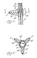
- Preferred features of the present invention will now be described with reference to the accompanying drawing, given by way of example, wherein:-
- Figure 1 is a cross-section through a dual electrode of the invention with the ventricular stimulating tip omitted, and
- Figure 2 is a section along the line X-X of Figure 1.
- Referring to the drawing, the dual electrode illustrated has a ventricular stimulating tip electrode at its distal end (not shown) and three
atrial electrodes 2. The ventricular tip electrode employed may be any of those currently in use, for example a screw-in or contact type, with a surface shape and area as desired. Theatrial electrodes 2 are disposed approximately 13 to 17 cms back from the tip and are radially-disposed about a central catheter 4 of electrically-insulating flexible plastics tubing. An insulatedelectrical conductor 6 which makes connection with the ventricular tip electrode passes along catheter 4 to the proximal terminal of the electrode, as is conventional. - An electrically-
conductive metal ring 8 makes contact with and circumscribes catheter 4. Electrically connected toring 8 and passing through the catheter wall is a second insulatedelectrical conductor 10. Also connected toring 8 and extending radially outwardly therefrom are three electrically-conductive metal springs 12. The springs are respectively connected to anatrial electrode 2 and enable electrical connection between theatrial electrodes 2 andconductor 10 to be made. Theconductor 10 passes along catheter 4 to the proximal terminal of the electrode. - The
atrial electrodes 2 are maintained in a sheath of thin electrically-insulatingflexible plastics material 14. The electrodes thus form three radially-disposed prongs biassed outwardly under the influence ofsprings 12. The radial length of each prong is typically from 0.5 to 1.5 cms. Thesheath 14 is sealed to catheter 4 just beyond each side of the prongs. - The prongs are flexible and therefore allow the entire electrode to be introduced through a vein of suitable size such as the jugular subclavian or cephalic. The stimulating distal tip of the electrode can be positioned in the ideal position within the right ventricle and the prongs will then make contact with the lateral wall of the right atrium even although the course of the
electrical conductors - The prongs are of such flexibility as to make adequate contact with the right atrial wall at one or more points and the tips are conductive with small area electrodes. The stiffness of the prongs can be influenced by the sheath material chosen (such as silicone rubber), by the dimensions and shape of the prongs, or by the incorporation of central stiffness such as the springs illustrated or flexible rod of metal.
- The contact tips of the prongs can be shaped with a small radius of curvature to provide a high current density and pacing will occur through whichever of the prongs is contacting the atrial wall.
- The prongs can alt-ernatively be made conducting themselves, for example, by "filling" the insulating
material 14 with biocompatible conducting elements such as carbon, or by surface coating with a flexible conducting layer of biocompatible material, such as gold. - Various modifications to the dual electrode described are possible. For example, the
sheath 14 might only be sealed to the catheter 4 on the distal side of the prongs. On the proximal side thesheath 14 could then extend to the proximal end of the electrode with theconductor 10 extending to the proximal end in the annular gap between catheter 4 andsheath 14. In this manner, catheter 4 need not be pierced to allow passage ofconductor 10 therethrough and, indeed, the insulation of one or both ofconductors - The invention is not restricted to the use of three atrial electrodes and more, or less prongs could be employed if wished, although 3, in the configuration illustrated, is thought to be the optimum.
- In place of separate, radially-extending electrodes a single continuous atrial electrode, spaced apart from and circumscribing catheter 4, may be employed. In this embodiment the atrial electrode would be similar to a small floppy disc extending outwardly from catheter 4.
- furthermore, in place of separate conductors for the atrial and ventricular electrodes, a coaxial cable with twin coaxial conductors may be employed.
Claims (7)
Priority Applications (1)
| Application Number | Priority Date | Filing Date | Title |
|---|---|---|---|
| AT80302946T ATE4861T1 (en) | 1979-08-28 | 1980-08-26 | PACEMAKER ELECTRODES. |
Applications Claiming Priority (2)
| Application Number | Priority Date | Filing Date | Title |
|---|---|---|---|
| GB7929735 | 1979-08-28 | ||
| GB7929735 | 1979-08-28 |
Publications (2)
| Publication Number | Publication Date |
|---|---|
| EP0024913A1 true EP0024913A1 (en) | 1981-03-11 |
| EP0024913B1 EP0024913B1 (en) | 1983-10-05 |
Family
ID=10507448
Family Applications (1)
| Application Number | Title | Priority Date | Filing Date |
|---|---|---|---|
| EP80302946A Expired EP0024913B1 (en) | 1979-08-28 | 1980-08-26 | Electrodes for cardiac pacemakers |
Country Status (4)
| Country | Link |
|---|---|
| US (1) | US4386615A (en) |
| EP (1) | EP0024913B1 (en) |
| AT (1) | ATE4861T1 (en) |
| DE (1) | DE3065166D1 (en) |
Cited By (4)
| Publication number | Priority date | Publication date | Assignee | Title |
|---|---|---|---|---|
| EP0159753A1 (en) * | 1984-04-16 | 1985-10-30 | Eliezer A. Astrinski | Cardiac lead |
| EP0366793A1 (en) * | 1987-06-25 | 1990-05-09 | Terumo Kabushiki Kaisha | Catheter provided with built-in conductive wire |
| WO1992009330A1 (en) * | 1990-11-21 | 1992-06-11 | Intermedics, Inc. | Pacer lead with bipolar electrode |
| US5674274A (en) * | 1995-12-14 | 1997-10-07 | Pacesetter, Inc. | Implantable adjustable single-pass A-V lead for use with an implantable stimulation device |
Families Citing this family (17)
| Publication number | Priority date | Publication date | Assignee | Title |
|---|---|---|---|---|
| US4497326A (en) * | 1981-04-06 | 1985-02-05 | Curry Paul V L | Heart pacing lead |
| US5423878A (en) * | 1984-03-06 | 1995-06-13 | Ep Technologies, Inc. | Catheter and associated system for pacing the heart |
| US4608986A (en) * | 1984-10-01 | 1986-09-02 | Cordis Corporation | Pacing lead with straight wire conductors |
| US5231995A (en) * | 1986-11-14 | 1993-08-03 | Desai Jawahar M | Method for catheter mapping and ablation |
| US5215103A (en) * | 1986-11-14 | 1993-06-01 | Desai Jawahar M | Catheter for mapping and ablation and method therefor |
| US6738673B2 (en) | 1986-11-14 | 2004-05-18 | Jawahar M. Desai | Method for catheter mapping and ablation |
| US5365926A (en) * | 1986-11-14 | 1994-11-22 | Desai Jawahar M | Catheter for mapping and ablation and method therefor |
| AU8627091A (en) * | 1990-09-10 | 1992-03-30 | Ep Technologies Inc | Apparatus for pacing an in vivo heart |
| US5433729A (en) * | 1991-04-12 | 1995-07-18 | Incontrol, Inc. | Atrial defibrillator, lead systems, and method |
| US5922014A (en) | 1997-09-02 | 1999-07-13 | Medtronic, Inc. | Single pass lead and method of use |
| US5991668A (en) * | 1997-09-25 | 1999-11-23 | Medtronic, Inc. | Medical electrical lead |
| US6148238A (en) * | 1998-08-10 | 2000-11-14 | Medtronic, Inc. | Pacing leads having a brachiocephalic tine or star tine |
| WO2009051882A1 (en) * | 2007-10-16 | 2009-04-23 | Cardiac Pacemakers, Inc. | Stimulation and sensing lead wtih non-coiled wire construction |
| WO2009079037A1 (en) | 2007-12-14 | 2009-06-25 | Cardiac Pacemakers, Inc. | Fixation helix and multipolar medical electrode |
| US9480834B2 (en) | 2012-05-08 | 2016-11-01 | Cardiac Pacemakers, Inc. | Multipolar conductor for an implantable medical device |
| US9072864B2 (en) | 2012-11-28 | 2015-07-07 | Ad-Tech Medical Instrument Corporation | Catheter with depth electrode for dual-purpose use |
| US9750422B2 (en) * | 2014-02-12 | 2017-09-05 | Biosense Webster (Israel) Ltd | Catheter with transverse branches |
Citations (6)
| Publication number | Priority date | Publication date | Assignee | Title |
|---|---|---|---|---|
| GB1337670A (en) * | 1970-12-28 | 1973-11-21 | American Optical Corp | Electrode for atrial pacing |
| DE2358883A1 (en) * | 1972-11-28 | 1974-06-12 | Thomas A Preston | SINGLE WIRE CATHETER DEVICE AND PACEMAKING PROCEDURE |
| US3865118A (en) * | 1973-12-27 | 1975-02-11 | Univ California | Transvenous coaxial catheter |
| US3935864A (en) * | 1973-07-04 | 1976-02-03 | Hans Lagergren | Endocardial electrode |
| US3981309A (en) * | 1974-12-23 | 1976-09-21 | American Optical Corporation | Patient stimulating pacer electrode |
| DE2605590A1 (en) * | 1976-02-12 | 1977-08-18 | Heinz Dr Med Praeuer | Pacemaker electrode with flexible electrode catheter - with flexible projecting base for abutment against wall of heart |
Family Cites Families (2)
| Publication number | Priority date | Publication date | Assignee | Title |
|---|---|---|---|---|
| US3348548A (en) * | 1965-04-26 | 1967-10-24 | William M Chardack | Implantable electrode with stiffening stylet |
| US3949757A (en) * | 1974-05-13 | 1976-04-13 | Sabel George H | Catheter for atrio-ventricular pacemaker |
-
1980
- 1980-08-04 US US06/175,346 patent/US4386615A/en not_active Expired - Lifetime
- 1980-08-26 DE DE8080302946T patent/DE3065166D1/en not_active Expired
- 1980-08-26 EP EP80302946A patent/EP0024913B1/en not_active Expired
- 1980-08-26 AT AT80302946T patent/ATE4861T1/en not_active IP Right Cessation
Patent Citations (7)
| Publication number | Priority date | Publication date | Assignee | Title |
|---|---|---|---|---|
| GB1337670A (en) * | 1970-12-28 | 1973-11-21 | American Optical Corp | Electrode for atrial pacing |
| DE2358883A1 (en) * | 1972-11-28 | 1974-06-12 | Thomas A Preston | SINGLE WIRE CATHETER DEVICE AND PACEMAKING PROCEDURE |
| US3935864A (en) * | 1973-07-04 | 1976-02-03 | Hans Lagergren | Endocardial electrode |
| US3935864B1 (en) * | 1973-07-04 | 1988-11-08 | Endocardial electrode | |
| US3865118A (en) * | 1973-12-27 | 1975-02-11 | Univ California | Transvenous coaxial catheter |
| US3981309A (en) * | 1974-12-23 | 1976-09-21 | American Optical Corporation | Patient stimulating pacer electrode |
| DE2605590A1 (en) * | 1976-02-12 | 1977-08-18 | Heinz Dr Med Praeuer | Pacemaker electrode with flexible electrode catheter - with flexible projecting base for abutment against wall of heart |
Cited By (7)
| Publication number | Priority date | Publication date | Assignee | Title |
|---|---|---|---|---|
| EP0159753A1 (en) * | 1984-04-16 | 1985-10-30 | Eliezer A. Astrinski | Cardiac lead |
| EP0366793A1 (en) * | 1987-06-25 | 1990-05-09 | Terumo Kabushiki Kaisha | Catheter provided with built-in conductive wire |
| EP0366793A4 (en) * | 1987-06-25 | 1990-12-12 | Terumo Kabushiki Kaisha | Catheter provided with built-in conductive wire |
| US5092333A (en) * | 1987-06-25 | 1992-03-03 | Kouji Tsuchida | Catheter accommodating electrical wires |
| WO1992009330A1 (en) * | 1990-11-21 | 1992-06-11 | Intermedics, Inc. | Pacer lead with bipolar electrode |
| US5190052A (en) * | 1990-11-21 | 1993-03-02 | Intermedics, Inc. | Pacer lead with bipolar electrode |
| US5674274A (en) * | 1995-12-14 | 1997-10-07 | Pacesetter, Inc. | Implantable adjustable single-pass A-V lead for use with an implantable stimulation device |
Also Published As
| Publication number | Publication date |
|---|---|
| ATE4861T1 (en) | 1983-10-15 |
| US4386615A (en) | 1983-06-07 |
| EP0024913B1 (en) | 1983-10-05 |
| DE3065166D1 (en) | 1983-11-10 |
Similar Documents
| Publication | Publication Date | Title |
|---|---|---|
| US4386615A (en) | Electrodes for cardiac pacemakers | |
| US4030508A (en) | Low output electrode for cardiac pacing | |
| US5545201A (en) | Bipolar active fixation lead for sensing and pacing the heart | |
| US5330520A (en) | Implantable electrode and sensor lead apparatus | |
| US7027852B2 (en) | Lead with distal tip surface electrodes connected in parallel | |
| EP0428279B1 (en) | Braid electrode leads and catheters for using the same | |
| CA1150775A (en) | Trailing tine electrode lead | |
| EP0191238B1 (en) | Pacemaker lead with enhanced sensitivity | |
| US7412289B2 (en) | Multi-electrode lead | |
| US5578068A (en) | Medical electrical lead with radially asymmetric tip | |
| US7212870B1 (en) | Dual helix active fixation stimulation lead | |
| US5265623A (en) | Optimized field defibrillation catheter | |
| US5466254A (en) | Coronary sinus lead with atrial sensing capability | |
| US7711437B1 (en) | Lead fixation device | |
| US3804098A (en) | Body implantable lead | |
| US3788329A (en) | Body implantable lead | |
| US5431681A (en) | Combination pacing and defibrillating lead having sensing capability | |
| JPH0216768Y2 (en) | ||
| US4458695A (en) | Multipolar electrode assembly for pacing lead | |
| US5545204A (en) | Sequential cardiostimulation system (DDD) using a single electrocatheter inserted through the coronary sinus | |
| EP2092955B1 (en) | Leads for pacing and/or sensing the heart from within the coronary veins | |
| US10271752B2 (en) | Detection/stimulation microlead implantable in a vessel of the venous, arterial or lymphatic network | |
| US7305270B1 (en) | Cardiac pacing/sensing lead providing far-field signal rejection | |
| EP0526671A1 (en) | Unitary intravascular defibrillating catheter with separate bipolar sensing | |
| WO2003041792A2 (en) | High impedance drug eluting cardiac lead |
Legal Events
| Date | Code | Title | Description |
|---|---|---|---|
| PUAI | Public reference made under article 153(3) epc to a published international application that has entered the european phase |
Free format text: ORIGINAL CODE: 0009012 |
|
| AK | Designated contracting states |
Designated state(s): AT BE CH DE FR GB IT LI NL SE |
|
| 17P | Request for examination filed |
Effective date: 19810821 |
|
| ITF | It: translation for a ep patent filed |
Owner name: STUDIO TORTA SOCIETA' SEMPLICE |
|
| GRAA | (expected) grant |
Free format text: ORIGINAL CODE: 0009210 |
|
| RAP1 | Party data changed (applicant data changed or rights of an application transferred) |
Owner name: AMERICAN PACEMAKER CORPORATION |
|
| AK | Designated contracting states |
Designated state(s): AT BE CH DE FR GB IT LI NL SE |
|
| REF | Corresponds to: |
Ref document number: 4861 Country of ref document: AT Date of ref document: 19831015 Kind code of ref document: T |
|
| ET | Fr: translation filed | ||
| REF | Corresponds to: |
Ref document number: 3065166 Country of ref document: DE Date of ref document: 19831110 |
|
| PLBE | No opposition filed within time limit |
Free format text: ORIGINAL CODE: 0009261 |
|
| STAA | Information on the status of an ep patent application or granted ep patent |
Free format text: STATUS: NO OPPOSITION FILED WITHIN TIME LIMIT |
|
| PGFP | Annual fee paid to national office [announced via postgrant information from national office to epo] |
Ref country code: FR Payment date: 19840824 Year of fee payment: 5 Ref country code: DE Payment date: 19840824 Year of fee payment: 5 |
|
| PGFP | Annual fee paid to national office [announced via postgrant information from national office to epo] |
Ref country code: CH Payment date: 19840910 Year of fee payment: 5 |
|
| PGFP | Annual fee paid to national office [announced via postgrant information from national office to epo] |
Ref country code: SE Payment date: 19840930 Year of fee payment: 5 Ref country code: BE Payment date: 19840930 Year of fee payment: 5 |
|
| 26N | No opposition filed | ||
| PGFP | Annual fee paid to national office [announced via postgrant information from national office to epo] |
Ref country code: AT Payment date: 19850819 Year of fee payment: 6 |
|
| PGFP | Annual fee paid to national office [announced via postgrant information from national office to epo] |
Ref country code: NL Payment date: 19850831 Year of fee payment: 6 |
|
| PG25 | Lapsed in a contracting state [announced via postgrant information from national office to epo] |
Ref country code: AT Effective date: 19860826 |
|
| PG25 | Lapsed in a contracting state [announced via postgrant information from national office to epo] |
Ref country code: SE Effective date: 19860827 |
|
| PG25 | Lapsed in a contracting state [announced via postgrant information from national office to epo] |
Ref country code: LI Effective date: 19860831 Ref country code: CH Effective date: 19860831 |
|
| BERE | Be: lapsed |
Owner name: AMERICAN PACEMAKER CORP. Effective date: 19860831 |
|
| PG25 | Lapsed in a contracting state [announced via postgrant information from national office to epo] |
Ref country code: NL Effective date: 19870301 |
|
| NLV4 | Nl: lapsed or anulled due to non-payment of the annual fee | ||
| GBPC | Gb: european patent ceased through non-payment of renewal fee | ||
| PG25 | Lapsed in a contracting state [announced via postgrant information from national office to epo] |
Ref country code: FR Free format text: LAPSE BECAUSE OF NON-PAYMENT OF DUE FEES Effective date: 19870430 |
|
| REG | Reference to a national code |
Ref country code: CH Ref legal event code: PL |
|
| PG25 | Lapsed in a contracting state [announced via postgrant information from national office to epo] |
Ref country code: DE Effective date: 19870501 |
|
| REG | Reference to a national code |
Ref country code: FR Ref legal event code: ST |
|
| PG25 | Lapsed in a contracting state [announced via postgrant information from national office to epo] |
Ref country code: GB Effective date: 19881118 |
|
| PG25 | Lapsed in a contracting state [announced via postgrant information from national office to epo] |
Ref country code: BE Effective date: 19890831 |
|
| EUG | Se: european patent has lapsed |
Ref document number: 80302946.1 Effective date: 19870812 |