EP0024822B1 - Apparatus for developing electrostatic latent images - Google Patents
Apparatus for developing electrostatic latent images Download PDFInfo
- Publication number
- EP0024822B1 EP0024822B1 EP80302596A EP80302596A EP0024822B1 EP 0024822 B1 EP0024822 B1 EP 0024822B1 EP 80302596 A EP80302596 A EP 80302596A EP 80302596 A EP80302596 A EP 80302596A EP 0024822 B1 EP0024822 B1 EP 0024822B1
- Authority
- EP
- European Patent Office
- Prior art keywords
- magnetic
- tubular member
- development
- image areas
- image
- Prior art date
- Legal status (The legal status is an assumption and is not a legal conclusion. Google has not performed a legal analysis and makes no representation as to the accuracy of the status listed.)
- Expired
Links
Images

Classifications
-
- G—PHYSICS
- G03—PHOTOGRAPHY; CINEMATOGRAPHY; ANALOGOUS TECHNIQUES USING WAVES OTHER THAN OPTICAL WAVES; ELECTROGRAPHY; HOLOGRAPHY
- G03G—ELECTROGRAPHY; ELECTROPHOTOGRAPHY; MAGNETOGRAPHY
- G03G15/00—Apparatus for electrographic processes using a charge pattern
- G03G15/06—Apparatus for electrographic processes using a charge pattern for developing
- G03G15/08—Apparatus for electrographic processes using a charge pattern for developing using a solid developer, e.g. powder developer
- G03G15/09—Apparatus for electrographic processes using a charge pattern for developing using a solid developer, e.g. powder developer using magnetic brush
Definitions
- This invention relates to an apparatus for developing electrostatic latent images. Such images are recorded on a surface having image areas and non-image areas thereon.
- U.S. Patent No. 3,176,652 issued to Mott et al. in 1965 discloses a developing apparatus comprising an elongated magnet disposed interiorly of a rotatably mounted cylindrical shield.
- the shield is non-magnetic and may be electrically insulating.
- U.S. Patent No. 3,608,522 issued to Davidson in 1971 describes a pair of magnetic rollers. Each magnetic roller comprises an outer cylinder of non-magnetic material with an elongated bar magnet being disposed interiorly of each cylinder.
- U.S. Patent No. 3,950,089 issued to Fraser et al. in 1976 discloses a magnetic brush development system having a rotatably driven applicator roll.
- the applicator roll includes a magnet disposed within a conductive sleeve coated or held in intimate contact with a sheet of highly resistive material.
- U.S. Patent No. 4 086 873 issued to Morita et al in 1978 shows a magnetic brush development system comprising a conductive cylindrical member having a layer of high insulation material coated thereon. The resistivity of the insulating layer ranges from about 10 8 to about 10 15 ohms centimeter.
- Japanese Patent Application No. 52-100746 discloses a development system including a magnetic roll disposed interiorly of a sleeve. The sleeve is made from a double layered structure with the outer layer being a non-magnetic conductive cylinder and the inner-layer being a non-magnetic insulating member.
- German Patent Specification No. DE-A-1772876 there is described a xerographic apparatus in which development is carried out by two successive magnetic brush development devices, biased to different electrical potentials. The first of these devices is so biased as to recharge incorrectly charged developer particles, and the second to deposit correctly charged particles and remove them from non-image areas.
- the present invention is intended to provide an apparatus for developing electrostatic latent images on a surface which is of simple construction yet which improves development.
- the invention is characterised by first magnetic brush development means, including conductive means and means for electrically biasing the conductive means on which a magnetic brush is formed to a voltage intermediate the voltages of the image and non-image areas, for transporting an electro-stato- graphic developer material into contact with the surface so as to optimize development of solid areas within the image areas, and second magnetic brush development means spaced from the first development means and including grounded resistive or insulating means on which a magnetic brush is formed, for transporting the developer material into contact with the surface to remove developer material from the non-image areas and to develop the lines in the image areas.
- the electrophotographic printing machine employs a belt 10 having a photoconductive surface 12 deposited on a conductive substrate 14.
- photoconductive surface 12 comprises a transport layer containing small molecules of m-TBD dispersed in a polycarbonate and a generation layer of trigonal selenium.
- Conductive substrate 14 is made preferably from aluminized Mylar (Trade Mark) which is electrically grounded.
- Belt 10 moves in the direction of arrow 16 to advance successive portions of photoconductive surface 12 through the various processing stations disposed about the path of movement thereof.
- Belt 10 is entrained about stripping roller 18, tension roller 20, and drive roller 22.
- Drive roller 22 is mounted rotatably and in engagement with belt 10.
- Roller 22 is coupled to motor 24 by suitable means such as a belt drive.
- Drive roller 22 includes a pair of opposed spaced edge guides.
- the edge guides define a space therebetween which determines the desired path of movement for belt 10.
- Belt 10 is maintained in tension by a pair of springs (not shown) resiliently urging tension roller 20 against belt 10 with the desired spring force.
- Both stripping roller 18 and tension roller 20 are mounted rotatably. These rollers are idlers which rotate freely as belt 10 moves in the direction of arrow 16.
- a corona generating device indicated generally by the reference numeral 26 charges photoconductive surface 12 of belt 10 to a relatively high, substantially uniform potential.
- the charged portion of photoconductive surface 12 is advanced through exposure station B.
- an original document 28 is positioned face-down upon transparent platen 30.
- Lamps 32 flash light rays onto original document 28.
- the light rays reflected from original document 28 are transmitted through lens 34 forming a light image thereof.
- Lens 34 focuses the light image onto the charged portion of photoconductive surface 12 to selectively dissipate the charge thereon. This records image areas and non-image areas on photoconductive surface 12.
- the image areas correspond to the informational areas contained within the original document with the non-image areas being unwanted background regions.
- a magnetic brush development system transports a developer composition of carrier granules and toner particles into contact with phoconductive surface 12.
- magnetic brush development system 36 includes two magnetic brush rollers 38 and 40. These rollers each advance the developer composition into contact with photoconductive surface 12.
- Each developer roller forms a chain-like array of developer material extending outwardly therefrom.
- the toner particles are attracted from the carrier granules to the image areas forming a toner powder image on photoconductive surface 12 of belt 10.
- Belt 10 then advances the toner powder image to transfer station D.
- a sheet of support material 42 is moved into contact with the toner powder image.
- the sheet of support material is advanced to transfer station D by a sheet feeding apparatus 44.
- sheet feeding apparatus 44 includes a feed roll 46 contacting the uppermost sheet of stack 48. Feed roll 46 rotates so as to advance the uppermost sheet from stack 48 into chute 50. Chute 50 directs the advancing sheet of support material into contact with photoconductive surface 12 of belt 10 in a timed sequence so that the toner powder image developed thereon contacts the advancing sheet of support material at transfer station D.
- Transfer station D includes a corona generating device 52 which sprays ions onto the backside of sheet 42. This attracts the toner powder image from photoconductive surface 12 to sheet 42. After transfer, the sheet continues to move in the direction of arrow 54 onto a conveyor (not shown) which advances the sheets to fusing station E.
- Fusing station E includes a fuser assembly, indicated generally by the reference numeral 56, which permanently affixes the transferred toner powder image to sheet 42.
- fuser assembly 56 includes a heated fuser roller 58 and a back-up roller 60.
- Sheet 42 passes between fuser roller 58 and back-up roller 60 with the toner powder image contacting fuser roller 58. In this manner, the toner powder image is permanently affixed to sheet 42.
- chute 62 guides the advancing sheet 42 to catch tray 64 for subsequent removal from the printing machine by the operator.
- Cleaning station F includes a preclean corona generating device (not shown) and rotatably mounted fiberous brush 66 in contact with photoconductive surface 12.
- the pre-clean corona generator neutralizes the charge attracting the particles to the photoconductive surface.
- the particles are then cleaned from photoconductive surface 12 by the rotation of brush 66 in contact therewith.
- a discharge lamp (not shown) floods photoconductive surface 12 with light to dissipate any residual electrostatic charge remaining thereon prior to the charging thereof for the next successive imaging cycle.
- FIG. 2 depicts development system 36 in greater detail.
- developer roller 38 includes a non-magnetic tubular member 68 journaled for rotation.
- tubular member 68 is made from aluminum having the exterior circumferential surface thereof roughened.
- Tubular member 68 rotates in the direction of arrow 70.
- An elongated magnetic rod 72 is positioned concentrically within tubular member 68 being spaced from the interior surface thereof.
- Magnetic rod 72 has a plurality of magnetic poles impressed thereon. The magnetic field generated by magnetic member 72 attracts the developer mixture to the exterior circumferential surface of tubular member 68.
- the developer composition is moved into contact with photoconductive surface 12.
- the image areas attract the toner particles from the carrier granules to form a powder image.
- magnetic rod 72 is preferably made from barium ferrite.
- Tubular member 68 is electrically biased by voltage source 74.
- Voltage source 74 generates a potential having a suitable polarity and magnitude to electrically bias tubular member 68 to the desired level.
- voltage source 74 electrically biases tubular member 68 to a level intermediate that of the background or non-image area voltage level and that of the image area voltage levels. In this manner, the image areas or the electrostatic latent image attracts the toner particles from the carrier granules.
- voltage source 74 electrically biases tubular member 68 with a D.C. voltage ranging from about 150 volts to about 500 volts.
- the D.C. bias level selected depends upon the background level. Hence, very frequently not only are the solid areas developed but the background areas as well have toner particles and carrier granules deposited thereon. Obviously, it is desirable to remove these background particles while maintaining the solid areas of the image developed. In addition, it is also desirable to develop any lines that may not have been developed heretofore. The foregoing is achieved by developer roller 40.
- Developer roller 40 includes a resistive or insulating non-magnetic tubular member 76. This is distinctly different from tubular member 68 which is non-magnetic and conductive.
- tubular member 76 is made from a phenolic resin having a resistivity greater than about 10 9 ohms-centimeter.
- Tubular member 76 is electrically grounded.
- An elongated magnetic rod 78 is positioned concentrically within tubular member 76 being spaced from the interior surface thereof. Magnetic rod 78 has a plurality of magnetic poles impressed thereon.
- magnetic rod 78 is made from barium ferrite.
- Tubular member 76 rotates in the direction of arrow 80.
- Blade 81 has the leading edge thereof closely adjacent to tubular member 76 so as to meter the quantity of developer material being transported thereby. Blade 81 is preferably electrically floating to maximize the insulating behavior of roll 40.
- developer roll 40 acts both to develop the lines within the image areas and to scavenge or clean up the background areas.
- Developer compositions that are particularly useful are those that comprise magnetic carrier granules having toner particles adhering thereto triboelectrically. More particularly, the carrier granules include a ferromagnetic core having a thin magnetic layer overcoated with a non-continuous layer of resinous material. Suitable resins include poly(vinylidene fluoride) and poly-(vinylidene fluoride-co-tetrafluoroethylene).
- the developer composition can be prepared by mixing the carrier granules with the toner particles. Suitable toner particles are prepared by finely grinding a resinous material and mixing it with a coloring material.
- the resinous material may be a vinyl polymer such as polyvinyl chloride, polyvinylidene chloride, polyvinyl acetate, polyvinyl acetals, polyvinyl ether, and polyacrylic.
- Suitable coloring materials may be, amongst others, chromogen black and solvent black.
- the developer comprises about 95 to 99% percent by weight of carrier and from about 5 to about 1% weight of toner, respectively.
- tubular member 76 comprises an inner-conductive cylindrical sleeve 82 having a dielectric material 84 coated thereon.
- the dielectric material may be a phenolic resin with conductive sleeve 82 being made from a non-magnetic material, such as aluminum.
- FIG. 4 there is depicted the preferred drive system for either developer roller 38 or 40.
- a constant speed motor 86 is coupled to tubular member 68.
- Tubular member 68 is mounted on suitable bearings so as to be rotatable.
- Magnetic bar 72 is mounted substantially fixed interiorly of tubular member 68. Excitation of motor 86 rotates tubular member 68 in the direction of arrow 70 ( Figure 2). In this way, the developer mixture moves also in the direction of arrow 70, i.e. in the direction opposed to the direction of motion of belt 10, as indicated by arrow 16.
- FIG. 5 there is shown motor 86 coupled to magnetic rod 72.
- magnetic rod 72 is journaled on suitable ball bearings for rotation.
- Tubular member 68 is substantially fixed and remains stationary as magnetic rod 72 rotates.
- Magnetic rod 72 is arranged to rotate in a direction opposed to arrow 70 ( Figure 2). In this way, the developer composition advances in the direction of arrow 70, i.e. opposed to the direction of movement of belt 10 as indicated by arrow 16.
- the development apparatus of the present invention optimizes solid area and line development by using two developer rollers.
- One of the developer rollers employs a conductive non-magnetic tubular member for optimizing development of solid areas.
- the other development roller utilizes an insulating tubular member to optimize line development.
- the insulating tubular member attracts thereto any particles adhering to the background areas prior to transfer of the toner powder image to the copy sheet. In this way, copy quality is optimized.
Description
- This invention relates to an apparatus for developing electrostatic latent images. Such images are recorded on a surface having image areas and non-image areas thereon.
- Heretofore, it has been difficult to develop both the large solid regions of the image areas and the lines thereof without developing the background. Frequently, solid area development resulted in the background areas attact- ing the developer mixture thereto. Ultimately, the developer mixture, in this unwanted or background region is transferred to the copy sheet resulting in a degradation of the copy quality. Different techniques have been employed to attempt to improve solid area development without developing the unwanted background regions. For example, a development electrode or screening technique is frequently employed to improve solid area development while preventing development of the background areas which have a lower potential than the solid areas. However, these systems are all rather complex and have suffered from poor development latitude resulting in low density images being formed on the copy sheets.
- Various approaches have been devised to improve development.
- U.S. Patent No. 3,176,652 issued to Mott et al. in 1965 discloses a developing apparatus comprising an elongated magnet disposed interiorly of a rotatably mounted cylindrical shield. The shield is non-magnetic and may be electrically insulating. U.S. Patent No. 3,608,522 issued to Davidson in 1971 describes a pair of magnetic rollers. Each magnetic roller comprises an outer cylinder of non-magnetic material with an elongated bar magnet being disposed interiorly of each cylinder. U.S. Patent No. 3,950,089 issued to Fraser et al. in 1976 discloses a magnetic brush development system having a rotatably driven applicator roll. As shown in Figure 3 of US 3 950 089, the applicator roll includes a magnet disposed within a conductive sleeve coated or held in intimate contact with a sheet of highly resistive material. In Figure 3, U.S. Patent No. 4 086 873 issued to Morita et al in 1978 shows a magnetic brush development system comprising a conductive cylindrical member having a layer of high insulation material coated thereon. The resistivity of the insulating layer ranges from about 108 to about 1015 ohms centimeter. Japanese Patent Application No. 52-100746 discloses a development system including a magnetic roll disposed interiorly of a sleeve. The sleeve is made from a double layered structure with the outer layer being a non-magnetic conductive cylinder and the inner-layer being a non-magnetic insulating member.
- In German Patent Specification No. DE-A-1772876 there is described a xerographic apparatus in which development is carried out by two successive magnetic brush development devices, biased to different electrical potentials. The first of these devices is so biased as to recharge incorrectly charged developer particles, and the second to deposit correctly charged particles and remove them from non-image areas.
- The present invention is intended to provide an apparatus for developing electrostatic latent images on a surface which is of simple construction yet which improves development. The invention is characterised by first magnetic brush development means, including conductive means and means for electrically biasing the conductive means on which a magnetic brush is formed to a voltage intermediate the voltages of the image and non-image areas, for transporting an electro-stato- graphic developer material into contact with the surface so as to optimize development of solid areas within the image areas, and second magnetic brush development means spaced from the first development means and including grounded resistive or insulating means on which a magnetic brush is formed, for transporting the developer material into contact with the surface to remove developer material from the non-image areas and to develop the lines in the image areas.
- One way of carrying out the invention is described in detail below with reference to the accompanying drawings which illustrate only one specific embodiment, in which:
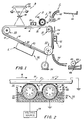
- Figure 1 is a schematic elevational view depicting an electrophotographic printing machine incorporating the features of the present invention therein;
- Figure 2 is a schematic elevational view showing the development system used in the Figure 1 printing machine;
- Figure 3 is a sectional elevational view showing another embodiment of the tubular member of the insulating developer roller used in the Figure 2 development system;
- Figure 4 shows one embodiment of the drive system of the Figure 2 development system; and
- Figure 5 shows another embodiment of the drive system of the Figure 2 development system.
- As shown in Figure 1, the electrophotographic printing machine employs a
belt 10 having aphotoconductive surface 12 deposited on aconductive substrate 14. Preferably,photoconductive surface 12 comprises a transport layer containing small molecules of m-TBD dispersed in a polycarbonate and a generation layer of trigonal selenium.Conductive substrate 14 is made preferably from aluminized Mylar (Trade Mark) which is electrically grounded.Belt 10 moves in the direction ofarrow 16 to advance successive portions ofphotoconductive surface 12 through the various processing stations disposed about the path of movement thereof.Belt 10 is entrained aboutstripping roller 18,tension roller 20, anddrive roller 22.Drive roller 22 is mounted rotatably and in engagement withbelt 10.Roller 22 is coupled tomotor 24 by suitable means such as a belt drive.Motor 24 rotatesroller 22 to advancebelt 10 in the direction ofarrow 16.Drive roller 22 includes a pair of opposed spaced edge guides. The edge guides define a space therebetween which determines the desired path of movement forbelt 10.Belt 10 is maintained in tension by a pair of springs (not shown) resiliently urgingtension roller 20 againstbelt 10 with the desired spring force. Bothstripping roller 18 andtension roller 20 are mounted rotatably. These rollers are idlers which rotate freely asbelt 10 moves in the direction ofarrow 16. - With continued reference to Figure 1, initially a portion of
belt 10 passes through charging station A. At charging station A, a corona generating device indicated generally by thereference numeral 26, chargesphotoconductive surface 12 ofbelt 10 to a relatively high, substantially uniform potential. - Next, the charged portion of
photoconductive surface 12 is advanced through exposure station B. At exposure station B, anoriginal document 28 is positioned face-down upontransparent platen 30. Lamps 32 flash light rays ontooriginal document 28. The light rays reflected fromoriginal document 28 are transmitted throughlens 34 forming a light image thereof.Lens 34 focuses the light image onto the charged portion ofphotoconductive surface 12 to selectively dissipate the charge thereon. This records image areas and non-image areas onphotoconductive surface 12. The image areas correspond to the informational areas contained within the original document with the non-image areas being unwanted background regions. - Thereafter,
belt 10 advances the electrostatic latent image recorded onphotoconductive surface 12 to development station C. At development station C, a magnetic brush development system, indicated generally by thereference numeral 36, transports a developer composition of carrier granules and toner particles into contact withphoconductive surface 12. Preferably, magneticbrush development system 36 includes twomagnetic brush rollers photoconductive surface 12. Each developer roller forms a chain-like array of developer material extending outwardly therefrom. The toner particles are attracted from the carrier granules to the image areas forming a toner powder image onphotoconductive surface 12 ofbelt 10. The detailed structure of magneticbrush development system 36 will be described hereinafter with reference to Figures 2 through 5, inclusive. -
Belt 10 then advances the toner powder image to transfer station D. At transfer station D, a sheet ofsupport material 42 is moved into contact with the toner powder image. The sheet of support material is advanced to transfer station D by a sheet feeding apparatus 44. Preferably, sheet feeding apparatus 44 includes afeed roll 46 contacting the uppermost sheet ofstack 48.Feed roll 46 rotates so as to advance the uppermost sheet fromstack 48 intochute 50.Chute 50 directs the advancing sheet of support material into contact withphotoconductive surface 12 ofbelt 10 in a timed sequence so that the toner powder image developed thereon contacts the advancing sheet of support material at transfer station D. - Transfer station D includes a
corona generating device 52 which sprays ions onto the backside ofsheet 42. This attracts the toner powder image fromphotoconductive surface 12 tosheet 42. After transfer, the sheet continues to move in the direction ofarrow 54 onto a conveyor (not shown) which advances the sheets to fusing station E. - Fusing station E includes a fuser assembly, indicated generally by the
reference numeral 56, which permanently affixes the transferred toner powder image tosheet 42. Preferably,fuser assembly 56 includes a heated fuser roller 58 and a back-up roller 60.Sheet 42 passes between fuser roller 58 and back-up roller 60 with the toner powder image contacting fuser roller 58. In this manner, the toner powder image is permanently affixed tosheet 42. After fusing,chute 62 guides the advancingsheet 42 to catchtray 64 for subsequent removal from the printing machine by the operator. - Invariably, after the sheet of support material is separated from
photoconductive surface 12 ofbelt 10, some residual particles remain adhering thereto. These residual particles are removed fromphotoconductive surface 12 at cleaning station F. Cleaning station F includes a preclean corona generating device (not shown) and rotatably mountedfiberous brush 66 in contact withphotoconductive surface 12. The pre-clean corona generator neutralizes the charge attracting the particles to the photoconductive surface. The particles are then cleaned fromphotoconductive surface 12 by the rotation ofbrush 66 in contact therewith. Subsequent to cleaning, a discharge lamp (not shown) floodsphotoconductive surface 12 with light to dissipate any residual electrostatic charge remaining thereon prior to the charging thereof for the next successive imaging cycle. - Figure 2 depicts
development system 36 in greater detail. As depicted thereat,developer roller 38 includes anon-magnetic tubular member 68 journaled for rotation. Preferably,tubular member 68 is made from aluminum having the exterior circumferential surface thereof roughened.Tubular member 68 rotates in the direction ofarrow 70. An elongatedmagnetic rod 72 is positioned concentrically withintubular member 68 being spaced from the interior surface thereof.Magnetic rod 72 has a plurality of magnetic poles impressed thereon. The magnetic field generated bymagnetic member 72 attracts the developer mixture to the exterior circumferential surface oftubular member 68. Astubular member 68 rotates in the direction ofarrow 70, the developer composition is moved into contact withphotoconductive surface 12. The image areas attract the toner particles from the carrier granules to form a powder image. By way of example,magnetic rod 72 is preferably made from barium ferrite.Tubular member 68 is electrically biased byvoltage source 74.Voltage source 74 generates a potential having a suitable polarity and magnitude to electricallybias tubular member 68 to the desired level. Preferably,voltage source 74 electrically biasestubular member 68 to a level intermediate that of the background or non-image area voltage level and that of the image area voltage levels. In this manner, the image areas or the electrostatic latent image attracts the toner particles from the carrier granules. However, inasmuch as it is highly desirable to produce good solid area coverage, the voltage level is very close to that of the background areas. By way of example,voltage source 74 electrically biasestubular member 68 with a D.C. voltage ranging from about 150 volts to about 500 volts. The D.C. bias level selected depends upon the background level. Hence, very frequently not only are the solid areas developed but the background areas as well have toner particles and carrier granules deposited thereon. Obviously, it is desirable to remove these background particles while maintaining the solid areas of the image developed. In addition, it is also desirable to develop any lines that may not have been developed heretofore. The foregoing is achieved bydeveloper roller 40. -
Developer roller 40 includes a resistive or insulating non-magnetictubular member 76. This is distinctly different fromtubular member 68 which is non-magnetic and conductive. Preferably,tubular member 76 is made from a phenolic resin having a resistivity greater than about 109 ohms-centimeter.Tubular member 76 is electrically grounded. An elongatedmagnetic rod 78 is positioned concentrically withintubular member 76 being spaced from the interior surface thereof.Magnetic rod 78 has a plurality of magnetic poles impressed thereon. By way of example,magnetic rod 78 is made from barium ferrite.Tubular member 76 rotates in the direction ofarrow 80. Astubular member 76 rotates in the direction ofarrow 80, a brush of developer mix is formed on the peripheral surface thereof. The brush of developer mix is transported into contact withphotoconductive surface 12.Blade 81 has the leading edge thereof closely adjacent totubular member 76 so as to meter the quantity of developer material being transported thereby.Blade 81 is preferably electrically floating to maximize the insulating behavior ofroll 40. - Development of the lines within the image areas is optimized by the insulating nature of
developer roll 40. In addition, any residual toner particles or carrier granules adhering to the non-image or background areas are attracted back totubular member 76. Hence, developer roll 40 acts both to develop the lines within the image areas and to scavenge or clean up the background areas. - Developer compositions that are particularly useful are those that comprise magnetic carrier granules having toner particles adhering thereto triboelectrically. More particularly, the carrier granules include a ferromagnetic core having a thin magnetic layer overcoated with a non-continuous layer of resinous material. Suitable resins include poly(vinylidene fluoride) and poly-(vinylidene fluoride-co-tetrafluoroethylene). The developer composition can be prepared by mixing the carrier granules with the toner particles. Suitable toner particles are prepared by finely grinding a resinous material and mixing it with a coloring material. By way of example, the resinous material may be a vinyl polymer such as polyvinyl chloride, polyvinylidene chloride, polyvinyl acetate, polyvinyl acetals, polyvinyl ether, and polyacrylic. Suitable coloring materials may be, amongst others, chromogen black and solvent black. The developer comprises about 95 to 99% percent by weight of carrier and from about 5 to about 1% weight of toner, respectively. These and other materials are disclosed in U.S. Patent No. 4,076,857.
- Turning now to Figure 3, there is shown another embodiment of
tubular member 76. As depicted thereat,tubular member 76 comprises an inner-conductivecylindrical sleeve 82 having adielectric material 84 coated thereon. By way of example, the dielectric material may be a phenolic resin withconductive sleeve 82 being made from a non-magnetic material, such as aluminum. - Referring now to Figure 4, there is depicted the preferred drive system for either
developer roller developer roller 38 will be described hereinafter. As shown thereat, aconstant speed motor 86 is coupled totubular member 68.Tubular member 68 is mounted on suitable bearings so as to be rotatable.Magnetic bar 72 is mounted substantially fixed interiorly oftubular member 68. Excitation ofmotor 86 rotatestubular member 68 in the direction of arrow 70 (Figure 2). In this way, the developer mixture moves also in the direction ofarrow 70, i.e. in the direction opposed to the direction of motion ofbelt 10, as indicated byarrow 16. Another embodiment of the drive system is depicted in Figure 5. - Turning now to Figure 5, there is shown
motor 86 coupled tomagnetic rod 72. In this embodiment,magnetic rod 72 is journaled on suitable ball bearings for rotation.Tubular member 68 is substantially fixed and remains stationary asmagnetic rod 72 rotates.Magnetic rod 72 is arranged to rotate in a direction opposed to arrow 70 (Figure 2). In this way, the developer composition advances in the direction ofarrow 70, i.e. opposed to the direction of movement ofbelt 10 as indicated byarrow 16. - As previously indicated, either of the embodiments depicted in Figures 4 and 5 may be used in
developer roll 40 as well asdeveloper roll 38. - In recapitulation, it is evident that the development apparatus of the present invention optimizes solid area and line development by using two developer rollers. One of the developer rollers employs a conductive non-magnetic tubular member for optimizing development of solid areas. The other development roller utilizes an insulating tubular member to optimize line development. In addition, the insulating tubular member attracts thereto any particles adhering to the background areas prior to transfer of the toner powder image to the copy sheet. In this way, copy quality is optimized.
Claims (9)
Applications Claiming Priority (2)
| Application Number | Priority Date | Filing Date | Title |
|---|---|---|---|
| US06/063,893 US4384545A (en) | 1979-08-03 | 1979-08-03 | Development system |
| US63893 | 1997-10-29 |
Publications (2)
| Publication Number | Publication Date |
|---|---|
| EP0024822A1 EP0024822A1 (en) | 1981-03-11 |
| EP0024822B1 true EP0024822B1 (en) | 1983-05-25 |
Family
ID=22052203
Family Applications (1)
| Application Number | Title | Priority Date | Filing Date |
|---|---|---|---|
| EP80302596A Expired EP0024822B1 (en) | 1979-08-03 | 1980-07-30 | Apparatus for developing electrostatic latent images |
Country Status (5)
| Country | Link |
|---|---|
| US (1) | US4384545A (en) |
| EP (1) | EP0024822B1 (en) |
| JP (1) | JPS5624375A (en) |
| CA (1) | CA1153544A (en) |
| DE (1) | DE3063480D1 (en) |
Families Citing this family (13)
| Publication number | Priority date | Publication date | Assignee | Title |
|---|---|---|---|---|
| DE3047701A1 (en) * | 1980-12-18 | 1982-07-15 | Magnetfabrik Bonn Gmbh Vorm. Gewerkschaft Windhorst, 5300 Bonn | METHOD FOR PRODUCING ANISOTROPAL PERMANENT MAGNETS AND TUBULAR PERMANENT MAGNETS PRODUCED THEREFORE |
| EP0086455B1 (en) * | 1982-02-17 | 1987-01-07 | Kabushiki Kaisha Toshiba | Developing apparatus |
| US4664504A (en) * | 1983-01-20 | 1987-05-12 | Tokyo Shibaura Denki Kabushiki Kaisha | Image forming apparatus |
| US4697913A (en) * | 1983-06-13 | 1987-10-06 | Matsushita Electric Industrial Co., Ltd. | Copying apparatus for synthesizing images |
| JPH0623895B2 (en) * | 1983-10-26 | 1994-03-30 | 株式会社東芝 | Development device |
| US4618243A (en) * | 1984-11-16 | 1986-10-21 | Xerox Corporation | Apparatus for color development with a magnetic separator containing a stationary shell with rotating magnets |
| US4872418A (en) * | 1985-10-04 | 1989-10-10 | Canon Kabushiki Kaisha | Magnet roll developing apparatus |
| JPS62179752A (en) * | 1986-02-04 | 1987-08-06 | Nec Corp | Semiconductor device |
| JPS62138455U (en) * | 1986-02-21 | 1987-09-01 | ||
| JPS6343451U (en) * | 1986-09-02 | 1988-03-23 | ||
| JPH0546280Y2 (en) * | 1987-04-20 | 1993-12-03 | ||
| US5010368A (en) * | 1990-02-20 | 1991-04-23 | Xerox Corporation | Magnetic transport roll for supplying toner or carrier and toner to a donor and magnetic developer roll respectively |
| US7366453B2 (en) * | 2005-10-31 | 2008-04-29 | Xerox Corporation | Xerographic developer unit having multiple magnetic brush rolls rotating against the photoreceptor |
Family Cites Families (6)
| Publication number | Priority date | Publication date | Assignee | Title |
|---|---|---|---|---|
| GB1006078A (en) * | 1960-09-26 | 1965-09-29 | Rank Xerox Ltd | Improved cascade development of electrostatic latent images |
| US3589895A (en) * | 1967-07-17 | 1971-06-29 | Eastman Kodak Co | Electrographic developing method suited for transfer electrophotography without cleaning |
| US3703395A (en) * | 1968-02-29 | 1972-11-21 | Eastman Kodak Co | Method for development of electrostatic images |
| US3608522A (en) * | 1969-06-04 | 1971-09-28 | Xerox Corp | Xerographic development control apparatus |
| US4086873A (en) * | 1974-07-09 | 1978-05-02 | Konishiroku Photo Industry Co., Ltd. | Electrophotographic developing device incorporating a developing electrode having an insulation layer on its surface |
| SU626710A3 (en) * | 1975-02-24 | 1978-09-30 | Ксерокс Корпорейшн (Фирма) | Apparatus for producing electrographic images with magnetic brush |
-
1979
- 1979-08-03 US US06/063,893 patent/US4384545A/en not_active Expired - Lifetime
-
1980
- 1980-06-27 CA CA000355034A patent/CA1153544A/en not_active Expired
- 1980-07-28 JP JP10351680A patent/JPS5624375A/en active Granted
- 1980-07-30 DE DE8080302596T patent/DE3063480D1/en not_active Expired
- 1980-07-30 EP EP80302596A patent/EP0024822B1/en not_active Expired
Also Published As
| Publication number | Publication date |
|---|---|
| DE3063480D1 (en) | 1983-07-07 |
| EP0024822A1 (en) | 1981-03-11 |
| US4384545A (en) | 1983-05-24 |
| CA1153544A (en) | 1983-09-13 |
| JPS6346423B2 (en) | 1988-09-14 |
| JPS5624375A (en) | 1981-03-07 |
Similar Documents
| Publication | Publication Date | Title |
|---|---|---|
| EP0024822B1 (en) | Apparatus for developing electrostatic latent images | |
| US4320958A (en) | Combined processing unit | |
| US4466732A (en) | Development system having a bounded electrical bias | |
| GB2103114A (en) | Electrostatographic reproduction | |
| EP0019380B1 (en) | Apparatus for developing a latent image | |
| US4292923A (en) | Development system | |
| EP0120688B1 (en) | A development system using a thin layer of marking particles | |
| EP0028919B1 (en) | Magnetic brush roll and developing or cleaning apparatus incorporating same | |
| EP0025671B1 (en) | Apparatus for developing an electrostatic latent image | |
| US4330193A (en) | Development system | |
| EP0036290B1 (en) | Apparatus for cleaning particles from a surface | |
| JPH0514906B2 (en) | ||
| JPH0560104B2 (en) | ||
| US4614419A (en) | Pre-development inductive charging of developer material | |
| US4297972A (en) | Development system | |
| US4324490A (en) | Development system | |
| US4240740A (en) | Development system | |
| EP0027729B1 (en) | Apparatus for developing an electrostatic latent image | |
| US4299901A (en) | Method of development | |
| US4632054A (en) | Development system | |
| JPS592059A (en) | Electrically floating developer |
Legal Events
| Date | Code | Title | Description |
|---|---|---|---|
| PUAI | Public reference made under article 153(3) epc to a published international application that has entered the european phase |
Free format text: ORIGINAL CODE: 0009012 |
|
| AK | Designated contracting states |
Designated state(s): DE FR GB |
|
| 17P | Request for examination filed |
Effective date: 19810723 |
|
| GRAA | (expected) grant |
Free format text: ORIGINAL CODE: 0009210 |
|
| AK | Designated contracting states |
Designated state(s): DE FR GB |
|
| REF | Corresponds to: |
Ref document number: 3063480 Country of ref document: DE Date of ref document: 19830707 |
|
| ET | Fr: translation filed | ||
| PLBE | No opposition filed within time limit |
Free format text: ORIGINAL CODE: 0009261 |
|
| STAA | Information on the status of an ep patent application or granted ep patent |
Free format text: STATUS: NO OPPOSITION FILED WITHIN TIME LIMIT |
|
| 26N | No opposition filed | ||
| PGFP | Annual fee paid to national office [announced via postgrant information from national office to epo] |
Ref country code: FR Payment date: 19970709 Year of fee payment: 18 |
|
| PGFP | Annual fee paid to national office [announced via postgrant information from national office to epo] |
Ref country code: GB Payment date: 19970721 Year of fee payment: 18 |
|
| PGFP | Annual fee paid to national office [announced via postgrant information from national office to epo] |
Ref country code: DE Payment date: 19970811 Year of fee payment: 18 |
|
| PG25 | Lapsed in a contracting state [announced via postgrant information from national office to epo] |
Ref country code: GB Free format text: LAPSE BECAUSE OF NON-PAYMENT OF DUE FEES Effective date: 19980730 |
|
| GBPC | Gb: european patent ceased through non-payment of renewal fee |
Effective date: 19980730 |
|
| PG25 | Lapsed in a contracting state [announced via postgrant information from national office to epo] |
Ref country code: FR Free format text: LAPSE BECAUSE OF NON-PAYMENT OF DUE FEES Effective date: 19990331 |
|
| PG25 | Lapsed in a contracting state [announced via postgrant information from national office to epo] |
Ref country code: DE Free format text: LAPSE BECAUSE OF NON-PAYMENT OF DUE FEES Effective date: 19990501 |
|
| REG | Reference to a national code |
Ref country code: FR Ref legal event code: ST |