EP0024653B2 - Apparat zur Zufuhr von Energie zu einer elektrochirurgischen Vorrichtung - Google Patents
Apparat zur Zufuhr von Energie zu einer elektrochirurgischen Vorrichtung Download PDFInfo
- Publication number
- EP0024653B2 EP0024653B2 EP80104839A EP80104839A EP0024653B2 EP 0024653 B2 EP0024653 B2 EP 0024653B2 EP 80104839 A EP80104839 A EP 80104839A EP 80104839 A EP80104839 A EP 80104839A EP 0024653 B2 EP0024653 B2 EP 0024653B2
- Authority
- EP
- European Patent Office
- Prior art keywords
- signal
- surgical
- power
- transistor
- timer
- Prior art date
- Legal status (The legal status is an assumption and is not a legal conclusion. Google has not performed a legal analysis and makes no representation as to the accuracy of the status listed.)
- Expired
Links
Images


Classifications
-
- A—HUMAN NECESSITIES
- A61—MEDICAL OR VETERINARY SCIENCE; HYGIENE
- A61B—DIAGNOSIS; SURGERY; IDENTIFICATION
- A61B18/00—Surgical instruments, devices or methods for transferring non-mechanical forms of energy to or from the body
- A61B18/04—Surgical instruments, devices or methods for transferring non-mechanical forms of energy to or from the body by heating
- A61B18/12—Surgical instruments, devices or methods for transferring non-mechanical forms of energy to or from the body by heating by passing a current through the tissue to be heated, e.g. high-frequency current
- A61B18/1206—Generators therefor
-
- A—HUMAN NECESSITIES
- A61—MEDICAL OR VETERINARY SCIENCE; HYGIENE
- A61B—DIAGNOSIS; SURGERY; IDENTIFICATION
- A61B18/00—Surgical instruments, devices or methods for transferring non-mechanical forms of energy to or from the body
- A61B18/04—Surgical instruments, devices or methods for transferring non-mechanical forms of energy to or from the body by heating
- A61B18/12—Surgical instruments, devices or methods for transferring non-mechanical forms of energy to or from the body by heating by passing a current through the tissue to be heated, e.g. high-frequency current
-
- A—HUMAN NECESSITIES
- A61—MEDICAL OR VETERINARY SCIENCE; HYGIENE
- A61B—DIAGNOSIS; SURGERY; IDENTIFICATION
- A61B18/00—Surgical instruments, devices or methods for transferring non-mechanical forms of energy to or from the body
- A61B2018/00636—Sensing and controlling the application of energy
- A61B2018/0066—Sensing and controlling the application of energy without feedback, i.e. open loop control
-
- A—HUMAN NECESSITIES
- A61—MEDICAL OR VETERINARY SCIENCE; HYGIENE
- A61B—DIAGNOSIS; SURGERY; IDENTIFICATION
- A61B18/00—Surgical instruments, devices or methods for transferring non-mechanical forms of energy to or from the body
- A61B2018/00636—Sensing and controlling the application of energy
- A61B2018/00696—Controlled or regulated parameters
- A61B2018/00761—Duration
-
- A—HUMAN NECESSITIES
- A61—MEDICAL OR VETERINARY SCIENCE; HYGIENE
- A61B—DIAGNOSIS; SURGERY; IDENTIFICATION
- A61B18/00—Surgical instruments, devices or methods for transferring non-mechanical forms of energy to or from the body
- A61B2018/00636—Sensing and controlling the application of energy
- A61B2018/00773—Sensed parameters
- A61B2018/00886—Duration
Definitions
- This invention relates to a power supply apparatus used for an electrosurgical device such as an electric scalpel.
- an electric scalpel With an electric scalpel, a local high-frequency current is caused to flow through the tissue of a living body, such as a human body, and incision and stanching are conducted by utilizing Joule heat given to the tissue by the local current.
- Such electric scalpel is provided with a plate electrode forming one pole of a high-frequency current path and a therapeutic electrode forming the other pole of the current path to supply the local current.
- the therapeutic electrode is in the form of a needle or sword having quite a narrow contact area, and the local current, i.e. a surgical current, is concentrated in close vicinity to the tissue of a living body touched by the therapeutic electrode.
- a coagulation current or surgical current for the aforesaid hemostasis or stanching is obtained by switching on and off the power circuit for a power amplifier in the power supply apparatus.
- a power amplifier for switching the required high currents there are provided vacuum tubes.
- the use of vacuum tubes requires at least one additional power source.
- high voltages are used which are transformed to high currents by means of a transformer without galvanic separation. In case of damage, the high voltages can be dangerous.
- a semiconductor switch circuit of the like can be used for switchling on and off the power circuit, too.
- This invention is contrived in consideration of the aforementioned circumstances, and it is intended to provide an apparatus for supplying power to an electrosurgical device capable of automatically limiting the energy of surgical current delivered from the electrosurgical device to a level with which the tissues of living bodies will never be incised even though a switch circuit formed of a semiconductor, etc. is broken to be rendered in an " ever-on state.
- an apparatus for supplying power to an electrosurgical device 10, 12 comprising a power output means 20 for providing a surgical current Sour, a switch means 22 for supplying said power output means 20 with a power signal Sp to provide said surgical current Sour, a first signal generation means 26 for supplying said switch means 22 with a switch signal S LF to turn on and off said switch means 22 with given timing, a second signal generation means 32 for supplying via a gate means 30 said power output means 20 with a surgical signal S HF having a period correponding to said surgical current S OUT , a timer means 28 for producing a timer signal S r for a given time Ti after being triggered ; and said gate means 30 allowing said surgical current Sour to be delivered from said power output means 20 only while said timer signal S r is being produced, wherein said timer means 28 is triggered by said switch signal S LF to produce said timer signal S ⁇ , and that said surgical current Sour is supplied from said power output means 20 to said electrosurgical device
- Fig. 1 is a block diagram for illustrating a power supply apparatus according to this invention.
- a plate electrode 10 and a therapeutic electrode 12 are connected to the secondary coil of an output transformer 16 through a capacitor 14.
- the primary coil of the output transformer 16 is coupled to a power amplifier 18.
- the amplifier 18, output transformer 16 and capacitor 14 consti- tue an output circuit (power output means) 20 for supplying a surgical current or coagulation current Sour.
- the amplifier 18 is coupled to a DC power source 24 through a switch circuit 22 and a power switch 23.
- the power source 24 may be a DC source obtained by rectifying an AC source.
- the switch circuit 22 is turned on and off in accordance with the logic level of a low-frequency signal (switch signal) S LF supplied from a low-frequency oscillator (first signal generation means) 26.
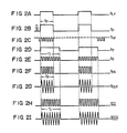
- the oscillator 26 can be formed of an astable multivibrator. For example, if the signal S LF as shown in Fig. 2A is applied to the input of the switch circuit 22, the switch circuit 22 is kept on while the logic level of the signal S LF is « 1 Faculty Then, the switch circuit 22 supplies the amplifier 18 with a power signal Sp of level V c having a pulse width of Tp as shown in Fig.2B. The amplifier 18 is supplied with power in response to the level V c of the power signal Sp, and can be activated only with such level V c . In other words, the amplifier 18 is activated by the logic « 1 » of the signal S LF .
- the signal S LF is applied as a trigger signal to the input of a timer circuit (timer means) 28.
- the timer circuit 28 is triggered a the leading edge of the signal S LF and produces a timer signal S r having a pulse width corresponding to a given time Ti as shown in Fig. 2D.
- the timer circuit 28 may, for example, be formed of a monostable multivibrator circuit. In this case, the given time Ti depends on the time constant of the multivibrator circuit.
- the timer signal S T is applied to a first input terminal of an AND gate (gate means) 30.
- the second input terminal of the AND gate 30 is supplied with a surgical signal S HF as shown in Fig.2C from a high-frequency oscillator (second signal generation means) 32.
- the surgical signal S HF is a high-frequency pulse signal having a period corresponding to the surgical current Sour and a duty factor of approximately 50 % at e.g. 500 kHz to 1 MHz.
- the AND gate 30 delivers a signal S G as shown in Fig.2E.
- the signal S G is applied to the amplifier 18 as an input signal to provide the surgical current Sour.
- the amplifier 18 is activated only when supplied power in response to the power signal Sp. Further, the amplifier 18 produces an output signal Sp A only when the input signal S G is applied thereto. Accordingly, the signal Sp A is delivered from the amplifier 18 only when the logic levels of the signal Sp and S G are both « 1 »; as shown in Fig. 2F.
- the signal S PA may be considered to be the high-frequency signal (surgical signal) S HF modulated in time by the low-frequency signal S LF .
- the amplifier 18 can be regarded as a gate circuit which, having the power signal Sp as its gate signal, receives the signal S G as an input.
- the signal Sp A is to be obtained on the basis of the logic AND of the power signal Sp, timer signal S T and surgical signal S HF or the logical AND of the switch signal S LF , timer signal S T and surgical signal S HF .
- the signal Sp A thus obtained is eliminated of its DC component through the output transformer 16 and capacitor 14, and is converted into the surgical current Sour with signal width Tp as shown in Fig. 2G.
- the current Sour is effectively used as a high-frequency cauterization current for coagulation of the tissues of living bodies.
- the surgical current Sour or the output signal Sp A is given by the logical AND of the power signal, timer signal and surgical signal. Therefore, an output current SPA and a surgical current Sour obtained when the switch circuit 22 is left ever-on have their signal duration increased from Tp to Ti, as shown in Figs. 2H and 21.
- the energy of surgical current delivered from the electrosurgical device can be limited to a level with which the tissues of living bodies will never be incised.
- Fig. 1 there is shown an indicator 38 formed of a resistor 34 and a LED 36 which are connected in parallel with a power circuit for the amplifier 18.
- the indicator 38 has a function to indicate trouble or malfunction of the switch circuit 22.
- the LED 36 goes on and off in accordance with the period of the signal Sp. If the switch circuit 22 is rendered ever-on by breakdown, the LED 36 will be continuously on. If the switch circuit 22 is rendered ever-off by breakdown, on the other hand, the LED 36 will be left off.
- the LED 36 may be replaced with a buzzer or some other alarm device.
- Fig. 3 shows a modification of the apparatus of Fig. 1.
- the positive pole of a DC power source 24 is connected to the collector of an NPN-type switching transistor 50 through a power switch 23.
- the collector of the transistor 50 is connected to the base thereof through a resistor 52.
- the base of the transistor 50 is grounded through the collector-emitter path of an NPN-type transistor 54.
- the base of the transistor 54 is connected to the output terminals of an inverter 58 through a resistor 56.
- the timer signal S T is applied to the input of the inverter 58.
- the logic level of the signal S T is « O » the transistor 54 and 50 are turned on and off, respectively. In this case, the emitter potential V B of the transistor 50 is substantially zero.
- the transistor 54 and 50 are turned off an on, respectively.
- the potential V B is a high voltage potential nearly equivalent to the collector potential V A of the transistor 50.
- the components 50 to 58 constitute a gate circuit (gate means) 30A to conduct or cut off the collector potential of the transistor 50 to or from the emitter side thereof in accordance with the logic level of the signal S r .
- the emitter of the transistor 50 is connected to the collector of an NPN-type switching transistor 60.
- the collector of the transistor 60 is connected to the base thereof through a resistor 62.
- the base of the transistor 60 is grounded through the collector-emitter path of an NPN-type transistor 64.
- the base of the transistor 64 is connected to the output terminal of an inverter 68 through a resistor 66.
- the switch signal S LF is applied to the input of the inverter 68.
- the emitter potential V c of the transistor 60 i.e. the voltage potential of the power signal Sp, is substantially zero.
- the transistor 64 and 60 are turned off and on, respectively.
- the potential V c or the signal Sp is a high-voltage potential nearly equivalent to the collector potential V B of the transistor 60.
- the signal Sp serves as a power supply signal for a power amplifier 18.
- the components 60 to 68 constitute a switch circuit 22 to conduct or cut off the collector potential of the transistor 60 to or from the emitter side thereof in accordance with the logic level of the signal S LF .
- the potential V c becomes a high-voltage potential, that is, the logic level of the signal Sp becomes « 1 » only when the logic levels of the signals S r and S LF are both « 1 ". Therefore, after the logic levels of both these signals S T and S LF becomes « 1 » the amplifier 18 is activated.
- the surgical signal S HF is applied to the input of the amplifier 18. Accordingly, the output signal Sp A is delivered from the amplifier 18 when the logic levels of all the signals S ⁇ , S LF and S HF become « 1 Nursing
- the aforementioned surgical current Sour is produced when the signal Sp A is delivered.
- the surgical current Sour may be obtained on the basis of (S T AND S LF ) AND S HF .
- the transistors 50 and 60 can be broken with substantially the same probability. However, the probability that the transistors 50 and 60 will be broken at the same time is extremely low. In most cases, the transistor 60 (or 50) will be intact even if the transistor 50 (or 60) is broken ; the transistor 50 (or 60) will perform a normal switching operation even though the transistor 60 (or 50) is broken. Accordingly, if the transistor 50 or 60 is damaged during the use of an electric scalpel utilizing the apparatus of Fig. 3, no great current will be caused to flow continuously through the therapeutic electrode 12 for a long time. However, if the transistor 60, for example, is broken from some cause to become ever-on, the transistor 50 may soon be broken. Therefore, if one of the transistors 50 and 60 is broken, there will be required an indicator to indicate such trouble. Accordingly, the apparatus shown in Fig. 3 is provided with first and second indicators 38A and 38B.
- the emitter of the transistor 50 is grounded through a resistor 34A and an LED 36A.
- the components 34A and 36A constitute the first indicator 38A to notify trouble of the transistor 50, if any.
- the emitter of the transistor 50 is grounded also through resistors 70 and 72, while the emitter of the transistor 60 is grounded through resistors 74 and 76.
- the junction point of the resistors 70 and 72 is connected to a first input terminal of an EXOR gate 78, and the junction point of the resistors 74 and 76 is connected to a second input terminal of the gate 78.
- the resistors 70 to 76 constitute attenuators for preventing the input circuit of the gate 78 from being broken by the voltage potential V B or V c .
- the output terminal of the gate 78 is grounded through a resistor 80 and an LED 82. When the output potential V D of the gate 78 becomes a high-voltage potential, the LED 82 is lighted.
- the components 70 to 82 constitute the second indicator 38B to notify trouble of the transistor 60, if any.
- Figs. 4A to 4F are timing charts for illustrating the operation of the apparatus shown in Fig.3.
- both the transistors 50 and 60 perform normal switching operation.
- the LED 36A glows in response to the logic « 1 » of the S r . Namely, the LED 36A is turned on and off with the same period as the oscillation period of the oscillator 26 of Fig. 1.
- the logical levels of the two inputs of the EXOR gate 78 are different from each other. Accordingly, as shown in Fig.
- the LED 82 is turned on and off with the same period as the signal S r but with shorter lighting duration (equivalent to Ti-Tp).
- the lighting duration of the LED 82 may be extended by providing between the gate 78 and the resistor 80 a monostable multivibrator (not shown) having a given time constant and triggered by the rising edge of the output V D .
- the transistor 60 is broken to bring its collector-emitter path into conduction.
- the logical levels of the two inputs of the EXOR gate 78 are the same, as shown in Figs. 4B and 4D, so that the LED 82 does not go on an off.
- the LED 36A it goes on and off in the same manner as it does before the breakdown of the transistor 60. Therefore, if the LED 82 never goes on and off although the LED 36A does, then the transistor 60 can be considered to have been rendered ever-on. In such case, the switch 23 is turned off, and the transistor 60 is replaced with a new intact one.
- the transistor 50 On and after time t30, the transistor 50 is broken to bring its collector-emitter path into conduction. In this case, the LED 36A glows continuously and does not go on and off, as shown in Fig. 4B. As indicated by a period t32 to t34 in Figs. 4E and 4F, the LED 82 goes on and off so that it may be off while the output signal Sp A (or the surgical current Sour) is being produced. When the LED 36A is continuously on, the transistor 50 can be considered to have been rendered ever-on. In such case, the switch 23 is turned off, and the transistor 50 is replaced with a new intact one.
- the duration of time Tp when the signal Sp A or the current Sour is produced is the same as it is before the breakdown of the transistor 50, as shown in Fig. 4F. Accordingly, unexpected great energy will never be discharged from the therapeutic electrode 12.
- the duration of time when the signal Sp A is produced is extended from Tp to Ti, as shown in Fig. 4F. As already mentioned with reference to Figs. 1 and 2, however, the time duration Ti is limited to such degree that the energy delivered from the electrosurgical device may not incise the tissue of a living body.
- the transistor 50 and 60 can be considered to have been both rendered ever-on. In such case, the electrosurgical device is prohibited from use, and both these transistors 50 and 60 are replaced with new intact ones. If the defective transistor 50 or 60 is replaced with an intact one when the trouble of such transistor is detected, the aforesaid situation will hardly be brought about. If the LED 36A does not go on and off, the transistor 50 may probably have been rendered everoff. If the LED's 36A and 82 go on off in quite the same manner, it is very likely that the transistor 60 has been rendered ever-off. In case of such trouble that the transistor 50 or 60 is rendered ever-off, however, the use of the electrosurgical device may have to be prohibited, but the aforementioned unexpected incision will never be caused.
- the switch circuit 22 is not limited to a transistor switch or thyristor, and the invention can be applied to any switch circuits that can be rendered ever-on by breakdown.
- the specific arrangement to provide the logical AND of the power, timer, and surgical signals may vary from the ones shown in Figs. 1 and 3. Additionally, in the arrangement of Fig.
- a power supply apparatus to enable incision of the tissues of living bodies can be obtained by setting the signal widths Tp and Ti of the power signal Sp and the timer signal S T at values great enough, that is, by lowering the oscillation frequency of the oscillator 26 and increasing the time constant of the MMV 28.
Claims (4)
Applications Claiming Priority (2)
| Application Number | Priority Date | Filing Date | Title |
|---|---|---|---|
| JP112637/79 | 1979-09-03 | ||
| JP54112637A JPS602051B2 (ja) | 1979-09-03 | 1979-09-03 | 電気メスの電源装置 |
Publications (3)
| Publication Number | Publication Date |
|---|---|
| EP0024653A1 EP0024653A1 (de) | 1981-03-11 |
| EP0024653B1 EP0024653B1 (de) | 1984-11-21 |
| EP0024653B2 true EP0024653B2 (de) | 1989-06-28 |
Family
ID=14591704
Family Applications (1)
| Application Number | Title | Priority Date | Filing Date |
|---|---|---|---|
| EP80104839A Expired EP0024653B2 (de) | 1979-09-03 | 1980-08-14 | Apparat zur Zufuhr von Energie zu einer elektrochirurgischen Vorrichtung |
Country Status (4)
| Country | Link |
|---|---|
| US (1) | US4338940A (de) |
| EP (1) | EP0024653B2 (de) |
| JP (1) | JPS602051B2 (de) |
| DE (1) | DE3069669D1 (de) |
Families Citing this family (21)
| Publication number | Priority date | Publication date | Assignee | Title |
|---|---|---|---|---|
| US4559943A (en) * | 1981-09-03 | 1985-12-24 | C. R. Bard, Inc. | Electrosurgical generator |
| JPS5886154A (ja) * | 1981-11-18 | 1983-05-23 | オリンパス光学工業株式会社 | 電気メス装置 |
| DE3228136C2 (de) * | 1982-07-28 | 1985-05-30 | Erbe Elektromedizin GmbH, 7400 Tübingen | Hochfrequenz-Chirurgiegerät |
| FR2536924A1 (fr) * | 1982-11-25 | 1984-06-01 | Courtois Michele | Dispositif d'electro-chirurgie comportant un generateur de creneaux rectangulaires a fronts tres raides |
| DE3423356C2 (de) * | 1984-06-25 | 1986-06-26 | Berchtold Medizin-Elektronik GmbH & Co, 7200 Tuttlingen | Elektrochirurgisches Hochfrequenz-Schneidinstrument |
| US5633578A (en) * | 1991-06-07 | 1997-05-27 | Hemostatic Surgery Corporation | Electrosurgical generator adaptors |
| US5472443A (en) * | 1991-06-07 | 1995-12-05 | Hemostatic Surgery Corporation | Electrosurgical apparatus employing constant voltage and methods of use |
| US5693045A (en) * | 1995-06-07 | 1997-12-02 | Hemostatic Surgery Corporation | Electrosurgical generator cable |
| US5817091A (en) * | 1997-05-20 | 1998-10-06 | Medical Scientific, Inc. | Electrosurgical device having a visible indicator |
| KR100796573B1 (ko) | 2007-08-21 | 2008-01-21 | 조동신 | 소형타이머 |
| WO2008026850A1 (en) * | 2006-09-01 | 2008-03-06 | Dong-Sin Cho | Small-sized timer and electric power plug with small-sized timer |
| WO2009124097A1 (en) | 2008-03-31 | 2009-10-08 | Applied Medical Resources Corporation | Electrosurgical system |
| US20100130976A1 (en) * | 2008-11-21 | 2010-05-27 | Smith & Nephew Inc. | Reducing cross-talk effects in an rf electrosurgical device |
| ES2912092T3 (es) | 2010-10-01 | 2022-05-24 | Applied Med Resources | Instrumentos electroquirúrgicos y conexiones a los mismos |
| EP4197469A1 (de) | 2014-05-16 | 2023-06-21 | Applied Medical Resources Corporation | Elektrochirurgisches system |
| AU2015266619B2 (en) | 2014-05-30 | 2020-02-06 | Applied Medical Resources Corporation | Electrosurgical instrument for fusing and cutting tissue and an electrosurgical generator |
| US10420603B2 (en) | 2014-12-23 | 2019-09-24 | Applied Medical Resources Corporation | Bipolar electrosurgical sealer and divider |
| USD748259S1 (en) | 2014-12-29 | 2016-01-26 | Applied Medical Resources Corporation | Electrosurgical instrument |
| WO2019071269A2 (en) | 2017-10-06 | 2019-04-11 | Powell Charles Lee | SYSTEM AND METHOD FOR TREATING AN OBSTRUCTIVE SLEEP APNEA |
| KR20210055073A (ko) | 2018-09-05 | 2021-05-14 | 어플라이드 메디컬 리소시스 코포레이션 | 전기수술용 발전기 제어 시스템 |
| EP3880099A1 (de) | 2018-11-16 | 2021-09-22 | Applied Medical Resources Corporation | Elektrochirurgisches system |
Family Cites Families (9)
| Publication number | Priority date | Publication date | Assignee | Title |
|---|---|---|---|---|
| DE510954C (de) * | 1928-07-17 | 1930-10-24 | Losenhausenwerk Duesseldorfer | Einrichtung zur Ausfuehrung des Verfahrens zur Dauerpruefung von Materialien auf beliebige Belastung |
| US3478744A (en) * | 1964-12-30 | 1969-11-18 | Harry Leiter | Surgical apparatus |
| US4038984A (en) * | 1970-02-04 | 1977-08-02 | Electro Medical Systems, Inc. | Method and apparatus for high frequency electric surgery |
| CH510954A (de) * | 1970-02-11 | 1971-07-31 | Aesculap Werke Ag | HF-Generator für die HF-Chirurgie |
| US3812858A (en) * | 1972-10-24 | 1974-05-28 | Sybron Corp | Dental electrosurgical unit |
| US3885569A (en) * | 1972-11-21 | 1975-05-27 | Birtcher Corp | Electrosurgical unit |
| JPS4984092A (de) * | 1972-12-20 | 1974-08-13 | ||
| US4051855A (en) * | 1976-02-06 | 1977-10-04 | Ipco Hospital Supply Corporation, Whaledent International Division | Electrosurgical unit |
| FR2391588A1 (fr) * | 1977-05-18 | 1978-12-15 | Satelec Soc | Generateur de tension haute frequence |
-
1979
- 1979-09-03 JP JP54112637A patent/JPS602051B2/ja not_active Expired
-
1980
- 1980-08-13 US US06/177,922 patent/US4338940A/en not_active Expired - Lifetime
- 1980-08-14 DE DE8080104839T patent/DE3069669D1/de not_active Expired
- 1980-08-14 EP EP80104839A patent/EP0024653B2/de not_active Expired
Also Published As
| Publication number | Publication date |
|---|---|
| JPS5636945A (en) | 1981-04-10 |
| DE3069669D1 (en) | 1985-01-03 |
| US4338940A (en) | 1982-07-13 |
| JPS602051B2 (ja) | 1985-01-18 |
| EP0024653B1 (de) | 1984-11-21 |
| EP0024653A1 (de) | 1981-03-11 |
Similar Documents
| Publication | Publication Date | Title |
|---|---|---|
| EP0024653B2 (de) | Apparat zur Zufuhr von Energie zu einer elektrochirurgischen Vorrichtung | |
| US3675655A (en) | Method and apparatus for high frequency electric surgery | |
| US4038984A (en) | Method and apparatus for high frequency electric surgery | |
| US8657817B2 (en) | HF surgical instrument | |
| US6740079B1 (en) | Electrosurgical generator | |
| US4188927A (en) | Multiple source electrosurgical generator | |
| US4171700A (en) | High-frequency surgical apparatus | |
| US4438766A (en) | Electrosurgical generator | |
| US3885569A (en) | Electrosurgical unit | |
| US4658815A (en) | High-frequency electrosurgical unit with timed safety shut down interlock | |
| JPS6324933A (ja) | 生物学的組織を熱的に凝固させるための高周波外科器具 | |
| US4559943A (en) | Electrosurgical generator | |
| US6923804B2 (en) | Electrosurgical generator | |
| US4569345A (en) | High output electrosurgical unit | |
| US4024467A (en) | Method for controlling power during electrosurgery | |
| US4473075A (en) | Electrosurgical generator with improved rapid start capability | |
| US5346491A (en) | Feed device for bipolar electrodes for capsulotomy | |
| US5190517A (en) | Electrosurgical and ultrasonic surgical system | |
| US4237887A (en) | Electrosurgical device | |
| US4051855A (en) | Electrosurgical unit | |
| US4911159A (en) | Electrosurgical instrument with electrical contacts between the probe and the probe holder | |
| JP2001029355A (ja) | 電気メス装置 | |
| US4856514A (en) | Control apparatus for a lighted, hand held, surgical electrode holder | |
| EP0030003B1 (de) | Vorrichtung für chirurgisches Elektromesser | |
| US3961630A (en) | Protective circuit for radio-frequency electrosurgical device |
Legal Events
| Date | Code | Title | Description |
|---|---|---|---|
| PUAI | Public reference made under article 153(3) epc to a published international application that has entered the european phase |
Free format text: ORIGINAL CODE: 0009012 |
|
| AK | Designated contracting states |
Designated state(s): BE CH DE FR GB IT NL SE |
|
| 17P | Request for examination filed |
Effective date: 19810310 |
|
| GRAA | (expected) grant |
Free format text: ORIGINAL CODE: 0009210 |
|
| AK | Designated contracting states |
Designated state(s): BE CH DE FR GB IT LI NL SE |
|
| PG25 | Lapsed in a contracting state [announced via postgrant information from national office to epo] |
Ref country code: SE Effective date: 19841121 Ref country code: NL Effective date: 19841121 Ref country code: LI Effective date: 19841121 Ref country code: IT Free format text: LAPSE BECAUSE OF FAILURE TO SUBMIT A TRANSLATION OF THE DESCRIPTION OR TO PAY THE FEE WITHIN THE PRESCRIBED TIME-LIMIT;WARNING: LAPSES OF ITALIAN PATENTS WITH EFFECTIVE DATE BEFORE 2007 MAY HAVE OCCURRED AT ANY TIME BEFORE 2007. THE CORRECT EFFECTIVE DATE MAY BE DIFFERENT FROM THE ONE RECORDED. Effective date: 19841121 Ref country code: CH Effective date: 19841121 Ref country code: BE Effective date: 19841121 |
|
| REF | Corresponds to: |
Ref document number: 3069669 Country of ref document: DE Date of ref document: 19850103 |
|
| ET | Fr: translation filed | ||
| REG | Reference to a national code |
Ref country code: CH Ref legal event code: PL |
|
| NLV1 | Nl: lapsed or annulled due to failure to fulfill the requirements of art. 29p and 29m of the patents act | ||
| PLBI | Opposition filed |
Free format text: ORIGINAL CODE: 0009260 |
|
| 26 | Opposition filed |
Opponent name: SIEMENS AKTIENGESELLSCHAFT, BERLIN UND MUENCHEN Effective date: 19850712 |
|
| PUAH | Patent maintained in amended form |
Free format text: ORIGINAL CODE: 0009272 |
|
| STAA | Information on the status of an ep patent application or granted ep patent |
Free format text: STATUS: PATENT MAINTAINED AS AMENDED |
|
| 27A | Patent maintained in amended form |
Effective date: 19890628 |
|
| AK | Designated contracting states |
Kind code of ref document: B2 Designated state(s): BE CH DE FR GB IT NL SE |
|
| ET3 | Fr: translation filed ** decision concerning opposition | ||
| ITTA | It: last paid annual fee | ||
| PGFP | Annual fee paid to national office [announced via postgrant information from national office to epo] |
Ref country code: GB Payment date: 19970805 Year of fee payment: 18 |
|
| PGFP | Annual fee paid to national office [announced via postgrant information from national office to epo] |
Ref country code: FR Payment date: 19970811 Year of fee payment: 18 |
|
| PGFP | Annual fee paid to national office [announced via postgrant information from national office to epo] |
Ref country code: DE Payment date: 19970822 Year of fee payment: 18 |
|
| PG25 | Lapsed in a contracting state [announced via postgrant information from national office to epo] |
Ref country code: GB Free format text: LAPSE BECAUSE OF NON-PAYMENT OF DUE FEES Effective date: 19980814 |
|
| GBPC | Gb: european patent ceased through non-payment of renewal fee |
Effective date: 19980814 |
|
| PG25 | Lapsed in a contracting state [announced via postgrant information from national office to epo] |
Ref country code: FR Free format text: LAPSE BECAUSE OF NON-PAYMENT OF DUE FEES Effective date: 19990430 |
|
| PG25 | Lapsed in a contracting state [announced via postgrant information from national office to epo] |
Ref country code: DE Free format text: LAPSE BECAUSE OF NON-PAYMENT OF DUE FEES Effective date: 19990601 |
|
| REG | Reference to a national code |
Ref country code: FR Ref legal event code: ST |